Flight trajectory optimization of sun-tracking solar aircraft under the constraint of mission region
2021-10-25MingjianWUZhiweiSHITianhangXIAOHaisongANG
Mingjian WU ,Zhiwei SHI ,Tianhang XIAO ,Haisong ANG
a School of Mechanical Engineering,Nanjing University of Science and Technology,Nanjing 210094,China
b School of Aerospace Engineering,Nanjing University of Aeronautics and Astronautics,Nanjing 210016,China
KEYWORDS Energy performance;Mission region;Optimal yawing angle;Perpetual operation;Sun-tracking solar aircraft;Trajectory optimization
Abstract The optimal yawing angle of sun-tracking solar aircraft is tightly related to the solar azimuth angle,which results in a large arc flight path to dynamically track the sun position.However,the limited detection range of payload usually requires solar aircraft to loiter over areas of interest for persistent surveillance missions.The large arc sun-tracking flight may cause the target area on the ground to be outside the maximum coverage area of payload.The present study therefore develops an optimal flight control approach for planning the flight path of sun-tracking solar aircraft within a mission region.The proposed method enables sun-tracking solar aircraft to maintain the optimal yawing angle most of the time during daylight flight,except when the aircraft reverses its direction by turning flight.For a circular region with a mission radius of 50 km,the optimal flight trajectory and controls of an example Λ-shaped sun-tracking solar aircraft are investigated theoretically.Results demonstrate the effectiveness of the proposed approach to optimize the flight path of the sun-tracking aircraft under the given circular region while maximizing the battery input power.Furthermore,the effects of varying the mission radius on energy performance are explored numerically.It has been proved that both net energy and energy balance remain nearly constant as the radius constraint varies,which enables the solar aircraft to achieve perpetual flight at almost the same latitude as the large arc flight.The method and results presented in this paper can provide reference for the persistent operation of sun-tracking solar aircraft within specific mission areas.
1.Introduction
High-Altitude Platforms(HAPs)are designed to carry out persistent surveillance and communication relay missions over regions of interest.1–4In comparison with conventional satellites,HAPs are lower cost and more deployable when providing real-time videos and high-resolution images.5–8Considering these advantages,high-altitude solar aircrafts have been the focus of research in recent years,such as the Helios,the HeliPlat and the Zephyr vehicles.9–11To achieve perpetual flight,the photovoltaic (PV)array mounted on the wing surface needs to convert enough solar power into electricity during daylight flight.12–14However,the lower solar elevation angle in winter causes less power output from PV array,which presents a great challenge for solar aircraft achieving perpetual flight.
In recent years,many researches on optimal flight path planning for solar aircraft have been carried out to increase the PV array output power.15–22However,these studies mainly focus on the conventional solar aircraft with planar wing and the benefit of energy conversion is limited.Considering the advantages of sun-tracking system in harvesting solar energy,23,24the wingtip-connected solar aircrafts have been proposed recently to achieve optimal sun-tracking flight through dynamically wing-morphing and flight attitude planning,which provides a novel method to increase the flight endurance of solar aircraft at low solar elevation angles.25,26
Stratospheric solar aircrafts are designed to carry the low power optical cameras and Synthetic Aperture Radar (SAR)to reduce power consumption and increase flight endurance.27,28The limited coverage area of payload usually requires solar aircrafts to loiter above a specified target area on the ground for persistent commercial and military missions.15In different with conventional solar aircrafts,the optimal flight direction of sun-tracking solar aircraft is tightly related to the solar azimuth angle,which causes the optimal flight trajectory to vary with time.29,30In research31the suntracking solar aircraft was designed to fly along a large arc path to dynamically track the sun position,which was in order to convert more solar power into electricity during daylight flight.However,this flight strategy has implications on the uninterrupted surveillance missions because the task area on the ground may be outside the maximum detection range of payload.Therefore,in this study,an optimal flight control approach is proposed to optimize the flight path of suntracking solar aircraft under the constraint of a given mission region.A stratospheric sun-tracking solar aircraft that is capable of morphing into a Λ-shaped wing without side force generated is chosen as an example to illustrate the optimization process.The sun-tracking solar aircraft is designed to operate within a circular flight region and the radius constraint can be set as missions regions required.
To operate the sun-tracking aircraft within a given mission region,it is necessary to change its flight direction by turning flight nearby the region boundary.However,the turning operations will cause less power output from PV array than the optimal sun-tracking attitude.This paper therefore develops an algorithm to determine the optimal time when the aircraft begins to make a 180° turn so that the turning arc is tangent to the boundary of mission region.The objective of the algorithm is to minimize the frequency of level turning operations and ensure that the sun-tracking solar aircraft maintains its optimal yawing angle most of the time during daylight flight.To verify the effectiveness of the proposed approach,the mathematical models of the trajectory optimization method are established,and then numerical simulations on the optimal flight path and controls of the example sun-tracking aircraft are performed.In addition,considering that the radius constraint of a given mission region will affect the frequency of level turning operations and the energy performance,the effects of varying the mission radius on optimal flight trajectory,energy balance and maximum perpetual flight latitude are explored quantitatively.
This paper is organized as follows.Section 2 describes the overall parameters of an example Λ-shaped sun-tracking solar aircraft,and the energy conversion models are given.Section 3 develops an optimization method for planning the flight path of the sun-tracking solar aircraft under the constraint of mission radius.In Section 4,the optimal flight trajectory and controls of the example sun-tracking solar aircraft are simulated,and then the effects of varying the mission radius on optimal flight trajectory,energy performance and maximum perpetual operating latitude are investigated numerically.Finally,the main conclusions of this study are given in Section 5.
2.Λ-shaped wing-morphing solar aircraft and mathematical models
2.1. Λ-shaped solar aircraft conception
As shown in Fig.1(a),the wingtip-connected aircraft is designed to morph into a planer wing to increase aspect ratio,reduce induced drag and decrease power consumption during nighttime flight.For the low solar elevation angles of daytime flight,the aircraft will morph into a Λ-shaped wing to achieve more power output from PV array as shown in Fig.1(b).The wingspan of the solar aircraft is 40 m without taper and the flight speed is 25–40 m/s.To ensure the laminar flow on the wing surface,the AG27 airfoil is chosen for its main wing.The solar aircraft is designed with a wing area of 80 m2and total mass of 200 kg.Rechargeable battery with a 435 Wh/kg high energy density[32] are selected to store electrical energy during daylight flight and the battery pack is designed to be 70% of the aircraft total mass.The detail parameters of the wingtip-connected solar aircraft are presented in Table 1.

Table 1 Design parameters of the stratospheric solar aircraft.

Fig.1 Stratospheric sun-tracking solar aircraft configured as a planar wing and a Λ-shaped wing.
2.2.Solar insolation model
In this paper,the solar radiation evaluation method proposed by Bailey and Bower33is used to assess the solar insolation at the stratospheric altitude of 20 km.Considering the elliptical orbit of the Earth moving around the sun,the average solar radiation intensity varies with the day number (n) of a year:

Because of the solar attenuation in the atmosphere,the PV array that mounted on the wing surface of the aircraft receives less direct solar radiation which can be expressed as follows:

wherep(0) andp(z) are the atmospheric pressure at the sea level and the altitudez,respectively.The solar elevation angle θ can be derived as a model of the declination angle δ,the flight latitude χ,and the solar azimuth angle ω34:
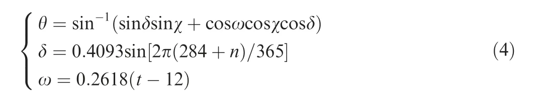
wheretrepresents the day time in hours which varies from sunrise till sunset:

2.3.Electrical power conversion model
When the solar aircraft morphs into a planar wing,the output power of PV array can be calculated with

whereScis the area of the thin film PV array mounted on the wing surface and ηinis an aggregate energy transfer efficiency from sunlight to battery(ηin=ηenηscηmtηbc).The efficiencies of the systems are listed in Table 2.
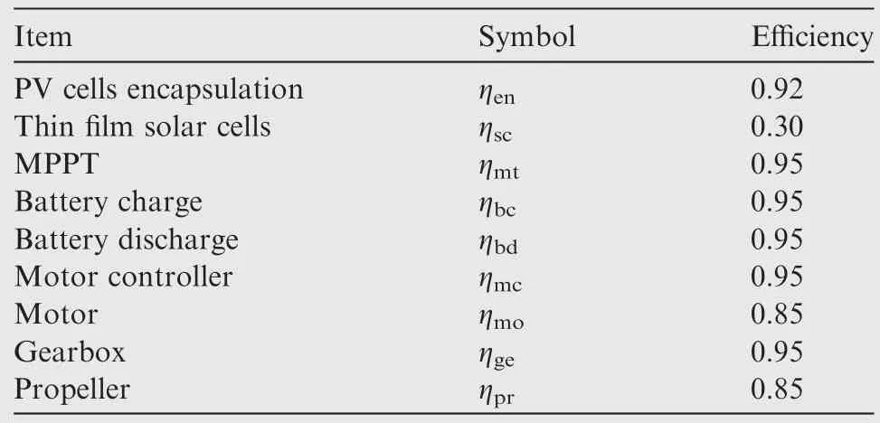
Table 2 Energy transfer system efficiencies.
To calculate the PV array output power of the Λ-shaped wing,the solar incidence angle should be formulated as a mathematical model of flight attitude and sun position.As shown in Fig.2,the Earth coordinate axisOX,OYandOZare expressed positive in the directions of north,west anddown.Theoxaxis of the aircraft frame is expressed out the nose,ozis in the plane of symmetry and perpendicular toox,andoyis expressed out the right wing.As the small pitching angle is negligible,the solar incidence angle can be derived as35

whereiis the solar incidence angle,ψ is the yawing angle,ω is the solar azimuth angle,and φ is the morphing angle.
As shown in Fig.2,the wing-morphing angles are φ and-φ for the Λ-shaped wing pointing toward the sun and backward the sun,respectively.In this condition,the corresponding solar incidence anglesi’andi’’are given by

Fig.2 Aircraft body-fixed frame o (x,y,z) and Earth-fixed coordinate frame O (X,Y,Z).

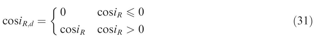
For the varying wing-morphing angle and solar elevation angle,the additional power output from PV array of the Λshaped wing flight than the planar wing flight can be derived as follows.
(1) Fig.3(a) shows that half of the PV array is exposed to the sun because the solar elevation is smaller than the morphing angle.The additional output power of the Λ-shaped wing than the planar wing can be calculated with

It can be seen from Eq.(9)that,when the yawing angle and the solar azimuth angle satisfy ψ-ω=0.5π,the Λ-shaped wing can achieve more additional output power than the other yawing angles:

Because of the symmetrically Λ-shaped wing-morphing configuration,there are two optimal yawing angles with respect to a single solar azimuth angle as given by

(2) For the solar elevation larger than the wing-morphing angle in Fig.3(b),the PV array is totally exposed to the sun and the additional output power of the Λshaped wing than the planar wing is
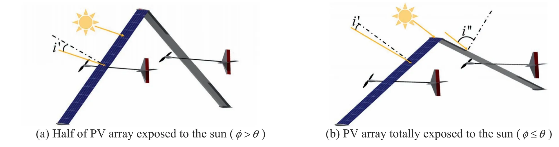
Fig.3 The Λ-shaped wing-morphing solar aircraft exposed to the sunlight under two flight conditions.

By substituting Eq.(8) in Eq.(12),the additional output power model is represented by

It can be seen from Eq.(13) that,when the solar elevation angle and the wing-morphing angle satisfy φ ≤θ,the Λshaped wing is incapable of achieving more solar power harvesting than the planar wing.Therefore,Eq.(10) is selected to establish the net power input model in the next section.In addition,as expressed in Eq.(11),the optimal flight attitude of the Λ-shaped sun-tracking solar aircraft is dynamically changing its yawing angle with respect to the solar azimuth angle to make the horizontal projection of sunlight perpendicular to the fuselage axis.
2.4.Power consumption and flight speed models
To obtain the optimal wing-morphing angle and flight trajectory that can maximize PV array output power,the power consumption and the flight speed of the example Λ-shaped solar aircraft should be formulated with functions of the wingmorphing angle.The power required from battery for sustaining flight can be calculated with

where ρ is the air density at 20 km,gis the acceleration of gravity,ηoutis the energy transfer efficiency from the battery to the thrust of the propeller (ηout=ηbdηmcηmoηgeηpr),CdandClare the drag and lift coefficient,respectively.
In steady level flight,the lift of the aircraft is equal to its weight (mg=0.5ρv2SCl) and the flight speed is given by
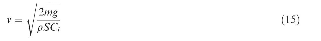
Based on Eqs.(14)and(15),the electrical power consumption model and the flight speed model of the example solar aircraft can be formulated with functions of the Λ-shaped wingmorphing angle
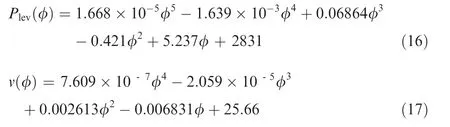
where φ is the Λ-shaped wing-morphing angle in degrees.
Compared with the planar wing,the extra power consumption of the Λ-shaped wing can be obtained with

wherePplanaris 2831 W which is the power required from battery for the planar wing flight.
3.Trajectory optimization method under constrained flight region
In researches,31,36the sun-tracking solar aircrafts were designed to travel along a large arc flight path to track the sun position and the aircrafts were incapable of maintaining its position over an area of interest for persistent surveillance missions.To solve this problem,this section focuses on developing a trajectory optimization method for planning the flight path of sun-tracking solar aircraft under the constraint of a given mission region.
3.1.Round-trip sun-tracking flight theory
As shown in Fig.4,the Λ-shaped sun-tracking solar aircraft is designed to operate within a circular region.The flight position of the aircraft is constrained within a radius constraint ofRfrom the Start Position (ST PO).To operate the sun-tracking aircraft within the given flight region,the aircraft needs to change its heading into an opposite direction by level turning flight nearby the boundary.As the turn rate can be positive and negative,the aircraft can reverse its course nearby the boundary through left-turning and right-turning flight as shown in Fig.4(a) and (b),respectively.The time Δtit takes for the solar aircraft making a 180° turn can be obtained with

and the bank angle β during the turning flight is

where ϖ is turn rate of the aircraft.As the stratospheric solar aircraft is designed to change its flight direction with a small turn rate and low flight speed,the bank angle caused by the turning flight is small and neglected in this study.
The level-turning flight nearby the boundary will cause less power output from PV array because that the yawing angle and the solar azimuth angle can not satisfy Eq.(11).The optimal flight strategy is to determine the optimal time to start a 180° turn so that the turning arc is tangent to the boundary.For a given flight region,this strategy can minimize the frequency of level-turning operations and maximize the time spent with the optimal yawing angle.
To optimize the flight path within a given flight region,the optimal yawing angle,flight speed and position of the large arc sun-tracking flight should be optimized and taken as the initial inputs.Letrtbe the radial distance between the sun-tracking aircraft and ST PO.We can check the time-varying radial distancertto obtain the timetjwhen the aircraft reaches the region boundary.As shown in Fig.4,there exists the optimal timewhen the aircraft begins to make a 180°turn and the turning arc is tangent to the boundary.Due to the symmetric Λ-shaped morphing-wing,the aircraft still remains the optimal yawing angle and the optimal wing-morphing angle after making a 180° turn.Therefore,the method proposed enables the Λ-shaped sun-tracking aircraft to maintain its optimal yawing angle and morphing angle most of time during daylight flight.
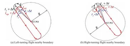
Fig.4 Left-turning and right-turning flights nearby the region boundary for changing into reverse direction.
3.2.Trajectory optimization method under constrained flight region
Based on the analysis of Section 3.1,the trajectory optimization process for operating the sun-tracking aircraft under a given radius constraint can be described as follows:(A) The large arc sun-tracking parameters are optimized and taken as initial inputs.(B) For a given radius constraint,search for the optimal time to make a 180° turn so that the turning arc is tangent to the region boundary.(C) Update the optimal flight trajectory to find the next optimal time for levelturning operation.(D) The optimization process is executed repeatedly until the aircraft is totally constrained within the flight region.The details of the proposed optimization method are presented as below.
3.2.1.Initial optimization for theΛ-shaped solar aircraft under large-arc sun-tracking flight
As both power consumption and PV array output power are related to the Λ-shaped wing-morphing angle,the net power model is put forward by subtracting Eq.(18) from Eq.(10):

Eq.(21) suggests that the net power input is related to the day numbern,PV efficiency ηsc,latitude χ,day timetand wing-morphing angle φ.For a given flight condition,these terms (n,ηsc,χ) are constant and the optimal yawing angle can be obtained using Eq.(11).The optimization objective is to find the optimal wing-morphing angle φoptthat can maximize net power input,which can be expressed as

With the optimized wing-morphing angle,the optimal flight speedvoptcan be obtained with Eq.(17).Using the optimal flight speed and yawing angle,the optimal trajectory of large arc sun-tracking flight can be computed with
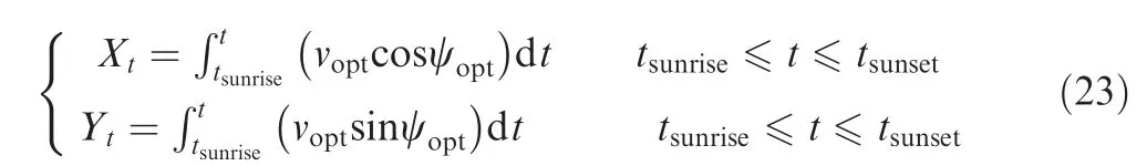
and the radial distance between the sun-tracking solar aircraft and ST PO is obtained with

It should be noted that the optimal morphing angle and maximum net power input to battery under large-arc suntracking flight is obtained with the ‘‘max”and ‘‘index”functions of MATLAB in the research31where the effectiveness and feasibility of the optimization method was validated using the NLPQL solver.The optimization algorithm of the suntracking solar aircraft under the large arc sun-tracking flight is presented in Algorithm 1.
Algorithm 1:Pseudo-code of optimal flight trajectory under large arc sun-tracking flight.

3.2.2.Flight trajectory optimization under station-keeping radius constraint
Step 1.For a given time step dt,the timetfrom sunrise to sunset is a vector withNcomponents.The flight position and radial distance from ST PO are alsoN-dimensional vectors.Define the variation of yawing angle for making a 180-turn operation to be a vector withntcomponents:

wherent=Δt/dt+1 represents the number of steps for the aircraft changing into a reverse flight direction.For the given optimal large arc flight trajectory,we can find the minimumjwhen the aircraft attjreaches the boundary of the given radius constraint,i.e.,rj≥R,j=1,2,...,N.
Step 2.As the optimal time that the aircraft starts to make a 180° turn satisfiesthe temp time for starting turning is set toThe temp yawing angle and flight speed fromt1toare assigned with

Step 3.Judge if the temp maximum radial distance satisfiesIf it is,the temp time when the aircraft begins to make a 180° turn is earlier than the expected optimal time,and the starting time of turning operation is assigned withThen the temp yawing angle,flight location and maximum radial distance is recalculated by executing Step 2.If the aircraft during the turning operation reaches the region boundary(i.e.,),the iteration is stopped and the optimal timetkis obtained to execute Step 4.
Step 4.With the optimal time for starting level-turning operation,the optimal yawing angle fromtktotNare updated using Eq.(28).With the updated yawing angle,the optimal flight trajectory and radial distance of the sun-tracking aircraft are recomputed using Eqs.(23)and(24),respectively.It can be believed that the updated flight location fort∊[t1,tk] are unchanged,while the flight location aftertkvaries.

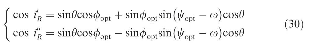
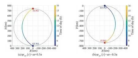
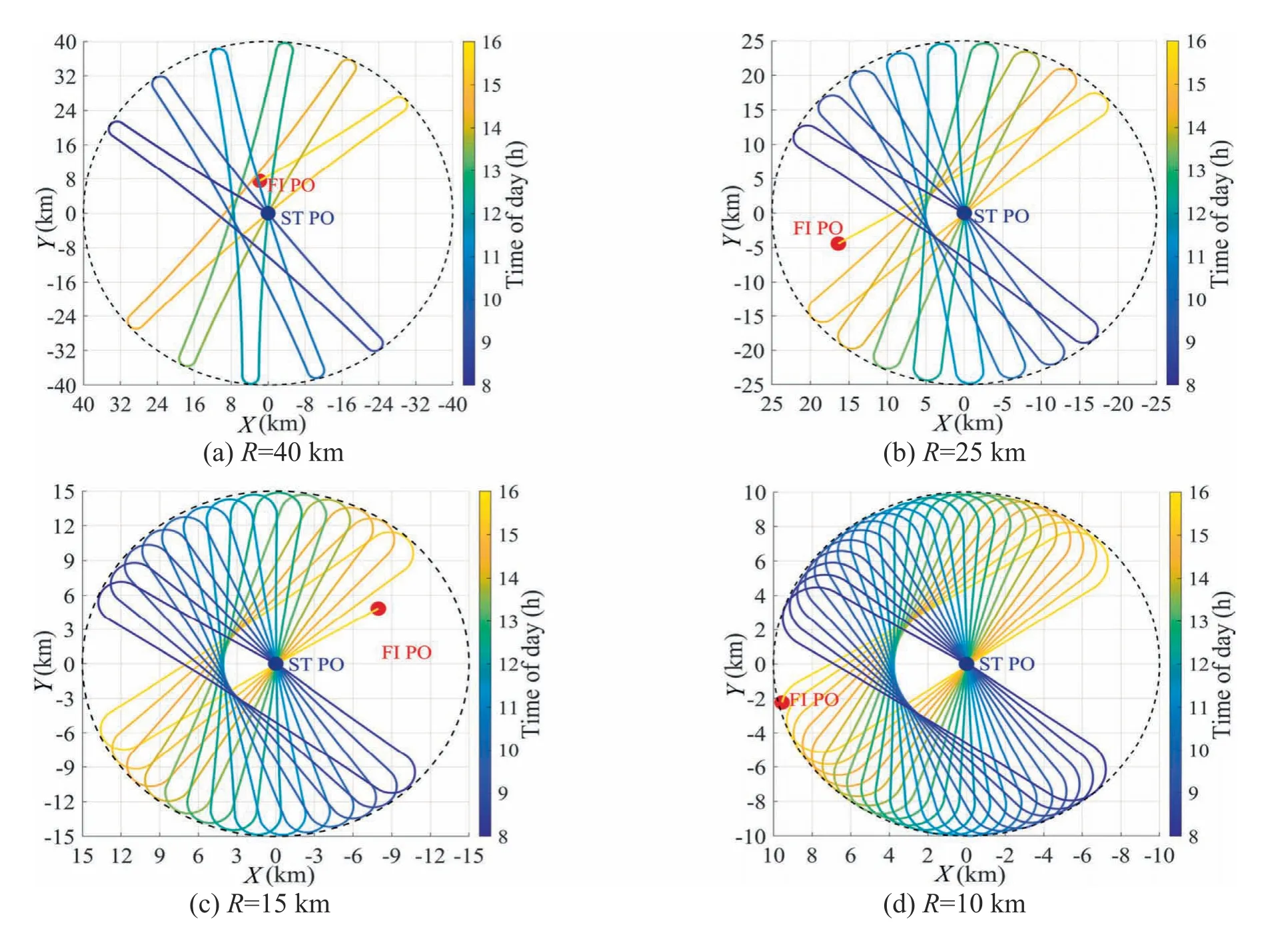
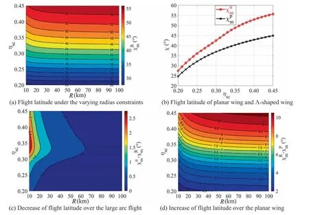
Step 5.As the updated radial distance forsatisfiesrt The flow chart of the optimization procedure is shown in Fig.5 and the pseudo-code of the optimization algorithms for the sun-tracking solar aircraft under station-keeping radius constraint is presented in Algorithm 2.It should be noted that the flight trajectory after sunset is not optimized in this study,because the solar aircraft will morph into a planar wing and the flight direction is unrestricted. Fig.5 Flow chart of trajectory optimization method for a circular region with a radius constraint of R. Algorithm 2:Pseudo-code of trajectory optimization under station-keeping radius constraint. As the updated yawing angle ψopt(t)during the period of level turning operation can not satisfy Eq.(11),the net power input model of Eq.(21) is not available which should be modified.Using Eq.(8),the solar incidence angles of the left wing and right wing under the radius constraint ofRcan be expressed with Note that the cosine values of solar incidence angle can not be added directly to calculate the net power input,because the cosine values may be negative during the turning operations nearby the boundary.It should be defined that if the cosine term of the solar incidence angle is negative,it is set to zero: With the definition of Eq.(31),the net power input model under the radius constraint ofRcan be expressed as To evaluate the potential of day-night cycle perpetual flight,the energy balance model is proposed with the total energy output from PV array subtracting the total energy consumption: wherePpayloadandPavionicare assumed to be 200 W and 300 W for the payload and the avionic system,respectively. With the optimal sun-tracking approach developed in Sections 2 and 3,simulations on the optimal flight trajectory and controls of the example Λ-shaped sun-tracking solar aircraft are performed to verify the effectiveness of the proposed method.As the radius constraint will affect the frequency that the suntracking solar aircraft makes a 180° turn and also the time spent with the optimal yawing angle,the effects of varying the radius constraint on optimal flight trajectory,energy performance and maximum perpetual flight latitude are explored numerically. For a given flight latitude of 50°N,PV efficiency of 0.3 and flight date of winter solstice,the optimum yawing angle and wing-morphing angle of the example Λ-shaped sun-tracking solar aircraft can be optimized with Eq.(11) and Eq.(22),respectively.With the optimized morphing angle,the flight speed required of the Λ-shaped aircraft is obtained using Eq. (17).Based on the yawing angle and flight speed optimized,the large arc sun-tracking flight trajectory can be obtained with Eq.(23).For the symmetric Λ-shaped sun-tracking aircraft,there exist two optimal yawing angles with respect to a single solar azimuth angle as expressed in Eq.(11).Thus,there are two optimal sun-tracking flight trajectories for the given flight condition.Fig.6(a) and (b) represent a north-west and southeast large arc sun-tracking flight path at sunrise time,respectively.The symmetric Λ-shaped sun-tracking aircraft can achieve the maximum net energy input to batteries by means of both optimal flight path. In this paper,the optimal north-west flight trajectory in Fig.6(a) is selected as initial input for the optimization under a given station-keeping radius constraint.With the optimal large-arc sun-tracking flight path,the radial distance away from ST PO can be obtained with Eq.(24).The optimized yawing angle,flight speed and trajectory of the large arc suntracking flight are taken as initial inputs.Then,for a given radius constraint of 50 km,the optimal flight path of the sun-tracking aircraft can be optimized using Eqs.(26)-(29),as shown in Fig.7.It should be noted that the dot of FI PO represents the final finish position of the optimized flight trajectory,and the daytime corresponding to the trajectory is distinguished with colors.In the trajectory optimization process,the time step is set to 3.6 s,and the turn rate used to reverse the aircraft flight direction is set to 1(°)/s. Fig.6 Optimized flight trajectories of unconstrained large-arc sun-tracking flight for winter solstice. Figs.7(a)and(b)represent the left-turning flight and rightturning flight to change the aircraft’s heading into an opposite direction nearby the boundary of the circular region,respectively.As shown in Fig.7,the optimal flight control approach developed can effectively constrain the flight trajectory of the Λ-shaped sun-tracking solar aircraft within the circular region.It can be observed that the turning arcs are tangent to the boundary of the circular region,implying that the optimization method is effective to minimize the frequency of level turning operations and maximize the time spent with the optimal yawing angle.The optimum flight control and net power input corresponding to the optimized flight trajectory of Fig.7(a) are simulated and shown in Fig.8. Fig.7 Optimized flight trajectories under the station-keeping radius constraint of 50 km for winter solstice. Figs.8(a) and (b) show that the optimal wing-morphing angle varies slightly from 42° to 45° and the corresponding flight speed changes from 30.4 m/s to 31.8 m/s.It can be found that the flight speed presents the same trend as the optimal wing-morphing angle because that the large morphing angle requires high flight speed to maintain steady level flight.As shown in Fig.8(c),to constrain the distance away from the ST PO within the radius constraint of 50 km,the aircraft changes its yawing angle dynamically by making 180° turns nearby the boundary of the circular region.These optimum flight controls can enhance the solar aircraft to achieve more than 3000 W net power input for most of the time during the daylight flight,as depicted in Fig.8(d).But for the turning flight nearby the boundary of the circular flight region,the net power input is negative.The main reason is that the yawing angle and the solar azimuth angle can not satisfy Eq.(11)during the period of level turning operations,which causes less power output from PV array than that of the optimum suntracking flight direction.It should be noted that,for the suntracking solar aircraft with an asymmetric wing-morphing configuration,the aircraft need to dynamically morph its optimal wing-dihedral angle from φ to–φ during the level turning operation nearby the region boundary. Fig.8 Optimal flight controls and net electrical power input under the radius constraints of 50 km for winter solstice. To evaluate the energy performance within the station-keeping radius of 50 km,the battery input power and the electrical energy stored in battery are simulated as shown in Figs.9(a)and (b),respectively.For comparison,the energy performances of the example solar aircraft with the large arc suntracking flight and the planar wing flight are also presented in the figure.Note that the negative values in Fig.9(a)implies that the solar aircraft requires extra electrical power output from the battery for sustaining flight.Fig.9(a) shows that the optimal flight path planning method enables the aircraft to achieve same battery input power as the large arc suntracking flight most of time,except when the aircraft makes 180° turns.During the daylight flight close to the dawn and dusk,the power output from the PV array of the optimal Λshaped wing flight is sufficient for sustaining flight,whereas the planar wing flight requires extra power output from the battery because of the low solar elevation angles. As shown in Fig.9(b),the electrical energy stored in battery at the sunset time is 42.16 kW h for the large arc flight,40.88 kW h for the radius constraint of 50 km,and 15.91 kW h for the planar wing.Compared with the planar wing,the increments of the electrical energy input are 26.25 kW h and 24.97 kW h for the large arc flight and the mission radius of 50 km,respectively.Because of the turning flight nearby the region boundary,the decrease of the output energy from PV array is 1.28 kWh which only accounts for 4.8% of the total net energy.Therefore,for the given circular region with the radius constraint of 50 km,the optimal flight control approach enables the Λ-shaped solar aircraft to achieve almost the same battery input energy as the large arc sun-tracking flight while constraining the flight path of the sun-tracking aircraft within the circular flight region by turning flight nearby the boundary. Fig.9 Comparison of energy performance for the example solar aircraft with Λ-shaped wing and planar wing. For the varying radius constraints from 10 km to 40 km,the optimal sun-tracking flight path are simulated as shown in Fig.10.The results indicate that the aircraft can be constrained within the circular regions and the smaller radii cause the aircraft to achieve more passes nearby ST PO as expected.The maximum distance away from the ST PO can be set as required.In addition,the turning arcs are tangent to the boundaries for the varying station-keeping radius constraints,implying that the frequency of turning operations is minimized and the power output from PV array is maximized.Although the optimum yawing angle of the Λ-shaped sun-tracking aircraft dynamically varies with the solar azimuth angle,the round-trip flight path planning method can compensate for the deficiency and the sun-tracking solar aircraft can be used to monitor the target area on the ground as mission radius required. Fig.10 Time-varying optimized flight path under varying radius constraints at 50°N for winter solstice. Considering that the frequency of level-turning operations is tightly related to the radius constraint of a given mission region,the effect of the varying mission radii on net energy and energy balance are investigated numerically.For the varying radiiR∊[10,100] km,latitudes χ ∊[0°,66°] and PV efficienciesthe net power input on winter solstice can be obtained using Eqs.(30)-(32).By integrating the net power from sunrise to sunset,the net electrical energyunder the varying radius constraints is obtained as shown in Fig.11(a).For day-night cycle operation,the energy stored in batterycan be calculated using Eq.(33),as shown in Fig.11 (b). The contour maps in Fig.11(a) demonstrate that the net input energy loss caused by the turning operation is small and negligible,especially for the radius constraints larger than 30 km.Due to slightly change of net energy,the energy balance in Fig.11(b) remains nearly constant as the radius constraint varies.It can be inferred that the optimal flight path planning method enables the sun-tracking aircraft to achieve almost the same advantage in energy performance as the large arc flight.In addition,there exists more net energy between the 45°N and 60°N latitudes than the other latitudes.The significant net energy can improve the perpetual flight latitude because most solar aircrafts can not achieve continuous flight in these regions for the less daytime and lower solar elevation angles.37 With the electrical energy residual in battery of Fig.11(b),the contour map of the theoretical maximum perpetual operating latitudeunder the varying radius constraints can be obtained as shown in Fig.12 (a).The maximum perpetual flight latitude of the large-arc sun-tracking flightand the planar wing flightcan be optimized as shown in Fig.12(b).For a given station-keeping radius constraint,the maximum perpetual operating latitude is a two-dimensional plotand the decrease of flight latitude over the large-arc sun-tracking flight can be calculated with the flight latitude of large arc flight subtracting the flight latitude of the station-keeping constraintFor the varying station-keeping radius constraints,the decrease of the maximum operating latitude can be obtained as presented in Fig.12(c),which is a three-dimensional array.Using the same method,the increase of operating latitude under the radius constraint over the planar wing is obtained as shown in Fig.12(d). Fig.11 Effect of varying radius constraints on net energy and energy balance for winter solstice. Fig.12 Comparison of maximum perpetual operating latitude under the varying radius constraints on winter solstice. It can be observed from Fig.12(a) that,when the radius constraint is larger than 30 km,the maximum perpetual operating latitude remains nearly constant as the radius constraint varies.Compared with the large arc sun-tracking flight,the decrease of the maximum perpetual operating latitude is less than 1° for the radius constraint larger than 30 km,as shown in Fig.12(c).The proposed method enables the Λ-shaped sun-tracking solar aircraft to achieve remarkable increase of the maximum operating latitude than the planar wing as shown in Fig.12(d).Therefore,the trajectory optimization method developed for operating the sun-tracking aircraft under the mission radius constraint enables the aircraft to achieve perpetual flight at almost the same latitude as the large arc sun-tracking flight. This paper presents an optimal flight control approach for planning the flight path of sun-tracking solar aircraft under the constraint of a given mission region while maximizing the battery input power.With the trajectory optimization models established,the optimal flight trajectory and controls of a stratospheric Λ-shaped sun-tracking solar aircraft for a circular region that constrained with a station-keeping radius of 50 km are optimized.Then,to validate the effectiveness and availability of the proposed method,the effects of varying the mission radius on optimal flight trajectory,energy performance and maximum perpetual flight latitude are explored quantitatively. Based on the results and analysis of this study,the main conclusions can be drawn as follows. (1) The proposed optimal flight control method is effective to plan the flight path of the example Λ-shaped suntracking solar aircraft within the mission region by turning flight nearby the boundary of radius constraint.The optimization algorism ensures the turning arcs to be tangent to the boundary of the mission region,which can minimize the frequency of turning operations and maximize the time spent with the optimum yawing angle. (2) During daylight flight,the sun-tracking solar aircraft can achieve the maximum net power input most of the time,except for the flight nearby the region boundary where the aircraft reverses its direction by turning flight.But the energy loss caused by the turning flight is negligible owing to the minimized frequency of level turning operations,which enables the aircraft to achieve almost the same battery energy input as the large arc flight. (3) For the varying radius constraints from 10 km to 40 km,numerical simulations have proved the feasibility and effectiveness of the proposed method on optimizing the flight path under the given mission regions.The net energy input and energy balance remain nearly constant as the radius constraint varies,which ensures the example sun-tracking solar aircraft to achieve perpetual flight at almost the same latitude as the large arc flight. The trajectory optimization method presented in this study can be used to maintain the position of sun-tracking solar aircraft over areas of interest while maximizing the battery input energy.This paper can provide reference to other sun-tracking solar aircrafts for surveillance and monitoring missions under station-keeping constraints. Declaration of competing interest The authors declare that they have no known competing financial interests or personal relationships that could have appeared to influence the work reported in this paper. Acknowledgements The authors gratefully acknowledge the support of the National Natural Science Foundation of China (Nos.11902156 and 11672133).This work is also supported by the Fundamental Research Funds for the Central Universities,China (No.309201A8802).


3.3.Energy and power models under constrained flight region


4.Results and discussion
4.1.Optimal flight trajectory under the radius constraint of 50 km


4.2.Power and energy performance under the radius constraint of 50 km

4.3.Effect of radius constraint on optimal flight trajectory
4.4.Net energy and energy balance under the varying radius constraint
4.5.Effect of radius constraint on maximum perpetual flight latitude

5.Conclusions
杂志排行
CHINESE JOURNAL OF AERONAUTICS的其它文章
- Parameter effects on high-speed UAV ground directional stability using bifurcation analysis
- Supersonic flutter control and optimization of metamaterial plate
- Review of in-space assembly technologies
- Utilisation of turboelectric distribution propulsion in commercial aviation:A review on NASA’s TeDP concept
- The influence of inlet swirl intensity and hot-streak on aerodynamics and thermal characteristics of a high pressure turbine vane
- Full blended blade and endwall design of a compressor cascade