Experimental research of active vibration and noise control of electrically controlled rotor
2021-10-25JinchoMAYngLUToyongSUShujunGUAN
Jincho MA ,Yng LU,* ,Toyong SU ,Shujun GUAN
a National Key Laboratory of Rotorcraft Aeromechanics,Nanjing University of Aeronautics and Astronautics,Nanjing 210016,China
b School of General Aviation,Nanchang Hangkong University,Nanchang 330063,China
KEYWORDS Active control;Experiment;Flaps;Noise;Rotor;Vibration
Abstract Electrically Controlled Rotor (ECR),also called as swashplateless rotor,applies blade pitch inputs via trailing-edge flaps system instead of traditional swashplate mechanism.In addition to primary control,rotor vibration reduction and noise alleviation are also achievable via applying higher harmonic control inputs with the trailing-edge flaps.In this paper,the feasibility of ECR to reduce vibration and noise actively is verified experimentally.Firstly,the test scheme of ECR active vibration and noise control is proposed,and the ECR test platform is modified according to the test scheme.Then,an adaptive control algorithm based on Kalman filter is developed.Lastly,hover and wind tunnel tests is performed to verify the feasibility of ECR active vibration and noise control.The results demonstrate that the ECR are effective for reducing rotor vibration and noise simultaneously.In the hover condition,the ECR can reduce the in-plane hub vibration by 42%and the inplane noise by 4 dB.In wind tunnel condition,ECR can reduce the hub vibration by 75%and the BVI noise by 3 dB.
1.Introduction
Electrically Controlled Rotor (ECR) is a kind of swashplateless rotor system,which applies blade pitch inputs through trailing-edge flaps system driven by embedded electric actuators.Compared with the traditional swashplate rotor system,ECR has the advantages of simpler structure,lighter weight,and smaller parasite drag,etc.In fact,without the constrain of the swashplate,the trailing edge flaps of ECR can provide not only primary control,but also higher harmonic control inputs,which can provide active vibration and noise control function similar to Active Controlled Flap (ACF) system.So far,theoretical and experimental researches on the use of ECR for helicopter primary control have been carried out quite a lot,while researches related with ECR active vibration and noise control are still limited.
NASA first proposed the concept of ECR in 2000.1Since 2002,Shen and Chopra carried out a series of numerical studies on the driving power requirements of trailing edge flaps for ECR primary control,2and the influence of the ECR design parameters for primary control efficiency and rotor performance.3,4while for experiment,ECR still need to solve the problem of actuators.ECR primary control requires low frequency large amplitude actuators,while the active noise and vibration control requires high frequency small amplitude actuators,it is very difficult to design an actuating system to meet these two requirements simultaneously.In 2007,Uwe developed a kind of swashplateless rotor system driven by Electromechanical Actuators (EMA) integrated inside the hub.5In 2010,Lorber et al.developed a full-scale ECR based on brushless motors and tested the ECR in hover and wind tunnel conditions.6In 2010 Woods et al.designed a swashplateless rotor system actuated by Pneumatic Artificial Muscle(PAM)and tested it in vacuum chamber whirl test rig.7In 2015 Wang et al.developed a ECR system using the Limited Angle Direct-Drive Motor(LADDM),a multi-body dynamics model is used to determine the blade pitch moment of the LADDM.8,9The test demonstrated the feasibility of LADDM to provide ECR blade pitch control,10In 2017,Saxena and Chopra developed a set of model ECR based on brushless motors and conducted hovering tests.11All the above researches have verified the feasibility of ECR primary control,but they didn’t demonstrate the feasibility of ECR for simultaneous primary control and active vibration and noise control.
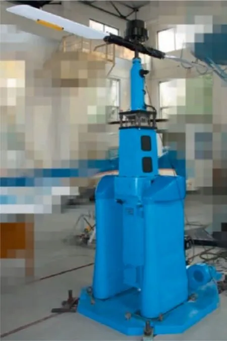
Fig.1 Overview of ECR test platform.
For the researches about ECR active vibration and noise control,Shen explored the feasibility of UH-60 ECR for both helicopter primary control and active vibration control by simulation in 2006.The flap inputs for active vibration control was obtained using the T-matrix algorithm and superimposed with the primary control inputs.The Results showed that the ECR can reduce the vertical vibration load and longitudinal hub bending moment load over 90%,and the in-plane vibration load about 40% at the Blade Pass Frequency (BPF).12So far,there were only simulation studies,but no further literature related with experimental studies on ECR active vibration or noise control could be found.
Authors designed,fabricated and tested a model ECR platform in 2004,but subjected to the performance of the actuators,this model ECR platform only verified the feasibility of ECR primary control.13Since then the steady control response of ECR14and the mechanisms of ECR for rotor performance enhancement,15vibration and noise reduction16,17were studied by simulation respectively.In 2017,we developed a set of 3-meter scale model ECR test platform with improved actuating system and carried out experimental studies on ECR primary control.18In fact,the model ECR platform could also be used to conduct active vibration and noise control tests after corresponding modifications.
In order to verify the feasibility of ECR simultaneous active vibration and noise control,the existing model ECR platform is modified through installing corresponding measurement and control equipment.And the ECR active vibration and noise control tests are conducted in both hover and wind tunnel conditions.
The main contents of this paper are arranged as follows:in the second chapter,the test scheme based on the model ECR is introduced.In the third chapter,the preparation of the vibration and noise measurement and control equipment is explained.In the fourth chapter,the tests results obtained in hover and wind tunnel are described and analyzed in detail.
2.Model ECR platform and test scheme
2.1.Model ECR platform
The model ECR test platform is shown in Figs.1 and 2 gives its schematic diagram:the ECR platform is consisted of three parts:the main rotor,the test rig and the measurement and control system.The model ECR’s main rotor is consisted of the hub,the blades,the trailing edge flaps and the actuators.Parameters of the model ECR are given in Table 1.And the geometric shape and the main dimensions of the blade are illustrated in Fig.3.The test rig is consisted of the support base,the side strut and the main rig body.The ECR is driven by a 7.5 kW DC motor located in the main rig body,which could be tilted at the range of±15° to provide the deflection of the ECR rotor shaft.For the ECR measurement and control system,two Hall-effect angle sensors are installed on both sides of each flap to measure the deflection angle of flap.And the signals of the flap deflection angle,blade pitch angle,control inputs of actuators and the driving power of actuators are transmitted through the slip ring on the rotor shaft.A servomotor and a photoelectric encoder are installed in the side struts to provide desired rig body tilt angle.The rotary speed and azimuth signals of the ECR are measured by the rotor shaft photoelectric encoder,which are used as the reference for triggering sampling,calculation,output and system online identification of the control algorithm.The power cabinet mainly provides electric power for the test platform.And the electronic cabinet is mainly used for data acquisition,important parameters monitoring and control command sending.
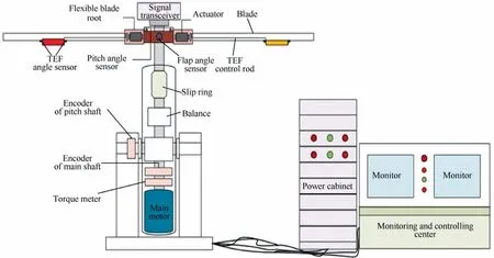
Fig.2 Schematic diagram of model ECR system.
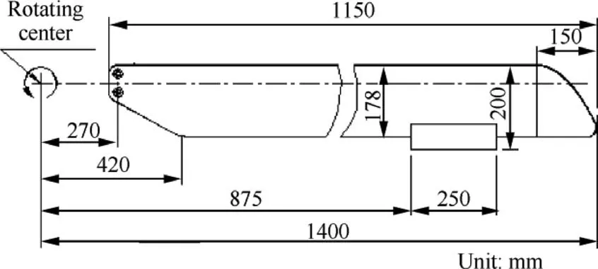
Fig.3 Geometric of model ECR blade.
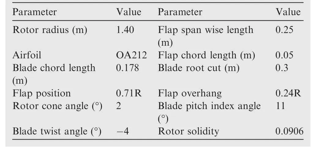
Table 1 Main parameters of model ECR.
2.2.Test scheme
The vibration and noise characteristics of the model ECR are related with the test status.Therefore,it is necessary to make test plans for different test conditions.
The rotor vibration load mainly comes from the cyclic aerodynamic force on the rotor disk.Because of the filter effect of the rotor hub,only the BPF hub load can be transmitted to the fuselage.The model ECR is equipped with a two-blade rotor,therefore,the 2/rev (1st BPF) hub longitudinal,vertical and lateral accretionsFx,FyandFzare selected as the vibration control objects.
The rotor noise is usually composed of discrete frequency noise and wide-band noise.The discrete frequency noise can be divided into the thickness noise and the loading noise.When in hover,blade thickness noise plays a dominant role.Its directivity distribution is mainly concentrated at about±30° around the rotor rotating plane,and its frequency mainly focused on 1st-3rd BPF.Therefore,the 1st-3rd BPF Sound Pressure Level(SPL)of the model ECR thickness noise is taken as the active noise control object in hover.
However,in some specific work conditions,such as lowspeed descent,the Blade Vortex Interaction (BVI) phenomenon will occur.At this moment,the loading noise increases significantly and becomes the dominant component of rotor noise.Its directivity is mainly concentrated beneath the rotor rotation plane,and the frequency range is 6th–40th BPF.Therefore,for the BVI state,the 6th-40th BPF SPL of the model ECR loading noise is taken as the active noise control objects.
Considering the above analysis,the tests are carried out including two stages:hover and wind tunnel (to simulate BVI phenomenon)conditions.Table 2 shows the specific test states,control inputs and object settings.First,the measurement and control system is adjusted according to the test conditions:for hovering state,the microphone for feedback signal collocation is installed in the rotating plane,and the control object is adjusted for only vibration control,only noise control and simultaneous vibration and noise control respectively.For wind tunnel condition,the microphone for feedback signal collocation is installed beneath the rotating plane.To simulate the BVI phenomenon,the wind speed and the rotor shaft angle are first adjusted continuously until the measured feedback noise level in medium and low frequency increases significantly.Then this condition is taken as test condition,and ECR active control is conducted for only vibration control,only noise control and simultaneous vibration and noise control respectively to verify the active control effect of the model ECR on the vibration and noise level,and study the influence of the control parameters.

Table 2 Test states and control parameters.
3.Test preparation
The ECR test platform is built for ECR primary control testing.In order to carry out the ECR active vibration and noise control test,the platform is modified according to the testscheme.A vibration and noise measurement system is added to acquire the vibration load and the near-field noise of the model ECR.An active vibration and noise control algorithm is developed,and the corresponding frequency-domain adaptive control software is compiled.
3.1.Vibration and noise measurement and control system
Fig.4 illustrates the working principle of the ECR active vibration and noise measure and control system.The system consists of three parts:the driving system,the control system and the measurement system.The driving system is inherited from the former ECR test platform,and the measurement system is used to obtain the rotor vibration signal,noise signal and main rotor azimuth signal.Vibration and noise signals are filtered and amplified by the CM3508 dynamic signal conditioner and the main rotor azimuth signal is measured by the absolute encoder.After that,the measured signals are sent to the control system for further processing.In the control system,the conditioned vibration and noise signals and rotor azimuth signals are sent to PCI-9111 data acquisition card for collection and storage.These signals are also sent to the SEED-DSP2812m embedded DSP controller,and the required active control output signals are then calculated by adaptive active control algorithm.

Fig.4 Principle of ECR active vibration and noise control system.
The measure system has two different configurations depending on test states.For hover test,two triaxial acceleration sensors are installed to measure the vibration level of the rotor hub.As shown in Fig.5,the No.1 acceleration sensor is located at the upper cover plate of the balance under the hub.During test,it was found that thexdirection(longitudinal)vibration level of the model rotor was higher than theyandzdirection(vertical and lateral)vibration level.Therefore,the 2/rev longitudinal vibration level of No.1 acceleration sensor is taken as the vibration feedback signal of the controller.The vibration level of other directions are acquired as the monitoring signal.No.2 acceleration sensor is installed in the center of the platform under the balance to monitor the vibration level at the non-feedback position of the platform.Three microphones were installed at±30°around the rotor rotating plane to measure the low-frequency in plane noise level of the model rotor.The microphone installation position is shown in Fig.6.The SPL measured by No.2 microphone is taken as the noise feedback signal of the controller,and the rest microphones are taken as monitoring signals for acquisition.

Fig.5 Installation position of triaxial acceleration sensors.

Fig.6 Installation position of microphone for hover test.
For the wind tunnel condition,the hub vibration levels in all three directions are quite serious,so the 2/rev triaxial vibration level in of No.1 acceleration sensor is taken as the vibration feedback signal for the controller.The No.2 acceleration sensor is still used for monitoring.Draw on the experience of Ref.,19the microphone traverse is decided to be installed only in the advancing side of the ECR.Five microphones are used for wind tunnel testing,and the installation positions are illustrated in Fig.7.Four of the five microphones are used to acquire the sound field distribution beneath the advancing side.As shown in Fig.8 the Mic 1–Mic 4 are installed on the acoustic traverse with a gap of 40 cm.During the test,the acoustic traverse is driven by the step motor and lead screw and moves every 40 cm along the air flow direction to monitor the noise in the area beneath the advancing side.Mic 5 is installed beneath the advancing side to provide a feedback signal for active noise control.

Fig.7 Installation position of microphone for wind tunnel test.

Fig.8 Microphone linear array.
3.2.Control algorithm and control software
To obtain optimal vibration and noise control input,a frequency domain adaptive control algorithm based on Kalman filtering method is developed for ECR.Fig.9 illustrated the principle of the algorithm.The hub acceleration signal and the rotor noise signal is transferred into frequency domain by Fast Fourier Transform (FFT).And the obtained 1 BPF longitudinal hub vibration amplitudeand the 1st-3rd or the 10th-12th BPF noise levelSPL2(11)BPF,are selected as feed back signals.The feed back signals serve two purposes,on the one hand they are used to generate the control inputs[δ2c,δ2s,(δ3c),(δ3s),(δ4c),(δ4s)]T;on the other hand the signals are also used for the identification of the transfer matrixT.Finally the active control inputs will be combined with the pilot’s primary control inputs[δ0,δ1c,δ1s]Tand converted to time domain to control the flap actuator.Details about the control algorithm are described as follows:
During the test,the model ECR is manually trimmed by the test personnel,while the higher harmonic control inputs for the active vibration and noise control are calculated by the active control algorithm,and then superimposed to the primary control signal:

Where δ0,δ1c,δ1sare the collective pitch,cyclic pitch amplitudes of the flaps;δactis the active control input of vibration and noise;δpcandδpsare the sine and cosine component of the active vibration and noise control signals ofpth harmonic;ψ is the azimuth of the blade.In this paper,the 2,3,4/rev harmonic control of the flaps are used as the control signals for the model ECR active vibration and noise control.The active control signal can be obtained using a frequency domain Tmatrix adaptive control algorithm.20As shown in Fig.9:when the control is applied,the vibration and noise response at the feedback point of the model ECR can be expressed in the following matrix form:

Fig.9 Schematic diagram of control algorithm.

whereziis the vibration and noise response vector of each harmonic in theith step of the control iteration;Ax,Ay,Azare the triaxial acceleration of the measured point of the platform;SPL is the noise sound pressure level measured by the feedback microphone;and the superscripts BPF represent the harmonic order of noise signals.For the 2 blades model ECR,the vibration signal only uses 2/rev harmonic component,while the noise signal is selected according to different test states:in hover condition,1st-3rd BPF rotor in-plane noise is used as feedback signal;in wind tunnel condition,8th-13th BPF loading noise beneath the rotor advancing side is used as feedback signal.is the non-controlled vibration and noise response vector of each harmonic.uiis the harmonic control vector of flaps.is the estimated transfer matrix between higher harmonic deflection of the flaps and the vibration and noise response.The estimation is realized by using Kalman filter method.
Taking the vibration and noise response of the model ECR in Eq.(4) and the flap deflection angle and its change rate as the control objectives,the weighted quadratic objective function is constructed as follows:
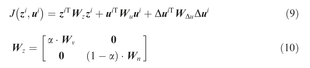
WhereWzis the weight matrix of vibration and noise,WvandWnare the weight matrices of vibration and noise respectively.α is the weight of control object for vibration and noise (0<α<1).By adjusting the α,the vibration or noise control can be achieved.
To minimize the objective function,take the derivative of the objective function with respect to flap control input and make the derivative equal to 0,then the optimal flap control inputs can be expressed as follows:

The algorithm is then integrated to the ECR control software of the upper computer.Its Graphical User Interface(GUI)is shown in Fig.10.Zone ①is used for data acquisition and storage settings.Rotor primary control parameters such as rotor collective pitch,cyclic pitch,and shaft rpm can be set in zone ②.The measured parameters are displayed in zone③on live.zone ④is used for setting higher harmonic active control parameters for active vibration and noise control.And the tilt angle of the test platform can be set in zone ⑤.
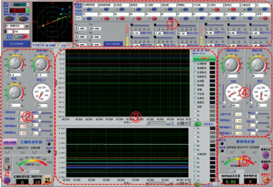
Fig.10 GUI of ECR measurement and control software.
The algorithm introduced above is a frequency domain control algorithm.In the real control process,the controller updates the active control signal every two rotation cycles.In each control signal update cycle,the controller completes the waiting,sampling and calculation functions successively.Fig.11 illustrates the work sequence diagram of the controller.In order to ensure the synchronization of harmonic analysis and control output,the rotor azimuth signal is used as the trigger of each control signal update cycle.In addition,after updating the control output,the response of vibration and noise needs an attenuation period to become stable.Therefore,one rotor rotation is set as the waiting time during the test.In the next rotation,the controller starts data acquisition and updates the control inputs.
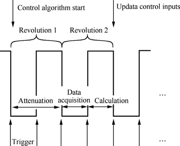
Fig.11 Controller working sequence.
4.Test and result analysis
After modification,the ECR active vibration and noise control tests are carried out in hover and wind tunnel condition respectively.Before experiment a quick onsite calibration is performed to improve the data accuracy,the acceleration sensors are calibrated with gravity,and the microphones are calibrated with acoustic calibrator PCB CAL 200.The ECR is operated in 300 r/min.Both hover and wind tunnel tests include three cases:simultaneous vibration and noise control,only vibration control and only noise control.Every experiment of are repeated at least 3 times.For the statistical results like the bar charts in the following section,data are averaged,and most of the deviation of the measurement data is less than 10%.The weight coefficients of the active control objective function of the vibration and noise of the ECR are set as follows:

4.1.Hover test
As mentioned above,in hover condition,the longitudinal vibration level of the model ECR test platform is more serious than the other two directions,so the 2/rev(i.e.1st BPF)longitudinal acceleration signal of the model ECR test platform is taken as the vibration control object.In addition,the rotor noise is mainly consisted of the thickness noise in hover condition,so the low-frequency noise pressure level in the rotating plane is taken as the noise control object.Tests of simultaneous vibration and noise control,only vibration control and only noise control are carried out respectively.
4.1.1.Simultaneous vibration and noise control
Firstly,according to test state 1 in Table 2,a simultaneous vibration and noise control in hover condition is carried out to verify the active control effect of the model ECR.Take the 2/rev longitudinal vibration level of acceleration sensor 1 and the 1st,2nd and 3rd BPF components noise SPL of microphone 2 as the feedback signals,the 2/rev flaps deflection is taken as control input.Set the weight coefficients as α=0.5 to control the vibration and noise response of the model ECR simultaneously.
Fig.12 illustrates the time history of the 2/rev longitudinal vibration feedback signal of acceleration sensor 1,and the sound pressure feedback signal of microphone 2,and demonstrated the stability of the adaptive control algorithm.The overall control effect is good,the controller is stable and can reduce both noise and vibration significantly in most of the time.While some times the noise signal will overshoot a little bit.It is due to the interference of the background noise.Since the wind tunnel used in present experiment is not an anechoic wind tunnel,the back ground noise is quite serious.But in general,the adaptive control algorithm is functioning well,and the overshoot can be suppressed in time.
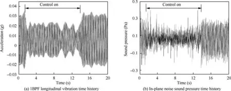
Fig.12 Active vibration and noise control effect during hover test with α=0.5.
Fig.13(a) illustrates the time history of flap deflection in hover test.Active control is applied after 1.5 s.It can be seen that the initial collective pitch angles of two flaps are different.The red flap is 5°,while the yellow flap is about 7°,which is caused by the torsional stiffness difference of the of blades root stainless laminated strips.After the active control is applied,the control algorithm converges quickly.Fig.13(b) illustrates an enlarged time history of the flaps inputs.The flaps 2/rev deflection is a collective control input for the 2 blades ECR,which make the time history of the 2 flaps identical in appearance.

Fig.13 Flaps deflection time history during hover test with α=0.5.
Fig.14 further illustrates the detail variation of vibration and noise level.As shown in Fig.14(a),when active control is applied,the 2/rev longitudinal vibration level is reduced by 54%,the 2/rev vertical vibration level is reduced by 42%,and the 2/rev lateral is reduced by 39%.And in Fig.14(b),the 1st BPF component of in-plane noise is reduced by about 9.4 dB,the 2nd BPF component is reduced by about 6.8 dB,the 3rd BPF component is increased by about 3.8 dB,and the overall in-plane noise is reduced by about 4.1 dB.It shows that for the model ECR,the active control can reduce the vibration and noise simultaneously.
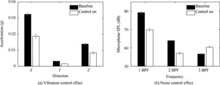
Fig.14 Control effect of simultaneous vibration and noise control during hover test with α=0.5.
4.1.2.Only vibration control
After simultaneous vibration and noise control test,according to the test state 2 in Table 2,a vibration control test is carried out to verify the control effect of ECR for only vibration control in hover state.The same feedback signals as previous test is used,and 2/rev flaps deflection is used as control input.The weight coefficient of the vibration and noise control objectives is adjusted as α=0.999 to make the controller focus on vibration control.
The control result is shown in Fig.15.Focusing on vibration control,the 2/rev longitudinal vibration level of the test platform can be reduced by 75%,while the non-controlled 2/rev vertical and lateral vibration level are also be reduced by 44%and 45%,respectively.It shows that better vibration control effect can be achieved by using only vibration control.However,it can also be seen from Fig.15(b) that focusing on vibration control will lead to an increase in the low frequency in-plane noise of the ECR.The SPL at microphone 1 is increased by 1.4 dB,SPL at microphone 2 is increased by 7 dB,and SPL at microphone 3 is increased by 8 dB.

Fig.15 Active vibration and noise control effect during hover test with α=0.999.
4.1.3.Only noise control
According to the test state 3 in Table 2,a noise control test is also carried out to verify the control effect of ECR for only noise control in hover state.The same feedback signals as mentioned above are used.The weight coefficient of the vibration and noise control objectives is adjusted as α=0.001 to make the controller focus on noise control,and prevent the weight matrix in Eq.(10) from singularity.
The control effect is shown in Fig.16.When focusing on noise control,the 1st BPF component measured by microphone 2 is reduced the most,up to 11.9 dB.The 2nd BPF component is reduced by about 7.7 dB and the 3rd BPF component is increased by about 4.1 dB.The overall in-plane noise reduction is about 5 dB.The 2/rev vibration level in two of the three directions are increased,but the variations are very small.The 2/rev longitudinal vibration level is increased by 7.4%,2/rev vertical vibration level is decreased by 14%,and the 2/rev lateral vibration level is increased by 2.1%.

Fig.16 Active vibration and noise control effect during hover test withα=0.001.
Combining with the results in Section 4.1.2,it can be concluded that,the optimal in-plane noise control will lead to an increasement of in-plane vibration,and vice versa.This is due to the mechanisms of ECR in-plane noise and in-plane vibration control in hover condition.The in-plane noise is mainly caused by the negative thickness noise of the blade.The optimal noise control input can introduce an extra inplane aerodynamic load,which can create a positive loading noise to counteract the original thickness noise.The extra inplane aerodynamic load will also create an extra in-plane hub load.In current experiment state,this extra in-plane hub load doesn’t counteract the original in-plane vibration load.But as shown in Section 4.1.1,the weight object function can allow the control algorithm to find an optimal control input for simultaneous vibration and noise control.
4.2.Wind tunnel test
In order to verify the active vibration and noise control effect of model ECR in the BVI condition,different rotor shaft angles and wind speeds were tested in wind tunnel.It is found that the noise and vibration level increases significantly when the wind speed is 9 m/s and the rotor shaft angle is 14°.Therefore,this condition is used as the test condition in the subsequent tests.
4.2.1.Simultaneous vibration and noise control
Firstly,according to test state 4 in Table 2,simultaneous vibration and noise control in BVI condition is carried out to verify the active control effect of the model ECR.All the 2/rev triaxial vibration level of acceleration sensor 1 are taken as vibration feedback signals,and the 10th,11th and 12th BPF noise SPL of microphone 5 are taken as noise feedback signals,the 2/rev 3/rev and 4/rev flaps deflection are taken as control inputs to achieve better control effect.The object weight coefficient is set as α=0.5to control the vibration and noise response of the model ECR simultaneously.
Fig.17(a) illustrates the control input of the red flap in the wind tunnel test.According to Fig.17(b),the 2/rev and 3/rev are the main components in the control inputs,while 4/rev relatively small.The result shows that 2,3/rev plays a more important role in the vibration and noise control of the model rotor.

Fig.17 Control input signal of red flap during wind tunnel test with α=0.5.
During simultaneous active vibration and noise control,the noise signals are acquired using the microphone array beneath the advancing side of the model ECR,and the resulting BVI noise contour is shown in Fig.18.It can be seen that when the active control is applied,the SPL decreases significantly in the aft of the advancing side,where used to be the most serious area of the BVI noise.When the control is applied,the SPL in this area is significantly reduced.And the noise SPL measured by microphone 5 is reduced by about 3 dB.

Fig.18 Noise SPL distribution variation beneath ECR advancing side during wind tunnel test with α=0.5.
Fig.19 illustrates the vibration level of acceleration sensor 1.As shown in Fig.19(a),the 2/rev longitudinal vibration is reduced by 16%,the 2/rev vertical vibration is reduced by 35%,and the 2/rev lateral vibration is reduced by 60%.It illustrates that the multi-frequency active control input of flaps can reduce the BVI phenomenon of the model ECR,and further reduces the vibration and noise level.The acceleration sensor 2 is used for monitoring the vibration load of the non-feedback position of the platform.As shown in Fig.19(b) when the active control is applied,the 2/rev longitudinal vibration level of acceleration sensor 2 is reduced by 14%,2/rev vertical vibration is reduced by 75%,and the lateral vibration is reduced by 73%.This means the vibration level at the non-feedback point can also be reduced by reducing the BVI event.

Fig.19 Vibration control effect at different position during wind tunnel test with α=0.5.
4.2.2.Only vibration control
According to test state 5 in Table 2,a vibration control test is carried out in wind tunnel condition.Similar to previous test,the 2/rev triaxial vibration level of acceleration sensor 1 are taken as vibration feedback signals.And the 10th,11th and 12th BPF noise SPL of microphone 5 are taken as the noise feedback signals.A single harmonic of 2/rev flaps deflection which is proven to be a very effective for BVI reduction21,22is taken as control input.The weight coefficient is set as α=0.999 to make the controller focus on vibration control.
Fig.20(a) illustrates the variation of vibration level measured by the acceleration sensor 1.As shown,the 2/rev longitudinal vibration is reduced by 51%,the 2/rev vertical vibration is reduced by 53%,and the 2/rev lateral vibration is reduced by 70%.As shown in Fig.20(b),when focusing on vibration control,the noise level of low and medium frequency at microphone 5 is also reduced,in which the SPL of the 12th BPF (120 Hz) is reduced the most,about 5 dB.
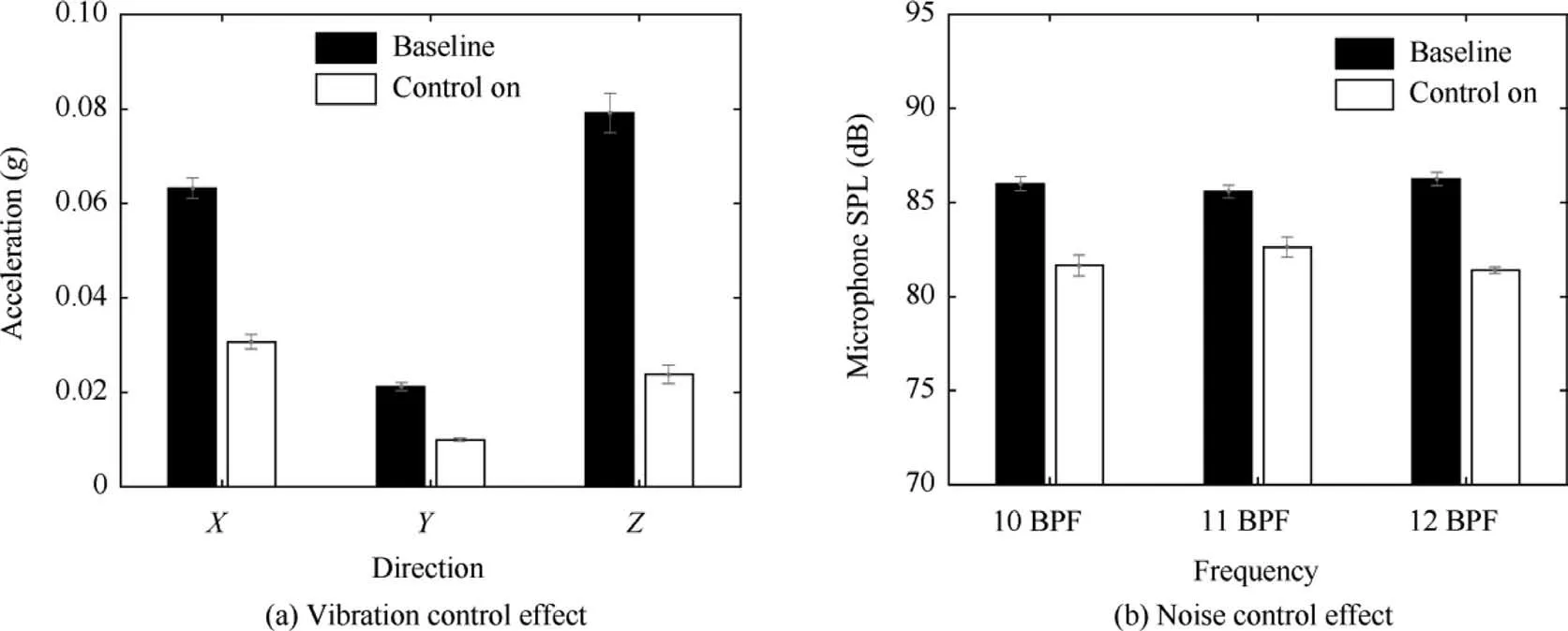
Fig.20 Vibration control effect during wind tunnel test with α=0.999.
4.2.3.Only noise control
Lastly,according to test state 6 in Table 2,a noise control test in wind tunnel condition is carried out.The 2/rev triaxial vibration levels of acceleration sensor 1 are taken as vibration feedback signals.And the 10th,11th and 12th BPF components noise SPL of microphone 5 are taken as the feedback signals of the controller.The 2/rev flaps deflection is taken as control input.The weight coefficient is set as α=0.001 to make the controller focus on noise control.
Fig.21 illustrates the contour of the radiated BVI noise beneath the ECR advancing side.The aft inboard area has the highest BVI noise level.When the control is applied,the SPL in this area is significantly reduced.And the noise SPL measured by microphone 5 is reduced by about 3 dB.

Fig.21 Noise SPL distribution variation beneath ECR advancing side during wind tunnel test with α=0.001.
As shown in Fig.22,when focusing on noise control,the vibration signal only has a small weight in the objective function,but the vibration level of the model ECR is still be reduced.The 2/rev longitudinal vibration is reduced by 5%,2/rev vertical vibration is reduced by 11%,and 2/rev lateral vibration is reduced by 61%.This means the 2/rev flap active control input can reduce the BVI phenomenon of the model ECR,and therefore reduces the vibration and noise level of the rotor simultaneously.
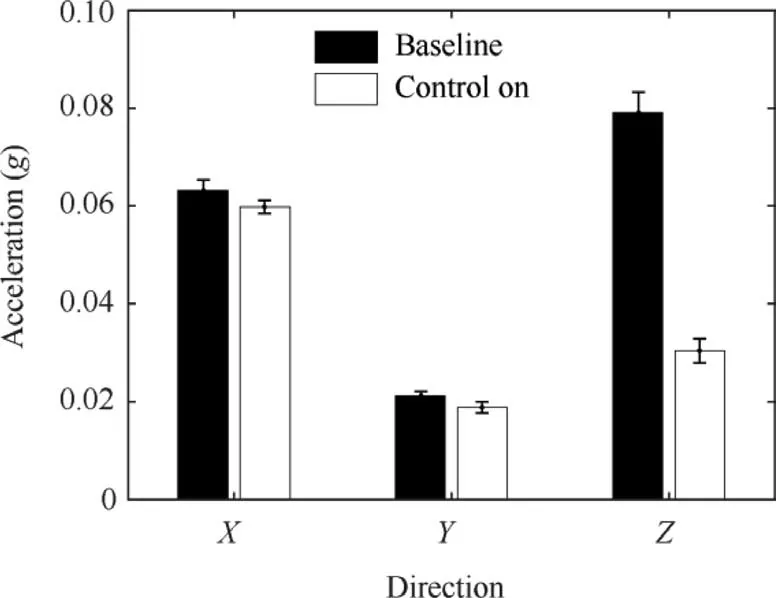
Fig.22 Triaxial vibration variation at acceleration sensor 1 during wind tunnel test with α=0.001.
5.Conclusions
(1) In hover condition the ECR active control is very effective in reducing 2/rev in-plane vibration load in hover condition.It can achieve up to 75% reduction in 2/rev longitudinal vibration.
(2) Proper trailing edge flaps active control can also suppress the rotor thickness noise by introducing an opposite in-plane loading noise,resulting in 5 dB reduction of total in-plane noise.
(3) In hover condition,only vibration control will rise up inplane noise level,and vice versa.But by adjusting the weight coefficients matrix of the control objects,the optimal control inputs for simultaneous control of vibration and noise can be achieved.Up to 54% of 2/rev longitudinal vibration and 9.4 dB in-plane noise can be reduced.
(4) In wind tunnel condition,the 2/rev active flap control input can reduce the BVI event effectively,therefore,the vertical vibration load can be reduced up to 60%with controlling noise only,and the noise SPL at the controlled point can also be reduced by 3 dB.Similar control effect is achieved in only vibration control case.
(5) The multi-frequency active flap control can reduce the BVI event of the model ECR more effectively.In this case,the vertical vibration load can be reduced by 75%,which is 5% higher than the result of only vibration control using single frequency control input.The effect of noise control is equivalent to the result of only noise control.
(6) In wind tunnel condition,vibration load is reduced from the source -reducing BVI event-rather than counteracting the vibration by introducing an extra vibration source.Therefore,the vibration level at the nonfeedback position can also be reduced.
Declaration of Competing Interest
The authors declare that they have no known competing financial interests or personal relationships that could have appeared to influence the work reported in this paper.
Acknowledgments
Authors would like to thank the National Key Laboratory Foundation of China (No.51375229) and Priority Academic Program Development of Jiangsu Higher Education Institutions,China (PAPD).
杂志排行

CHINESE JOURNAL OF AERONAUTICS的其它文章
- Parameter effects on high-speed UAV ground directional stability using bifurcation analysis
- Supersonic flutter control and optimization of metamaterial plate
- Review of in-space assembly technologies
- Utilisation of turboelectric distribution propulsion in commercial aviation:A review on NASA’s TeDP concept
- The influence of inlet swirl intensity and hot-streak on aerodynamics and thermal characteristics of a high pressure turbine vane
- Full blended blade and endwall design of a compressor cascade