Selective Exposure of BiOI Oxygen-Rich {110} Facet Induced by BN Nanosheets for Enhanced Photocatalytic Oxidation Performance
2021-09-01QianZhengYuehanCaoNanjianHuangRuiyangZhangYingZhou
Qian Zheng , Yuehan Cao , Nanjian Huang , Ruiyang Zhang , Ying Zhou 1,,*
1 State Key Laboratory of Oil and Gas Reservoir Geology and Exploitation, Southwest Petroleum University, Chengdu 610500,China.
2 The Center of New Energy Materials and Technology, School of New Energy and Materials, Southwest Petroleum University,Chengdu 610500, China.
Abstract: Photocatalytic oxidation is a promising technology for governing emission of environmental pollutants and managing energy crisis. Typically, the photocatalytic performance of photocatalysts is highly dependent on the type of exposed crystal surfaces. As a semiconductor oxide photocatalyst, the different exposed crystal surfaces of bismuth oxyiodide (BiOI) exhibit different photocatalytic oxidation performances. In this study, we chose BiOI as the model material and provided a novel method to improve the photocatalytic oxidation performance by regulating the main exposed crystal facets. Using boron nitride (BN) nanosheets as the templates, two-dimensional/two-dimensional (2D/2D) BiOI/BN nanocompounds were fabricated via an in situ growth method. Owing to the electrostatic interaction, the positively charged BiOI {001} facets prefer to contact the negatively charged BN {001} facet, thus inducing the exposure of BiOI {110} facets. This was identified via X-ray diffraction and transmission electron microscopy analyses. Compared with BiOI {001} facets, there were more lattice oxygen atoms in the BiOI {110} facets. Thus, the exposure of BiOI {110} facets would promote more surface lattice oxygen atoms exposed on the surface of BiOI, which was confirmed by X-ray photoelectron spectroscopy and density functional theory calculations. To evaluate the photocatalytic oxidation performance of BiOI/BN, the photocatalytic NO oxidation reaction was tested under visible light irradiation (λ > 420 nm). Among all the nanocompounds, the BiOI/BN-1.0:1.4 nanocompound exhibited the best NO oxidation ratio of 44.2%, which was almost 30 times higher than that of pristine BiOI (1.4%). The enhanced photocatalytic activity could be attributed to the following two aspects. One, the successful combination of BN effectively promoted the separation of photogenerated carriers, which was identified by steady-state and time-resolved fluorescence spectra, transient photocurrent responses, and electrochemical impedance spectra. Two, benefiting from the introduction of BN nanosheets, BiOI tends to mainly expose the oxygen-rich {110} facets.As a result, the content of O on the BiOI surface increased from 38.3% to 46.6%. Thus, NO preferred to adsorb on the{110} facets of BiOI nanosheets, which was confirmed by theoretical and experimental results. More importantly, the adsorbed NO spontaneously combined with the lattice oxygen atom of the BiOI (110) surface to form nitrogen dioxide(NO2). These findings can provide a novel strategy to tune exposed oxygen-rich facets by constructing 2D/2D photocatalysts for ensuring efficient photocatalytic oxidation performance.
Key Words: Bismuth oxyiodide; Boron nitride; Photocatalytic oxidation reaction; Oxygen-rich surface;Lattice oxygen
1 Introduction
Photocatalytic oxidation reaction has received great attention for environmental pollutants governance and energy crisis management, such as nitrogen oxides (NOx) removal, carbon monoxide (CO) and alkane oxidation1-6. Oxygen was commonly used as the oxidant due to its green and economic features7,8. Unfortunately, the dissociation of O-O bond needs to overcome a high energy, resulting that the activation of O2is relatively difficult9-11. This significantly restrains the performance of photocatalytic oxidation reaction. Furthermore,the surface lattice oxygen atoms in the metallic oxide could directly take part in the oxidation process12-15. Compared with the broken of O-O bond in O2, O-metal bond could be easier to dissociate4,16-20. Hence, it provides a possibility that surface lattice oxygen might be more beneficial for the occurrence of oxidation reaction compared with O2.
Bismuth oxyhalides (BiOX; X = Cl, Br or I) as metallic oxide are attractive in photocatalytic oxidation reaction due to their particular two-dimensional (2D) layered crystal structure and appropriate band gap21,22. Previous studies suggest that the content of O might be quite different in different exposed facets of BiOX23. Hence, controlling the exposed facets of BiOX could realize the exposure of oxygen-rich surface. In previous studies,Peng24et al. synthesized BiOBr with the exposure of {110}facets by using glucose as the capping agent. Yang16et al.synthesized BiOX with a predominance of {110} exposed crystal facetsviaa green synthesis one-step method, in which polyvinylpyrrolidone (PVP) was used to regulate facet.However, the photocatalytic performance of BiOX is still not satisfied on account of the rapid recombination of photogenerated electron-hole pairs25.To overcome this problem, introducing another material to construct nanocomposite is considered to be a suitable strategy26-30.Meanwhile, recent studies suggest that the introduction of 2D materials could significantly affect the growth of crystal1,27,31.Hence, constructing a nanocomposite with 2D material could not only inhibit the recombination of photogenerated electron-hole pairs, but also realize to expose oxygen-rich facet.
Based on this, we select bismuth oxyiodide (BiOI) as the model material because of the prominent visible light absorption capacity32. Furthermore, boron nitride (BN) is chosen as the representative 2D material to combine with BiOI to construct a 2D-2D nanocomposite1,31,33-36. It is found that BN nanosheets induce the oxygen-rich {110} facets of BiOI to expose.Benefiting from this, NO could be directly oxidized by the surface lattice oxygen atoms, resulting in enhanced photooxidation efficiency.
2 Experiment and calculation section
2.1 Materials
Boric acid (H3BO3, A.R., 99.0%), bismuth nitrate pentahydrate (Bi(NO3)3·5H2O. A.R., 99.5%) were supplied from the Chengdu Kelong Chemical Reagent Corp, China. Urea(CO(NH2)2, A.R., 99.0%) and potassium iodide (KI, A.R.,99.0%) were purchased from the Tianjin Kemiou Chemical Co.,Ltd, China. All the chemicals were analytical reagent grade and did not require further purification to use.
2.2 The synthesis of photocatalysts
The BN sample was synthesized using the method we reported earlier37. The BiOI was prepared by chemical precipitation method at room temperature38. The specific steps were as follows: 0.3519 g KI was dispersed into 100 mL deionized water,then stirred for 1 h to get solution A. 0.485 g Bi(NO3)3·5H2O was dispersed into 100 mL acetic acid (HAc) solution (including 9 mL HAc) and stirred for 1 h to get solution B. Poured solution B into solution A drop by drop to obtain the brick red suspension,and continued stirring for 4 h. After the agitation was stopped,the resulting suspension was aged for 1 h. The samples were filtered and washed with deionized water and ethanol for several times, and dried overnight at 60 °C. BiOI/BN photocatalysts with different mass ratios were prepared by the same process with adding BN into solution A and the schematic illustration of the formation process of BiOI/BN composites was shown in Fig.S1 (in Supporting Information, the same below). The mass ratios of BiOI to BN were kept in 1.0 : 1.8, 1.0 : 1.4, 1.0 : 1.2 and 1.0 :1.0, the samples were named as BiOI/BN-1.0:1.8, BiOI/BN-1.0:1.4, BiOI/BN-1.0:1.2 and BiOI/BN-1.0:1.0, respectively.The specific dosages of all samples were shown in Table S1.
2.3 Characterization
X-ray diffraction (XRD, Bruck D8 Advance, Germany) was used to characterize the phase and crystal structure of the samples. The samples’ morphology and microscopic were obtained by transmission electron microscope (TEM, FEI TECNAI G2 F30, USA). The element binding energy and chemical status of the samples were tested with X-ray photoelectron spectroscopy analyzer (XPS, Thermo ESCALAB 250Xi, USA) and C 1s(284.8 eV) was used as the standard for calibration. The optical absorption was tested by ultravioletvisible diffuse reflectance spectrophotometer (UV-Vis,Shimadzu UV-2600, Japan). The photoluminescence spectra were tested by a fluorescence spectrometer (PL, Hitachi F-7000,Japan) and excited at 420 nm. Steady/transient fluorescence spectrometer was used to measure time-resolved photoluminescence(TRPL, Edinburgh FLS980, UK) which was excited at 420 nm. The 5,5-dimethyl-1-pyrroline N-oxide(DMPO) spin-trapping electron spins resonance (ESR) spectra were characterized by Bruker A300 spectrometer (Germany) in a methanol dispersion for DMPO-·O2−and in an aqueous dispersion for DMPO-·OH, respectively. The samples were irradiated under visible light (λ> 420 nm) by 300 W xenon lamp.
2.4 Photoelectrochemical measurements
The transient photocurrent and electrochemical impedance spectra (EIS) were tested using a standard electrochemical workstation with three-electrode system (CHI660E, Chenhua Instruments Co., Ltd.). 0.5 mol·L−1Na2SO4solution was selected as electrolyte, Pt electrode and saturated calomel electrode (SCE) were used as counter electrode and reference electrode, respectively. The catalysts and ethyl cellulose were evenly mixed in ethanol at a ratio of 10 : 1, then smeared on the surface of ITO glass and dried at 60 °C for 2 h to obtain the working electrode.
2.5 Photocatalytic NO oxidation test
The device for evaluating the performance of photocatalytic NO oxidation was independently constructed, as shown in Fig.S226. The specific operation steps were as follows: two beakers individually held 100 mg samples, which were dispersed with 10 ml deionized water. After ultrasound for 10 min, the samples were transferred to a petri dish. After drying at 60 °C, the samples were put into a reactor and sealed. Then NO (flow rate was 11.3 L·min−1) and dry air (flow rate was 2 L·min−1) were pumped into the reactor. When the concentration of NO in the reactor reached a balance ofca. 0.670 × 10⁻⁹g·m−3, the metal halogen light source was turned on and the filter (> 420 nm) was capped. The photocatalytic performance was tested under visible light illumination (light intensity: 35.88 mW·cm−1). Another empty reactor was used to ensure the initial concentration of NO reached a balance ofca.0.675 × 10−9g·m−3to do the NO adsorption experiment. Then the switch was transferred to the reaction reactor to evaluate the NO adsorption performance of samples at room temperature without light illumination.
The oxidation ratio of NO was calculated as:

in whichCrepresented real-time NO concentration, andC0stood for original NO concentration.
2.6 Computational parameters
In this paper, periodic density functional theory (DFT)computations was operated on the Cambridge Sequential Total Energy Package (CASTEP) code in Materials Studio39. The convergence precision was 0.2 V·nm−1, the energy convergence was set to 2.0 × 10⁻⁵eV·atom-1in the optimization process, the cutoff energy andk-point were set as 380 eV and 2 × 2 × 1,respectively. The vacuum layer thickness was set at 1.5 nm.
The calculation formula of adsorption energy was defined as Formula (2):

Esurface+moleculerepresented the total energy of NO and O2adsorbed on BiOI (001) and (110);Esurfacerepresented the energy of BiOI (001) and (110);Emoleculerepresented the energy of molecular NO and O2.
3 Results and discussion
3.1 Crystal Structure and morphology
The phase and crystal structure of the prepared BiOI, BN (cf.Fig. S3) and BiOI/BN nanocomposites were investigated by XRD analysis. In Fig. 1a, all XRD peaks of the pure BiOI were corresponding to the standard tetragonal phase of BiOI (JCPDS No. 10-0445). For pure BiOI, the strongest two diffraction peaks corresponded to (102), (110) planes appeared at 29.6° and 31.7°,which suggested that the main exposure of BiOI were {001} and{110} facets23,40-42. With the introduction of BN, the diffraction intensity of the characteristic (110) planes had increased, while a reverse trend was observed for (001) planes. To be specific, the diffraction peak intensity ratio between (110) and (102) planes(I(110)/I(102)) was calculated as exhibited in Fig. 1b. It’s found thatI(110)/I(102)of pure BiOI was 0.49. When the nanocomposite constructed, theI(110)/I(102)ratio increased firstly and then decreased with the content of BN increased. BiOI/BN-1.0:1.4 sample revealed the strongestI(110)/I(102)ratio of 2.00, which was almost four times higher than pure BiOI. What’s more, based on the intensity of different planes observed in XRD patterns, the intensity percentages of oxygen-rich (110) plane to the whole main planes of pure BiOI and BiOI/BN-1.0:1.4 nanocomposites were calculated, respectively. The average percentage of oxygen-rich (110) plane increased from 18.32% to 47.4% after the introduction of BN nanosheets. The results indicated that the main exposed facets of BiOI could change to {110} facets after combination with BN32. What’s more, the typical peaks of BN could not be observed in the XRD patterns of BiOI/BN nanocomposites, which might be ascribed to the low diffraction intensity of BN and the random distribution of BiOI on the BN35,43. To verify the existence of BN in the nanocomposite,TEM-EDS mapping of BiOI/BN-1.0:1.4 was applied in the Fig.2. It was noted that the BiOI nanosheets were evenly distributed on the surface of BN nanosheets, proving that BiOI/BN composites were successfully constructed.
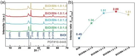
Fig. 1 (a) XRD patterns; (b) intensity ratio of I(110)/I(102) of the obtained pure BiOI and BiOI/BN nanocomposites.
To identify the effect in the microstructure of BiOI after BN introduction, pure BiOI and BiOI/BN nanocomposites were tested by TEM and HRTEM. In Fig. 3a, BiOI presented as nanosheets with diameters of 2-3 μm. The HRTEM image in Fig. 3b revealed that the interplanar spacing observed in pure BiOI nanosheets were 0.28 and 0.20 nm, indexing to the (110)and (200) crystallographic planes of BiOI respectively22,44. The result was consistent with the XRDanalysis. For BiOI/BN-1.0:1.4 sample, there were two kinds of nanosheets stacking together which was observed in the TEM image (cf.Fig. 3c).Combined with the EDS mapping images, it was found that the nanosheets with dark color and lattice fringes belonged to the BiOI, which were distributed onto the transparent BN nanosheets. Meanwhile, the observed lattice spacings for two groups of vertically crossed lattice fringes were 0.28 nm in HRTEM image of BiOI/BN-1:1.4 sample, which were indexed to the (110) and (110) planes, namely {110} facets of BiOI43,45.It could be concluded that BiOI preferred to mainly expose{110} facets instead of both {001} and {110} facets after BN introduction.
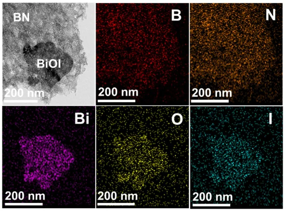
Fig. 2 TEM-EDS element mapping images of BiOI/BN-1.0:1.4.
For probing into the possible growth mechanisms of BiOI which was induced by BN nanosheets, the models of (001) and(110) crystal surfaces were firstly constructed in Fig. 4. It’s found that the outermost exposed atoms of BiOI (001) surface was Bi3+, resulting in the positive charge of surface. However,much more O atoms were exposed on the BiOI (110) surface,leading to the negatively charged, which was reported in previous work1,31,32,36. The Zeta potentials of BN nanosheets was measured to be negatively charged (−35.2 mV) in Fig. S4.Hence, as shown in Fig. 4b, the positively-charged BiOI (001)surface would contact with the negatively-charged BN (001)surface owing to the electrostatic interaction, promoting the exposing of {110} facets31.

Fig. 3 (a) TEM; (b) HRTEM of pure BiOI; (c) TEM and(d) HRTEM of BiOI/BN-1.0:1.4.
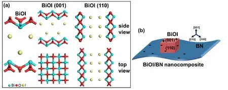
Fig. 4 (a) The section models of (001) and (110) surface of BiOI; (b) schematic diagram of BiOI/BN nanocomposite.
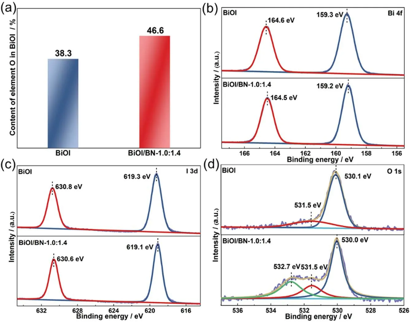
Fig. 5 (a) The contents of element O in BiOI; (b–d) XPS spectra of the BiOI and BiOI/BN-1.0:1.4 nanocomposite.
3.2 Surface compositions
To identify the surface chemical compositions and chemical status, the XPS spectra of as-synthesized BiOI and BiOI/BN nanocomposites were measured in Fig. S5. The extra B and N elements were observed in the survey scan spectra of BiOI/BN-1.0:1.4 compared with that of BiOI, further confirming the successful introduction of BN. The contents of each element in BiOI and BiOI/BN-1.0:1.4 were calculated in Table S2.Furthermore, the contents of element O in BiOI of pure BiOI and BiOI/BN-1.0:1.4 (The contents of elements O, B, N in BN were subtracted) were calculated. Clearly in Fig. 5a, the content of element O in BiOI increased from 38.3% to 46.6% after combining with BN. It was suggested that introducing BN promoted the exposure of BiOI {110} facets, resulting that more O atoms were exposed on the surface compared with pure BiOI.
The high-resolution XPS spectra of BiOI and BiOI/BN-1.0:1.4 were presented in Fig. 5b-d. For BiOI, two strong peaks located at 159.3 and 164.6 eV were consistent with Bi 4f7/2and Bi 4f5/2, respectively. For I 3dspectra, two peaks at 619.3 and 630.8 eV were associated with I 3d5/2and I 3d3/233,43.Meanwhile, two characteristic peaks of O 1sat 530.1 and 531.5 eV were corresponding to the Bi-O bonds in [Bi2O2]2+slabs of the BiOI and the adsorbed water on the surface of samples33,44.The above results indicated the successful fabrication of BiOI.After combined with BN, the characteristic peaks assigned to BN were found in B 1sand N 1sspectra. Besides that, there was a peak appearing at the 532.7 eV in O 1sspectra, which was corresponding to the B-O bonds of BN45. It should be noted that the positions of characteristic peaks in Bi 4fand I 3dspectra moved towards the lower binding energy (ca.0.1 eV) after introducing BN. It was indicated that there was an interfacial interaction between BiOI and BN which was advantageous to the migration of photogenerated carrier.
3.3 Photocatalytic performances
Nitric oxide (NO), as a kind of major atmospheric pollutant,was selected to be the target pollutant to estimate the photocatalytic oxidation performance of the BiOI, BN and BiOI/BN nanocomposites under visible light irradiation (λ> 420 nm) (cf. Fig. 6). Pure BiOI and BN showed neglectable photocatalytic activity for NO oxidation reaction. Quite different from them, NO oxidation ratio was significantly improved after the combination of BiOI and BN. With the increased content of BN, NO oxidation ratio first increased and then decreased.Among them, BiOI/BN-1.0:1.4 exhibited the best NO oxidation ratio of 44.2%, which was almost 30 times than pure BiOI. After illumination for 30 min, the NO oxidation ratio kept at about 42.3%, revealing the good stability.
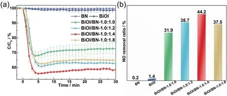
Fig. 6 Photocatalytic activity of BN, BiOI and BiOI/BN nanocomposites for NO oxidation.
3.4 Photocatalytic oxidation mechanism
To understand the reasons for the enhanced photocatalytic oxidation activity of BiOI/BN nanocomposites, these three factors were considered: (1) light absorption; (2) photogenerated carriers separation; (3) surface reaction46. Firstly, the light absorption capacity of the samples was shown in Fig. S6. The pure BN only exhibited absorption capacity in the ultraviolet region. While pure BiOI had a strong absorption in the visible region. With introducing BN, the absorption edges of BiOI/BN nanocomposites had a blue-shifted (ca.60-70 nm)and all samples presented an absorption response for visible light.
To further verify the role of BN in the separation of photogenerated carriers, steady-state and time-resolved PL spectra, transient photocurrent responses and electrochemical impedance spectra of BiOI and BiOI/BN-1.0:1.4 were tested,respectively. In Fig. 7, the intensity of steady-state fluorescence peak for BiOI/BN-1.0:1.4 had decreased compared with the pure BiOI. As for the lifetime of photogenerated carriers, BiOI/BN-1.0:1.4 was increased from 984.7 ns to 1032.1 ns after recombination with BN. What’s more, a higher current density and a smaller arc radius in the Nyquist plots were observed (c.f.Fig. 7c-d) for BiOI/BN-1.0:1.4 compared with pristine BiOI.These results confirmed that the introduction of BN could effectively facilitate the separation of photogenerated carriers.Furthermore, there were more superoxide radical (·O2−) and hydroxyl radical (·OH) generation by BiOI/BN-1.0:1.4 under visible light compared with pristine BiOI, as shown in Fig. S7.This was further proved the effective separation of photogenerated carriers, which could be beneficial for the photocatalytic performance.
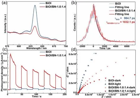
Fig. 7 The (a) steady-state; (b) time-resolved PL spectra (excited at 420 nm); (c)transient photocurrent response;(d) electrochemical impedance spectra (EIS) of BiOI and BiOI/BN-1.0:1.4 nanocomposites.
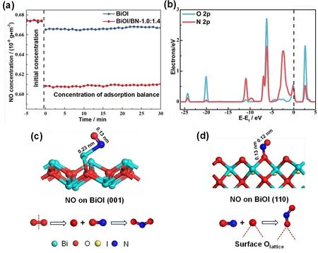
Fig. 8 (a) NO adsorption performance of BiOI and BiOI/BN-1.0:1.4; (b) The PDOS of NO adsorption on BiOI (110) surface, the black dotted line indicate the Fermi level; the optimized structure and the possible reaction paths of NO adsorbed on BiOI (d) (001) surface; (c) (110) surface.
To identify the effect of different exposed crystal surface in surface reaction, the NO adsorption experiment at room temperature without light illumination over BiOI and BiOI/BN-1.0:1.4 were performed firstly. As shown in Fig. 8a, after 30 min for NO adsorption on pure BiOI, the concentration of NO decreased from 0.674 to 0.667 × 10⁻⁹g·m−3, indicating its poor adsorption performance. Quite different from BiOI, the NO adsorption was significantly improved after the combination of BN. BiOI/BN-1.0:1.4 exhibited the NO adsorption capacity of 0.070 × 10⁻⁹g·m−3, which was almost 7 times than pure BiOI.These results proved that the exposure of BiOI oxygen-rich{110} facets promoted the adsorption ability of NO. For probing into the possible NO oxidation reaction paths on the (001) and(110) surface of BiOI, the adsorption of O2and NO on (110) and(001) surfaces of BiOI were simulated in Fig. 8 and Table S3.The energies of NO and O2adsorbed on BiOI (001) surface were−2.73 eV and −4.31 eV, respectively. It was indicated that O2might prefer to adsorb on BiOI (001) surface than NO. Inversely,compared with O2, NO was more likely to adsorb on BiOI (110)surface because of the more negative adsorption energy of −2.75 eV. According to the partial density of states (PDOS) in Fig. 8b,the O 2pof lattice O atom inBiOI (110) surface and N 2pof N atom in NO molecule were strongly hybridized at −6.95, −6.23,−0.16 and 2.66 eV, which indicated that NO molecule was bonded with the lattice O atom of BiOI (110) surface to form the O-N-O intermediate. As presented in Fig. 8d, it is observed that the bond lengths of the O-N-O intermediate were 0.12 nm and 0.13 nm and the bond angle was 117.63°, which were similar to original molecular NO2. The above results suggested that after NO molecule adsorbed on the BiOI (110) surface, it would combine with the lattice O atom to directly convert into NO2.Based on these results, two different NO oxidation reaction paths could be speculated on the (001) and (110) surface of BiOI (cf.Fig. 8c,d). On BiOI (001) surface, O2would firstly attach to the surface to dissociate into two activate O atoms, which was difficult to take place due to the high dissociation energy of the OO bond25. Then, the adsorbed NO would be oxidized by the dissociated O atom to generate NO2. However, on BiOI (110)surface, the preferred adsorbed NO would spontaneously combine with the surface lattice oxygen to directly convert into NO2.
4 Conclusions
In summary, 2D/2D BiOI/BN photocatalysts were successfully fabricated byin situgrowing BiOI nanosheets over the surface of BN nanosheets. On one hand, the successful combination of BN effectively promoted the separation of photogenerated carriers. More importantly, BiOI inclined to mainly expose {110} facets, which was induced by BN. The exposure of {110} facets promoted that the content of O on BiOI surface increased from 38.3% to 46.6%. Hence, the adsorbed NO would spontaneously combine with the lattice oxygen atom of BiOI (110) surface to directly convert into NO2. As a result,BiOI/BN-1.0:1.4 exhibited a high NO oxidation ratio of 44.2%under visible light irradiation (λ> 420 nm), which was almost 30 times more than pure BiOI (1.4%).
Acknowledgment:Ying Zhou gratefully acknowledges the financial support from Cheung Kong Scholars Programme of China.We acknowledge the National Supercomputing Center in Shenzhen for calculation support.
Supporting Information:available free of chargeviathe internet at http://www.whxb.pku.edu.cn.
杂志排行

物理化学学报的其它文章
- Defect Engineering in Two-Dimensional Graphitic Carbon Nitride and Application to Photocatalytic Air Purification
- 理论计算评价光催化剂VOCs 降解性能:g-C3N4 量子点/石墨烯
- 富含缺陷的2D/2D 异质结促进光催化清洁能源转化
- Development of Iron-Based Heterogeneous Cocatalysts for Photoelectrochemical Water Oxidation
- 二维光催化材料电子结构和性能调控策略研究进展
- Non-Noble-Metallic Cocatalyst Ni2P Nanoparticles Modified Graphite-Like Carbonitride with Enhanced Photocatalytic Hydrogen Evolution under Visible Light Irradiation