Robust Controller Synthesis and Analysis in Inverter-Dominant Droop-Controlled Islanded Microgrids
2021-07-26MohsenAzizi
S. Mohsen Azizi,
Abstract—This work investigates the problem of controller design for the inverters in an islanded microgrid. Robust µ-synthesis controllers and local droop controllers are designed to regulate the output voltages of inverters and share power among them, respectively. The designed controllers alleviate the need for additional sensors to measure the states of the system by relying only on output feedback. It is shown that the designed µ-synthesis controller properly damps resonant oscillations, and its performance is robust to the control-loop time delay and parameter uncertainties. The stability of a droop-controlled islanded microgrid including multiple distributed generation(DG) units is analyzed by linearizing the nonlinear power flow model around the nominal operating point and applying theorems from linear algebra. It is indicated that the droop controller stabilizes the microgrid system with dominantly inductive tie-line impedances for all values of resistive-inductive loads, while for the case of resistive-capacitive loads the stability is conditioned on an upper bound on the load susceptances. The robust performance of the designed µ-synthesis controller is studiedanalytically,comparedwiththe similar analysis inanH∞control(benchmark) framework,andverified by simulationsfor a four DG benchmark microgrid. Furthermore, the robustness of the droop controllers is analyzed by Monte Carlo simulations in the presence of local voltage fluctuations and phase differences among neighboring DGs.
I. INTRODUCTION
THE application of renewable energy resources such as wind turbines and photovoltaic units has significantly grown in the past decade. The interface between these renewable energy resources and the utility grid is handled by inverters. In order to satisfy the power quality standards specified by IEEE Standard 1547, the output current of an inverter needs to be filtered using passive filters such as L,LC, and LCL filters which eliminate the switching frequency harmonics [1]–[7]. Compared to an L filter, LC and LCL filters are cheaper, less costly, smaller in size, and more effective in terms of attenuation. But these high-order filters generate undesired resonances, which make the controller design problem more challenging to sufficiently damp them[8]–[10]. Adding additional resistance to the output filter,which is considered as a “passive damping” approach,increases the system loss and hence decreases efficiency [11].The alternative approach is called “active damping”, which attenuates the undesired resonances by using a control feedback loop [8], [12], [13].
Various techniques in the literature have addressed the problem of output voltage control for an off-grid inverter.Different multi-loop linear control schemes are investigated and compared in [14] for single-phase inverters, and their steady-state errors are investigated under different loading conditions. A decentralized control method based on P and Q droop characteristics is utilized in [15] for inverter-based islanded microgrids. A load compensator is employed in [16]for harmonic current filtering and resonance damping in an islanded microgrid based on the decomposition of output current. An oscillator-based inverter control technique is proposed in [17] for islanded microgrids, where the dynamics of a nonlinear oscillator is emulated by programming the output of each inverter. A neutral-point voltage balancing method is developed in [18] for a three-level inverter by using a discontinuous pulse width modulation technique. An adaptive droop control technique is applied in [19] to the problem of inverter voltage control that can operate both in the grid-connected and off-grid modes. An adaptive voltage control technique is proposed in [20] for three-phase off-grid inverters. A model predictive control technique is developed in [21] and applied to the problem of voltage control in standalone inverters.
In [22], a decentralized robust mixedH2/H∞control technique is proposed for autonomous/islanded voltagesourced converter (VSC) based microgrids. This control system is designed for set point tracking and disturbance rejection. It also enhances the fault-ride through capability of a microgrid and its performance subject to small and large signal disturbances and nonlinear loads. In [23], a robust hierarchical control strategy is proposed for off-grid autonomous VSC-based AC microgrids. In [24], a descriptor systemH∞approach is proposed to improve the performance of robustH∞controller, and a decentralized robust servomechanism control strategy is implemented for an autonomous VSC-based microgrid that consists of multiple distributed generation (DG) units. In [25], a unified, robust hierarchical control scheme is proposed for networked DG grid-forming power converters in islanded AC microgrids.The main control level stabilizes the frequency and voltage of an AC microgrid via a cascaded configuration which consists of a droop controller, a mixedH2/H∞-based voltage controller, and an adaptive backstepping integral nonsingular fast terminal sliding mode control for current loop. In [26],authors present a new decentralized robust strategy to ameliorate small and large signal stability and power sharing of a hybrid AC/DC microgrid, and improve its performance for nonlinear and unbalanced loads. In [27], a new decentralized robust power/current/voltage/frequency control scheme for islanded and grid-connected modes is designed to ameliorate power-sharing and small and large signal stability of a wind/photovoltaic/fuel cell microgrid and enhance its performance for nonlinear and unbalanced loads.
In [28], an optimal and robust nonlinear control strategy is proposed to achieve trajectory tracking of disturbed nonlinear systems, which is applied to the control of power converters in DC microgrids. In [29], a Lyapunov based decentralized control strategy is presented to ensure a proper voltage regulation and power/current sharing performance for singlephase parallel inverters in an islanded micro-grid. In [30], a novel control scheme is presented to perform the exact finitetime restoration among voltages and frequencies of an islanded inverter-based microgrid. Ad-hoc chattering-free sliding-mode based distributed algorithms are designed to improve the underlying robustness and convergence properties of the system. In [31], the application of a finite control set model predictive control technique is studied for standalone AC microgrids including multiple VSCs with the capability to modulate the voltage at the point of common coupling, while balancing and sharing loads among them.
The problem of balanced power sharing among DG units has been conventionally tackled by a droop control technique.However, in the general case of multiple DGs in a microgrid,the stability analysis of the overall droop-controlled microgrid is still a challenging problem. This problem is shown in [32]to be equivalent to the semi-stability problem of a class of second-order matrix systems. To investigate the microgrid stability, the work [33] presents a generalized analytical impedance model of a microgrid. In [34], the DGs in an islanded microgrid are modeled as ideal voltage sources, and the analytical stability conditions are provided as a function of the model parameters by conducting a nonlinear analysis. In[35] a two-level distributed control scheme is presented for multiple-bus microgrids based on consensus-based power sharing algorithm, discrete-time droop equation, and Lyapunov-based decentralized control algorithm. The highlevel controllers calculate the voltage references, and the lowlevel controllers make the bus voltages track the voltage references.
In [36], a mathematical model for islanded microgrids with linear loads and inverters under frequency and voltage droop is constructed in a state-space form, and the singular perturbation technique is used to obtain reduced-order models that simplify the stability analysis of microgrids. In [37], a new modeling approach for inverter-dominated microgrids by using dynamic phasors is presented, which is able to accurately predict the stability margins of the system, while the conventional reduced-order small signal model fails. In[38], the small-signal technique is used to adjust droop gains to ensure stability. The small-signal technique is also used in[39] along with eigenvalue analysis to study the frequency stability of a droop-controlled wind turbine in a microgrid. In[40], the dynamic coupling between a DG unit and the host microgrid is altered by using an adaptive feedforward compensator in the presence of droop coefficients. Moreover,the system stability is enhanced for the case of network dynamic uncertainties. In [41], it is indicated that using a high-gain angle droop controller for load sharing disturbs the overall stability, which is shown to be improved by a supplementary loop around the droop control loop. A port-Hamiltonian approach is used in [42] for a loss-less microgrid,and the local stability of microgrids is guaranteed by deriving a sufficient condition.
In [43], a novel nonlinear droop control schemes is proposed to improve the load-sharing accuracy among the parallel-connected voltage-controlled sources and to ameliorate the DC bus voltage regulation in a smart grid system. In [44], a load current sharing control scheme for a DC microgrid is proposed that uses a piecewise linear formation to adaptively tune droop gains in order to balance load sharing among DGs subject to bus voltage deviations. In[45], the lack of decoupling ability for traditional droop control scheme is taken as a motivation to propose an improved droop control strategy that consolidate the coupling compensation and virtual impedance to enhance the efficiency and stability of the microgrid. In [46], the role of droop controller in transient and steady state frequency regulation of a wind turbine is studied, and an efficient droop-based control is proposed which can be tuned independent from the wind speed value.
In [47], a novel repetitive controller is proposed to reduce the negative impact of nonlinear characteristics of variable loads on the output voltage of an AC microgrid. In [48], a systematic approach for the design of structured dynamic output feedback control is proposed for an islanded microgrid.A convex optimization problem is solved which leads to a low-order dynamic controller of arbitrary structure such that the microgrid channels are all decoupled in the presence of load uncertainties. In [49], a state feedback primary control scheme for microgrids is proposed which enhances their transient behavior in both islanded and grid-connected modes of operation. In [50], an optimal and robust model predictive controller is designed for a hybrid energy storage system in a naval DC microgrid application.
In this paper, the control problem for inverters in an islanded microgrid is solved by proposing robust controllers in the µ-synthesis framework, and implementing droop controllers that share active and reactive powers among the inverters. It is analytically verified that the µ-synthesis controllers guarantee robust performance and resonance damping in the presence of control-loop time delay, parameter uncertainties, and undesired disturbances. Moreover, analytical comparison is made between the robust performance of the proposed controller in µ-synthesis framework andH∞control(benchmark framework) that verify the superiority of the proposed approach. In addition, the stability and robustness analyses of the droop-controlled islanded microgrid (with dominantly inductive tie-line impedances) are performed by using eigenvalue condition (on the linearized model of the microgrid) and Monte Carlo simulation, respectively.
In this work, the objective is to propose an approach for controller design and robustness analysis in inverter-dominant droop-controlled islanded microgrids. To the best of our knowledge of the literature, the following unsolved problems still exist which motivate the analytical work developed in this work:
1) The problem of designing a controller for inverters that is robust against various uncertainties and time delays, and also satisfies the performance criteria associate with reference signal tracking and harmonics damping, has not been fully addressed by the current approaches in the literature yet. Such a controller can considerably improve the performance of inverters in practice where uncertainties and time delays result in a significant performance degradation.
2) A “linear” technique that provides a stability analysis and design criterion for droop gains has not been available in the literature yet. Nonlinear techniques are mathematically sophisticated and normally based on restrictive assumptions that are not applicable to all systems in practice. A linear technique based on linear stability criterion (eigenvalue condition) can considerably facilitate and accelerate the design and analysis process of droop gains.
3) The robustness analysis of droop controllers against voltage amplitude and phase variations has not been tackled by the current techniques in the literature yet. In practice,these changes can considerably impact the performance of a microgrid, and hence a comprehensive robustness analysis is required to guarantee the desired performance of a microgrid subject to operating point variations.
To this end, the contributions of the paper as compared to the literature are summarized as follows:
1) The µ-synthesis technique is used to design a controller for inverters to achieve a robust performance against the uncertainties in LC filter components and control-loop time delay values, and satisfy the performance criteria including main frequency tracking and odd harmonics damping.
2) The eigenvalue analysis is performed for droop controllers to find a criterion on the susceptance of a local resistive-capacitive load, which guarantees the stability of the overall droop-controlled closed-loop microgrid system.
3) Extensive Monte Carlo simulations are conducted to analyze the robustness of the droop controllers to voltage variations of local DGs and phase differences between neighboring DGs, and find the associated upper limits to guarantee stability.
The paper is organized as follows. Section II includes the background information on a diagonally dominant matrix, a droop-controlled off-grid inverter model, and the linearized power flow model. Section III includes the parameter uncertainties of an inverter, time delay uncertainty, control performance specifications, and robust controller design in aµ-synthesis framework. In Section IV, the stability of droopcontrolled islanded microgrids is analyzed. The effectiveness and robust performance of the proposed robust inverter controller are verified, and the stability and robustness of droop controllers are analyzed by simulations in Section V.Finally, the paper is concluded in Section VI.
II. BACkGROUND INFORMATION
A. Diagonally Dominant Matrix
The following result is due to [51].

B. Droop-Controlled Off-Grid Inverter Model
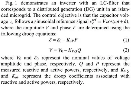

Fig. 1. An inverter with LC filter.
The dynamics of an inverter is governed by

Using (3), the block diagram of the system is displayed in Fig. 2, whereMandGdel=e-T srepresent the inverter gain and the transfer function of aT(sec) time delay, respectively.
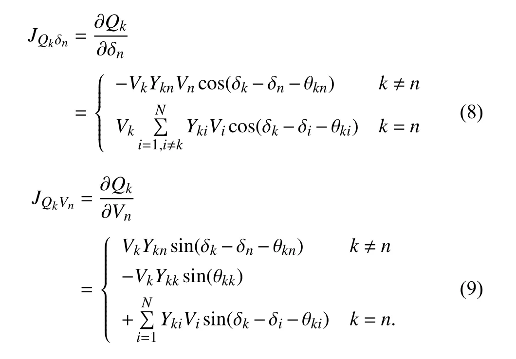
C. Linearized Power Flow Model
In this subsection, the admittance matrix (4) is presented for a power system, based on which the nonlinear power flow equations are linearized in the form of (5) with the Jacobians(6)–(9).


Fig. 2. Block diagram of the dynamic equation (3) of the inverter in Fig. 1.

III. INVERTER MODEL UNCERTAINTIES, PERFORMANCE CONSTRAINTS, AND CONTROLLER DESIGN
In this section, an off-grid inverter is considered and its LC filter uncertainties (12) and (13), time delay uncertainties (19),and performance constraints (20)–(22) are modeled in the µ-synthesis framework as demonstrated in Fig. 3. Moreover, a robust controller is designed using Algorithm 1 to satisfy the robust control, stability, and performance conditions(25)–(27).
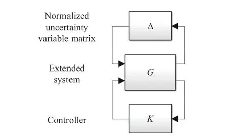
Fig. 3. µ-synthesis framework: Δ /G/K structure.
A. LC Filter Uncertainties


Fig. 4. Expanded block-diagram including the LFTs in (12), (13), and (19), and the performance weights in (20) and (21).


B. Time Delay Uncertainty
The transfer functionGdel(s)=e-T srepresents aT(sec) time delay, whose approximated first-order linear transfer function is

Fig. 5.Dashedlines:transfer functions ; Bold line: transfer functionWdel(s)in (17).
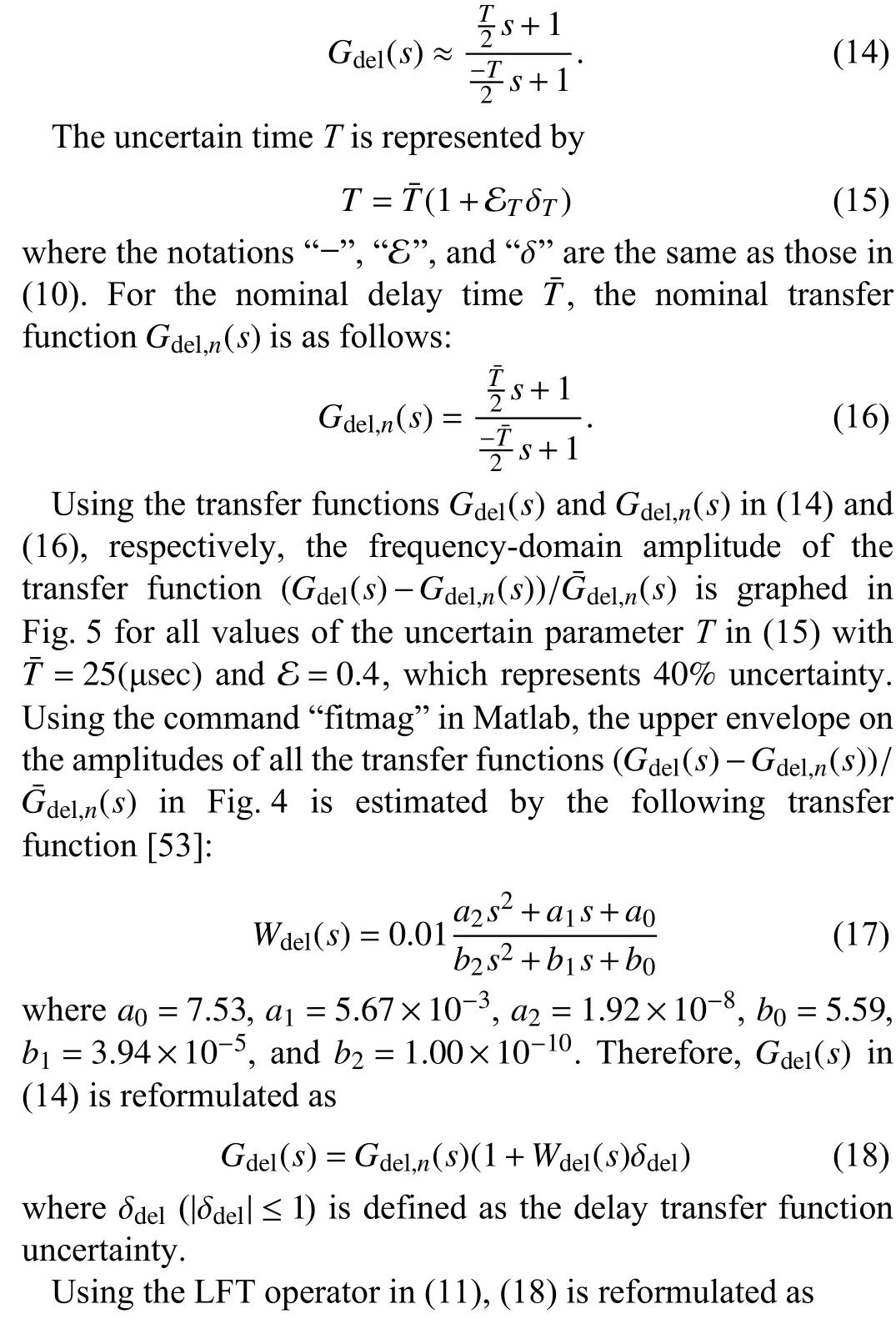

Gdel(s) in (19) is used to transform the block diagram in Fig. 2 into the expanded one in Fig. 4.
C. Performance Constraints

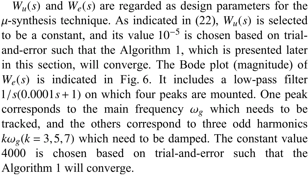

Fig. 6. Bode plot (magnitude) of weight transfer function W e(s).
D. Robust Controller Design Using µ-Synthesis
In this subsection, the expanded block diagram of an inverter with an LC filter demonstrated in Fig. 4 is transformed into a Δ/G/Kstructure [54] in the µ-synthesis framework as depicted in Fig. 3. Moreover, the robust control,stability, and performance conditions (25)–(27) are presented.In addition, the left and right scaling matrices in (28) are used to find an upper bound in the optimization problem (29),which is solved iteratively by using Algorithm 1 in order to design a robust controller in the µ-synthesis framework.
In Fig. 4, the normalized uncertainty matrix Δ has the following structure, where diag(···) represents the blockdiagonal operator:
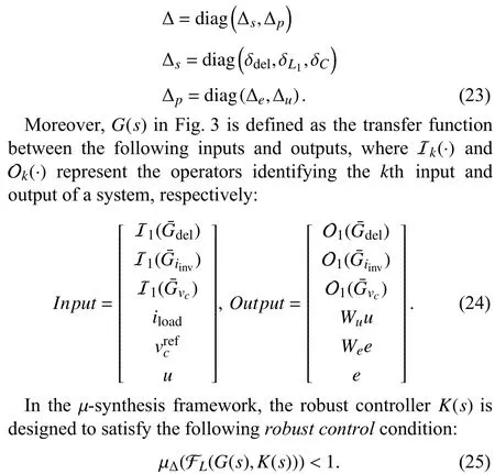
The robust control condition (25) guarantees the stability,robustness, and performance of the designed controller (refer to [54] for the proof), and is a combination of therobust stabilitycondition in (26), whereO2×2represents a 2×2 zero matrix, and therobust performancecondition in (27), where FL(·,·) and FU(·,·) represent the lower and upper LFT operators, respectively, as follows [54]:


Algorithm 1: To find the robust controller , the upper bound for in (29) is minimized by using the D-K iteration algorithm (Matlab command “dkit”), which includes six iterative steps as follows [54]:K(s)µΔ(FL(G(s),K(s)))1) For system , initialize controller by designing an controller.G(s) K(s) H∞2) Calculate the lower linear fractional transformation (LFT).FL(G(s),K(s))3) Determine the frequency range of interest for the control loop,and select N frequencies , , which are uniformly distributed within the frequency range. At each , find the optimum scaling factors , , to replace for in (28) and construct the scaling matrices and to minimize ωn n=1,...,N ωn ˆdk(ωn) k=1,...,5 dk(s)ˆDl(ωk) ˆDr(ωk)σmax(ˆDl(ωn)FL(G(jωn),K(jωn))ˆD-1r (ωn)).4) Estimate the transfer function , , such that, and for all , .represents the set of all stable real rational transfer functions with no poles on the -axis.H∞ K(s)dk(s) k=1,...,5 dk(s),d-1 k (s)∈RH∞ |dk(jωn)|≈ˆdk(ωn) ωnn=1,...,N RH∞jω 5) Design an controller for the following system:■■■■■■Dl(s) 0 0 1■■■■■■G(s)■■■■■■Dr(s) 0 0 1■■■■■■-1.6) If and are close to their previous estimates, then stop;otherwise, go to Step 2.Dl(s) Dr(s)
The runtime overhead of Algorithm 1 is in the order of a few seconds and hence is not significant due to the fact that the controllers are designed offline. In general, Algorithm 1

IV. STAbILITY ANALYSIS OF DROOP-CONTROLLED ISLANDED MICROGRIDS
In this section, Assumption 1 is made and justified in order to transform the Jacobians (6)–(9) into (34)–(37). The vectors(38) and matrices (39) are defined to formulate the concatenated dynamic model (40) which includes all the linearlized power flow equations. Moreover, all droop equations are concatenated in (41). Finally, Theorem 2 is presented to analyze the stability of the overall droopcontrolled islanded microgrid (40) subject to the overall droop controller (41).
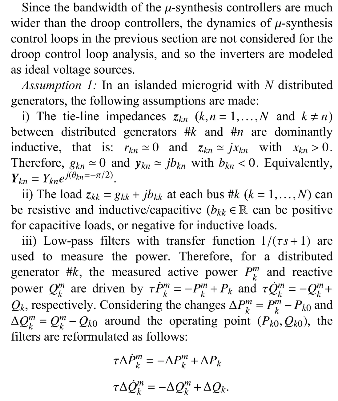
Assumption 1-i) is due to the fact that in highly dispersed power networks, the tie-line impedances are predominantly inductive [55]. In networks spread over a smaller area, the impedances are still inductive but also have a resistive component. However, in such networks, the inductive virtual impedance technique can be used in the converter output current feedback so that the resistive component becomes negligible as compared to the overall inductive component(including the virtual inductance), and so the conventional droop schemes will remain applicable [56]. Assumption 1-ii)does not impose any restrictions on the system, but rather generalizes the loads to both resistive-inductive and resistivecapacitive cases. Assumption 1-iii) is due to the fact that the calculation of power is done by integrating the product of voltage and current signals, for which the magnitude and phase of the integrator are compensated by adding a low-pass filter [57], [58].

The linearized power system models in (5) are concatenated with the dynamic equations of the low-pass filters in Assumption 1-iii). To this end, the following vectors and matrices are defined, where Λ is a 2N×2Ndiagonal matrix with τ on all of its diagonal entries:


V. SIMULATION RESULTS
A. Design and Robustness Analysis of µ-Synthesis Controllers for Inverters

In the following, Figs. 7–14 depict the acceptable stability and performance, and hence justify the efficiency of the µ-synthesis robust controllerK(s) designed for the inverters in this paper.

Fig. 7. Tracking performance for the inverter without uncertainties.

Fig. 8. Tracking performance for the inverter with component value uncertainties.
Fig. 7 demonstrates the tracking performance for the designed inverter controller with nominal parameter values(without any uncertainties).
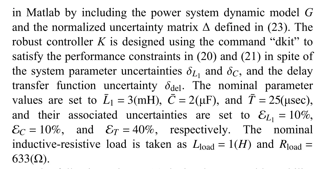
Fig. 8 demonstrates the tracking performance for the designed inverter controller with component value uncertainties including 10% decrease inCandL1,30%decrease inRload, and 5 0% decrease inLload.
Fig. 9 demonstrates the tracking performance for the designed inverter controller with 20% increase in the controlloop time delayT.

Fig. 9. Tracking performance for the inverter with time delay uncertainty.
Similar to µ-synthesis technique,H∞control is also based on the singular values and infinity norm of a transfer function,except that the latter deals with unstructured uncertainties while the former tackles structured uncertainties. Therefore,H∞control is conventionally used as a benchmark for comparison with µ-synthesis technique [54]. To this end, Fig. 10 demonstrates that the µ-synthesis robust control conditionµΔ(FL(G(s),K(s)))<1 in (25) is satisfied, while theH∞control condition |FL(G(s),K(s))|∞<1 (benchmark framework) does not hold and hence cannot verify and guarantee the stability and performance of the designed robust controller.This figure justifies the effectiveness of the µ-synthesis framework.
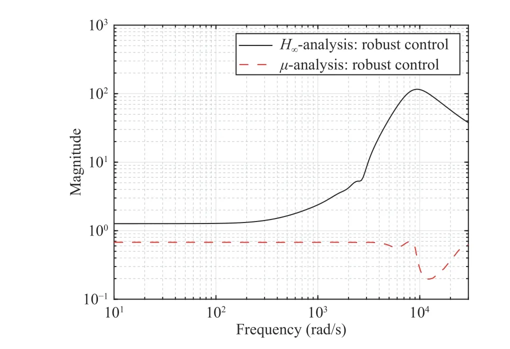
Fig. 10. Comparison of the robust control condition (25) in a µ-synthesis framework with that of an H ∞ control (benchmark framework).
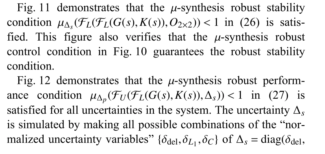

Fig. 11. µ-synthesis robust stability condition in (26) versus robust control condition in (25).
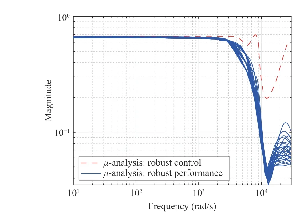
Fig. 12. µ-synthesis robust performance condition (27) versus robust control condition in (25).

Fig. 13 demonstrates that the performance criteriaGu(s)Wu(s)<1 in (20) (for Δu=1) is satisfied for all uncertainties in the system. The uncertainty Δsis simulated in the same way as for Fig. 12.
Fig. 14 demonstrates that the performance criterionGe(s)We(s)<1 in (21) (for Δe=1) is satisfied for all uncertainties in the system. The uncertainty Δsis simulated in the same way as for Fig. 12.
It should be noted that the µ-synthesis controller is designed individually and independently for an inverter, and so there is no need to study its scalability.
B. Stability Analysis of Droop-Controlled Islanded Microgrid

Fig. 13. Robust performance condition G u(s)Wu(s)<1 in (20).

Fig. 14. Robust performance condition G e(s)We(s)<1 in (21).
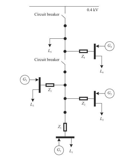
Fig. 15. The four DG benchmark microgrid [59].

The microgrid system is modeled in Matlab/Simulink and simulated using the OPAL-RT real-time simulator. The simulation results are demonstrated in the following Figs. 16–18 in order to validate the stability condition derived in (44).
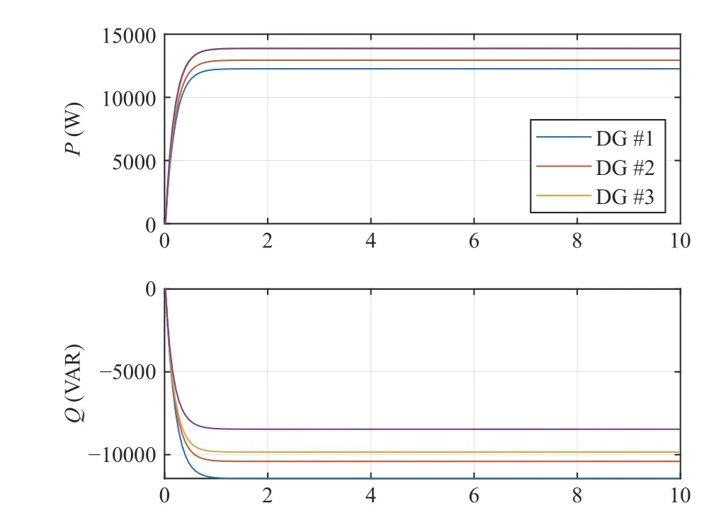
Fig. 16. Active (P) and reactive (Q) powers for the four DG benchmark microgrid with the loads in (45) which satisfy the stability condition in (44).
Fig. 16 demonstrates that the active and reactive powers are properly balanced by the droop controller gains for the four DG units with the resistive-capacitive loadsL1,L2,L3,L4, andL5in Fig. 15 with values specified in (45), which satisfy the stability condition in (44).
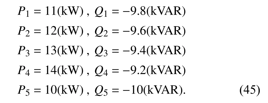
Fig. 17 demonstrates that the active and reactive powers are properly balanced by the droop controller gains for the four DG units with the resistive-capacitive loadsL1,L2, andL3in Fig. 15 with values specified in (46), which marginally satisfy the stability condition in (44).

Fig. 18 demonstrates that the active and reactive powers are not properly balanced by the droop controller gains for the four DG units with the resistive-capacitive loadsL1,L2, andL3in Fig. 15 with values specified in (47), which violate the stability condition in (44).
Therefore, the simulation results in Figs. 16–18 confirm the validity of the analytical condition derived in (44) for the stability of a microgrid subject to capacitive load variations.
C. Robustness Analysis of Droop-Controlled Islanded Microgrid

Fig. 17. Active (P) and reactive (Q) powers for the four DG benchmark mircogrid with the loads in (46) which marginally satisfy the stability condition in (44).
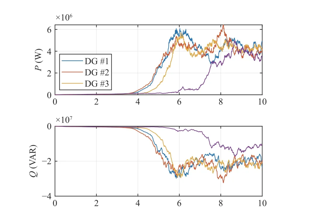
Fig. 18. Active (P) and reactive (Q) powers for the four DG benchmark microgrid with the loads in (47) which violate the stability condition in (44).

Consider (42) in the following compact form:

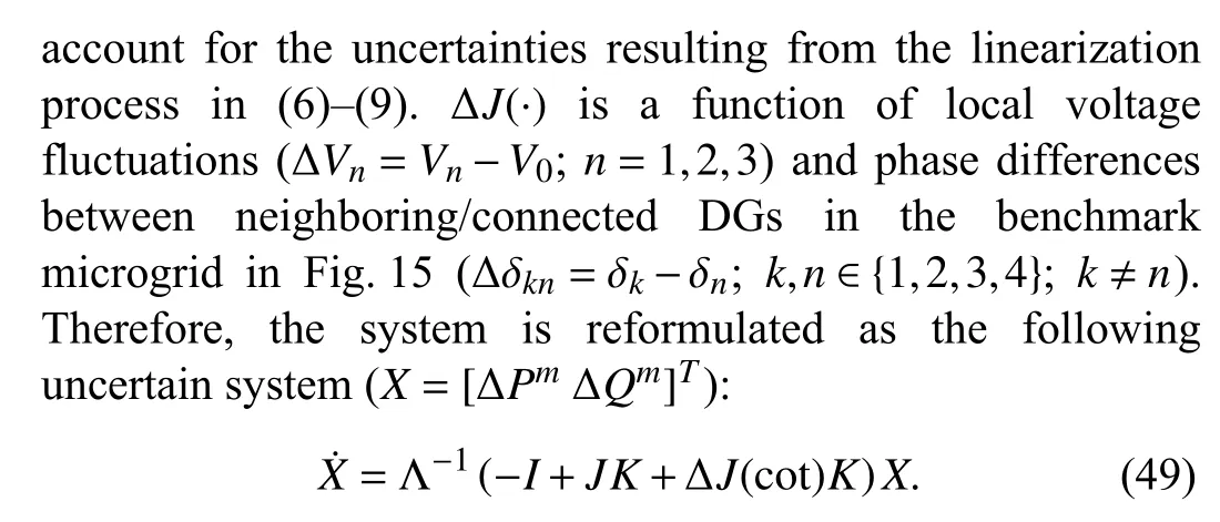
The matrixJin (48) is replaced byJ+ΔJ(·) in order to
In the following, Monte Carlo simulations are conducted in Matlab for robustness analysis of the droop-controlled islanded microgrid. Different values of δnandVn,n=1,2,3,4 are used to find the upper limitsLδin |Δδkn|<LδandLVin|ΔVn/V0|<LV, which guarantee the stability (based on the eigenvalue condition) of the uncertain system in (49). Figs. 19–21 present the Monte Carlo robustness analysis of the droopcontrolled islanded microgrid that will determine the upper limitsLδandLV.
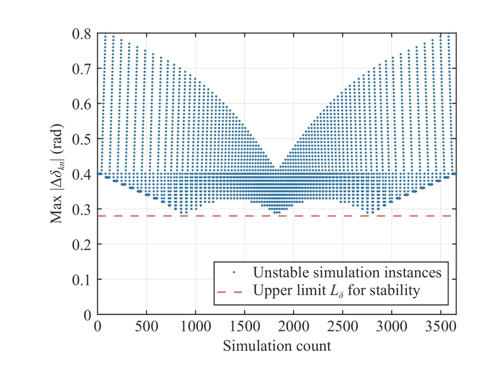
Fig. 19. Monte Carlo simulations for different values of δn, n =1,2,3,4,and fixed and equal values of V n.
Fig. 19 demonstrates the Monte Carlo simulations for different values of δn,n=1,2,3,4, changing arbitrarily around the nominal value (zero here), while the values ofVnare fixed at the nominal operating pointV0. In this figure, only the unstable simulation instances are pinpointed, and the simulation count is represented by the horizontal axis. The vertical axis represents the maximum |Δδkn|=|δk-δn| among the three values |Δδ12|, |Δδ23|, and |Δδ34|. The upper limit|Δδkn|<Lδ=0.28(rad)≃16(deg), which guarantees stability of the uncertain system in (49), is indicated by the red line.
Fig. 20 demonstrates the Monte Carlo simulations for different values ofVn,n=1,2,3,4, changing arbitrarily around the nominal operating pointV0, while the values ofδnare all fixed at the nominal value. In this figure, only the unstable simulation instances are pinpointed, and the simulation count is represented by the horizontal axis. The vertical axis represents the maximum|ΔVn/V0|=|(Vn-V0)/V0|among the four values |ΔV1/V0|, |ΔV2/V0|, |ΔV3/V0|, and|ΔV4/V0|. The upper limit |ΔVn/V0|<LV=0.14 (14%variation around the nominal operating pointV0), which guarantees stability of the uncertain system in (49), is indicated by the red line.

Fig. 20. Monte Carlo simulations for different values of Vn, n=1,2,3,4,and fixed and equal values of δn.

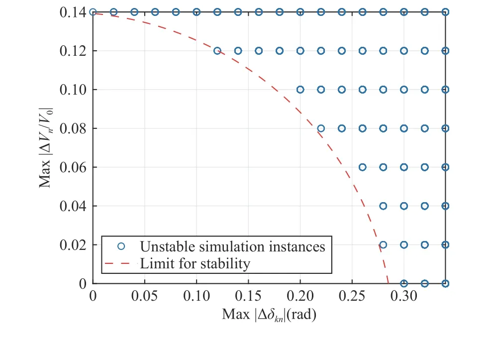
δn Vn n=1,2,3
Fig. 21. Monte Carlo simulations for different values of and ,.
In order to verify the scalability of the results in this section,Monte Carlo simulations are extended to the cases of up to ten generators. Fig. 22 demonstrates the achieved stability upper limitsLδandLV, which converge to 0.26(rad) and 0.13,respectively.
D. Discussions
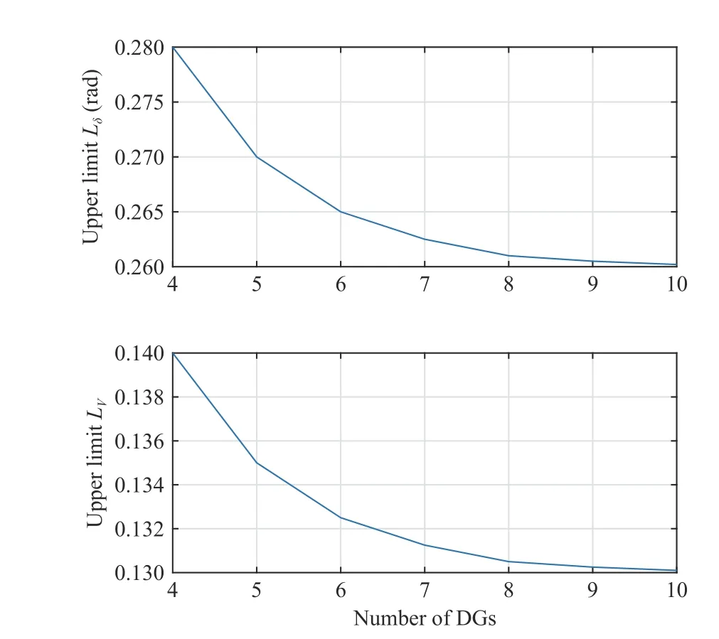
Fig. 22. Extended Monte Carlo simulations for upper limits Lδ and LV for up to ten generators.
In Section V-A, a robust controller is designed for inverters.Figs. 7–9 demonstrate the time-domain performance and robustness of the designed controller against uncertainties in the load, LC filter component, and time delay values.Moreover, Figs. 10–14 verify the frequency-domain criteria which are regarded as proof of stability, robustness, and performance of the controller [54].
In Section V-B, Figs. 16–18 validate the stability condition derived analytically in (44) for the droop-controlled benchmark microgrid in Fig. 15. These figures indicate that as the values of the capacitive loads approach the upper limit in(44) (which is an analytical contribution of this paper), the stability of the closed-loop system is disturbed.
In Section V-C, Figs. 19–21 demonstrate the Monte Carlo simulation results (based on eigenvalue technique) for robustness analysis of the droop-controlled benchmark microgrid in Fig. 15 [59] against two types of parameter variations,namely, the voltage fluctuations of local DGs and the phase differences between neighboring DGs. Using these figures,the upper limits on these two types of parameter variations are achieved that guarantee stability. Moreover, Fig. 22 demonstrates the scalability of the Monte Carlo robustness analysis to microgrids with more number of DGs.
VI. CONCLUSIONS
In this paper, µ-synthesis robust controllers are designed for inverters in an islanded microgrid to regulate their output voltages. These controllers are demonstrated to be capable of damping the resonance frequency, and providing robustness to undesired disturbances including load changes, time delays,and parameter uncertainties. Furthermore, droop controllers are implemented to balance the power sharing among the inverters. The need for additional sensors to measure all the system states is alleviated by using only the output measurement. The stability of the droop-controlled islanded microgrid is studied in a linear framework, in which the nonlinear power flow model of the microgrid with dominantly-inductive tie-lines is linearized, and then its stability is analyzed by using the eigenvalue condition and linear algebra theorems. It is proven that for all values of resistive-inductive loads, the droop controllers stabilize the microgrid. But for the case of resistive-capacitive loads, an upper bound condition is required to be applied to the load susceptances. Analytical comparison of the performance of the designed robust controller in a µ-synthesis framework with that of anH∞control (benchmark framework) verifies the effectiveness of the proposed approach. Simulation results for a four DG benchmark microgrid confirm that the performance of the designed µ-synthesis controller is robust to control-loop time delay and parameter uncertainties. Moreover, Monte Carlo simulations are conducted to analyze the robustness of the droop-controlled islanded microgrid in the presence of local voltage fluctuations and phase differences among neighboring DGs. It is demonstrated that the droop-controlled microgrid is robust to a maximum voltage variation of14%locally around the nominal operating point, and a maximum phase change of 0.28(rad)≃16(deg) among neighboring DG units. The scalability of these results is also verified through Monte Carlo simulations.
As compared to the small ranges of parameter uncertainties in this work, in the future large ranges of uncertainties will be considered and regarded as “faults”. Model-based and databased fault diagnosis techniques will be utilized to detect and identify the type and location of a fault, and a robust controller will be designed specifically to accommodate and recover the identified fault. Moreover, the global impact of a local fault in a microgrid will be investigated and minimized by controller reconfiguration at other locations of the microgrid. If robust controllers do not provide a recovery solution for a fault, then optimization techniques will be used for microgrid rescheduling.
杂志排行
IEEE/CAA Journal of Automatica Sinica的其它文章
- Distributed Subgradient Algorithm for Multi-Agent Optimization With Dynamic Stepsize
- Kernel Generalization of Multi-Rate Probabilistic Principal Component Analysis for Fault Detection in Nonlinear Process
- Learning Convex Optimization Models
- An RGB-D Camera Based Visual Positioning System for Assistive Navigation by a Robotic Navigation Aid
- Cooperative Multi-Agent Control for Autonomous Ship Towing Under Environmental Disturbances
- Passivity-Based Robust Control Against Quantified False Data Injection Attacks in Cyber-Physical Systems
