Cooperative Multi-Agent Control for Autonomous Ship Towing Under Environmental Disturbances
2021-07-26ZheDuRudyNegenbornandVassoReppa
Zhe Du, Rudy R. Negenborn, and Vasso Reppa,
Abstract—Among the promising application of autonomous surface vessels (ASVs) is the utilization of multiple autonomous tugs for manipulating a floating object such as an oil platform, a broken ship, or a ship in port areas. Considering the real conditions and operations of maritime practice, this paper proposes a multi-agent control algorithm to manipulate a ship to a desired position with a desired heading and velocity under the environmental disturbances. The control architecture consists of a supervisory controller in the higher layer and tug controllers in the lower layer. The supervisory controller allocates the towing forces and angles between the tugs and the ship by minimizing the error in the position and velocity of the ship. The weight coefficients in the cost function are designed to be adaptive to guarantee that the towing system functions well under environmental disturbances, and to enhance the efficiency of the towing system. The tug controller provides the forces to tow the ship and tracks the reference trajectory that is computed online based on the towing angles calculated by the supervisory controller. Simulation results show that the proposed algorithm can make the two autonomous tugs cooperatively tow a ship to a desired position with a desired heading and velocity under the(even harsh) environmental disturbances.
I. INTRODUCTION
IN recent years, the advancements in information and communication technologies, sensor technology, as well as automatic control and computational intelligence have increased the intelligence level of transportation systems [1],[2]. For waterborne transportation, we have seen significant development of autonomous surface vessels (ASVs), whose application areas are gradually transformed from military deployment [3] and scientific research [4] to civil uses [5]. In the meanwhile, the number of controlled ASVs is increased from one to multiple to carry out more complex missions and scenarios [6]–[8], which makes the original problem become more challenging from the viewpoint of coordination [9]. Ship manipulation in or near port areas is considered one of the most sophisticated operations in waterborne transportation[10], while the environmental disturbances make it more challenging, even for the experienced captain [11].
To make the operation of ship manipulation safer and more effective, two solutions are put forward according to the concept of “smart shipping” [12]: The first is to focus on the automation of the ship itself to increase the efficiency in the shipping process [13]; The second is to involve auxiliary operations through the cooperation of autonomous marine agents to ensure the ship safety [14]. Thus, the first approach to solve the sophisticated ship manipulation problem is called self-berthing by autonomous ship, while the second approach is called assisted-berthing by multiple autonomous tugs.
A. Related Works
The classification of autonomous ship berthing, corresponding control methods, and disturbance considerations are shown in Table I; The upper half [15]–[22] is dedicated to self-berthing and lower half [23]–[31] are the assistedberthing. Self-berthing is a single-agent under-actuated control problem, aiming to control the ship motion in 3 degrees of freedom (DoF) with usually, less number of control inputs (rudder angle and propeller revolution). For the control method, artificial neural networks (ANN) is most used [32].Research works combine ANN with other control algorithms to get a better performance and adapt to the environment disturbances (mainly the wind influence). Combining with model predictive control (MPC) [15], a short computing time and good tracking performance method in real sea conditions is achieved. Combining with nonlinear adaptive control [16],the unknown ship dynamics, environmental disturbances and measurement noise can be estimated. Combining with PD control [17], the proposed method can deal with abrupt disturbance like gust wind. Combining with genetic algorithm[18], the ANN structure and training cost are optimized and reduced, respectively, guaranteeing that the ship reach the dock smoothly. Apart from ANN, other methods, like adaptive backstepping control [19], PID-based nonlinearfeedback control [20], genetic algorithm-based optimal control [21], and PID-based active disturbance rejection control [22], provide solutions for self berthing aiming at handling wind loads.
Overall, self-berthing puts a high demand on the controller,requiring high control performance to force the ship stop at the exact place with a desired heading in the end. However,the real berthing situation at the end phase is a dynamicprocess. On one hand, in the premise of under-actuated system, the low speed and the large size of the ship decrease the maneuverability dramatically. On the other hand, the environmental disturbances complicate significantly the control. Thus, the ship should adjust its states (position and heading) continuously to achieve the goal.
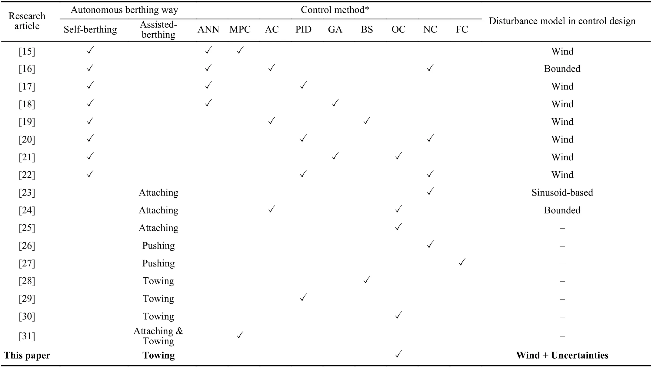
TABLE I CLASSIFICATION OF AUTONOMOUS SHIP BERTHING, CORRESPONDING CONTROL METHODS, AND DISTURbANCE CONSIDERATIONS
Assisted-berthing compensates the above limitation by transferring the high-demand control of one ship to the cooperative control of several autonomous tugs. In fact, this solution has gradually got attention since 2017 because some companies have launched projects to develop commercial autonomous vessels using tugboats [33]. According to their plans, tugboats will be one of the first vessel classes to become autonomous and the first step to “smart shipping”. It is worth highlighting that autonomous tugboats does not exclude the involvement of human operators. This depends on the levels of autonomy [34].
Assisted-berthing is a multi-agent over-actuated control problem. There is no preferable control method in this field,but the way of manipulation plays a key role, categorized as:attaching, pushing, and towing. Attaching is the way that a swarm of autonomous tugs is fixed around the ship in such a way that the position and orientation of each tug to the shipbody frame do not change. The number of tugs should be even, usually four [25] or six [23], [24], to guarantee the connected system has a force equilibrium in the vertical direction. Before attaching, the tugs approach the object forming a proper configuration to prevent the object from escaping (form closure). After the connection, they are regarded as thrusters offering power to the object. Hence, the original problem is transformed into a control allocation problem [35]. This is an effective way, but the collision avoidance between the tugs and the ship and the design of the attached device are key points that may limit the applicability[36]. Most of the research works following the attaching approach assume that the tugs are connected to the object, and ignore the two issues.
Pushing is the way to control the tugs by keeping in touch with the ship without the tugs being fixed to one point. The number of the tugs is determined by satisfying the“conditional closure” (a term used in robotics, meaning that robots push an object on one side only [37]). This way is often applied to cooperative manipulation problems by mobile robots (box-pushing problems) because the direction and magnitude of the forces offered by robots do not require to be strictly controlled and the conditional closure increases the degree of freedom of the manipulation system [38]. This is a simple and direct way, but the application scenarios are limited to static environment. The disturbances of the sea environment (mainly the waves and current) increase the danger of the pushing process. Only a few research works propose this manipulation way [26], [27].
Towing is the way to manipulate the ship by using towlines that connect the ship and the tugs. The minimum number of tugs is two. Towing manipulation is widely used for ship assisting berthing in maritime practice, because it is well adapted not only in harsh weather and sea conditions but also in some restricted waters, like congested canals, narrow bridges and dry-docks [39]. Compared to attaching, the tug has no contact with the ship, minimizing the risk of collision during the connection process, and there is no need for additional devices besides the towing equipment that exists in every ship or platform like winches, hooks, bollards and towlines. Compared to pushing, it ensures a safe distance between the ASV and the ship, increasing the robustness to the dynamic sea condition and extreme weather disturbances.In the related research works [28]–[30], the authors pay attention to manipulate a ship or an unpowered facility following a predefined path (position control). However, for the ship berthing problem, guaranteeing the safety and efficiency of the manipulation process requires the additional control of the heading and velocity.
From the view of disturbance consideration, research works on self-berthing mainly take into account wind disturbances[15], [17]–[22]. Studies on assisted berthing have limited numbers, just some papers of using attaching manipulation way utilize functions to approximate the sea conditions, like sinusoid-based [23] and bounded functions [24].
B. Contributions
This paper focuses on cooperative control of multiple autonomous tugs for ship towing under environmental disturbances. A multi-layer multi-agent control architecture is proposed to solve the problem, where a control agent is designed for each tug and a supervisory controller is used to coordinate the control agents. The main contributions of this research work are:
1) The proposed control scheme is designed not only to transport the ship to a desired position but also to regulate its heading and speed. The multi-layer control architecture offers the flexibility in performing different control tasks to coordinate multiple autonomous tugs.
2) Derivation of the kinematic model of the physically interconnected ship-towing system links the higher layer and lower layer controller. The desired towing forces and angles calculated by the higher layer (supervisory) controller are utilized through this kinematic model to compute the desired trajectories of the tugs, providing the on-line tracking reference for the lower layer (tug) controllers.
3) Considering the main influence of the wind, an adaptive weight coefficient matrix is designed. The matrix is timevarying according to the current ship states so that it can adjust the proportion of the penalty between position errors and velocity errors applied in optimal control strategy. This property is useful to force the ship to the desired states(especially for heading) in (hard) wind disturbances.Moreover, by tuning the matrix, the velocity of the ship through the whole towing process can be increased reducing the time cost.
In this paper, scaled models are considered because models for these are available (details are seen in Section IV), without loss of generality. Preliminary results of this work obtained assuming no disturbances are presented in [40]. Compared to[40], the proposed control scheme is designed to cope with environmental disturbances. Extensive simulations have been carried out to show the robustness of the proposed method in scenarios with various environmental disturbances in a realistic framework.
C. Outline
This paper is organized as follows. In Section II, the problem is described and transformed into the mathematical model. The design of the multi-layer multi-agent control algorithm is given in Section III. The results of simulation experiments are provided in Section IV to demonstrate the effectiveness of the proposed algorithm applied to a ship towing system with small-scale vessels, followed by the analysis and explanation. Finally, the conclusions and future research directions are given in Section V.
II. PRObLEM STATEMENT
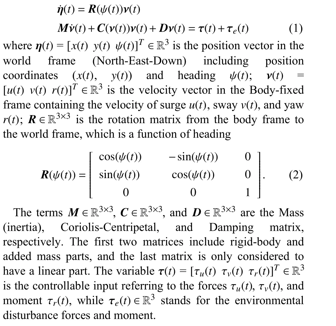
The plane motion of a vessel can be described by the 3-DOF(degree of freedom) kinematics and kinetics model, which is expressed as [41]
A. Controllable Input of the Vessels
In this work, we assume that the ship cannot move by itself.The power that moves the ship is offered by the forces through the towlines applied by the tugs. Thus, the controllable input of the ship τS(t) (in (1) τ(t)≜τS(t)) can be expressed as


Fig. 1. Physical schematic diagrams: (a) Ship; (b) Tug.
In order to meet the flexibility in ship assisted berthing, the actuator system of the tug generally contains two stern azimuth thrusters and one bow tunnel thruster (as shown in Fig. 1(b)), known as theASD tug[39]. With the help of three thrusters, the tug can obtain omnidirectional forces and moments. The controllable input τi(t)∈R3from the thrusters of tugican be expressed as

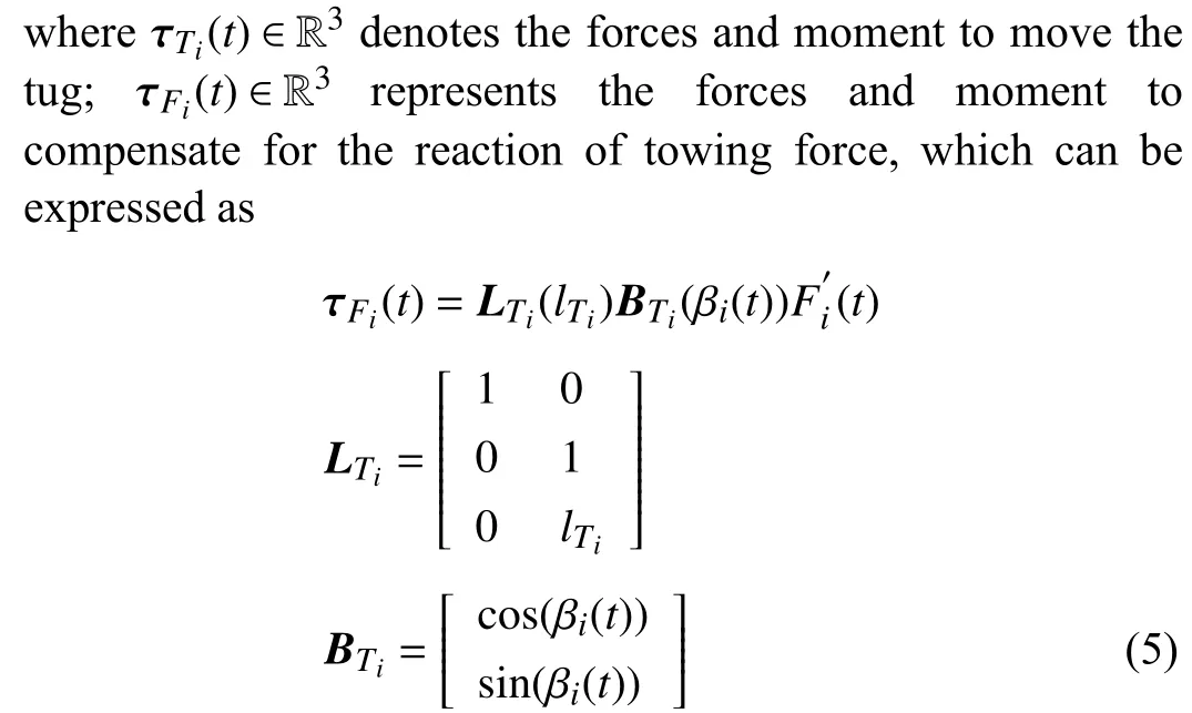

The interconnection between the ship system and the tug system is the towing forceFi(t). For the ship, the towing force provides power to move it, while for tugs, the towing force is the resistance effect which needs to be compensated.
B. Environmental Disturbances

The unknown part is difficult to be measured in real-time and characterized as stochastic, an approximated model will be illustrated in Section IV. On the contrary, the wind speed denoted byVw(t) and wind direction denoted by βw(t) can be easily measured by an anemometer and a weather vane in realtime, respectively. The effects of wind disturbances on a vessel (under velocityu(t),v(t), and heading ψ(t)), which are considered symmetrical with respect to thexzandyzplanes can be expressed by [41]


C. Towing System and Control Objective


Fig. 2. Typical towing system and control objective.
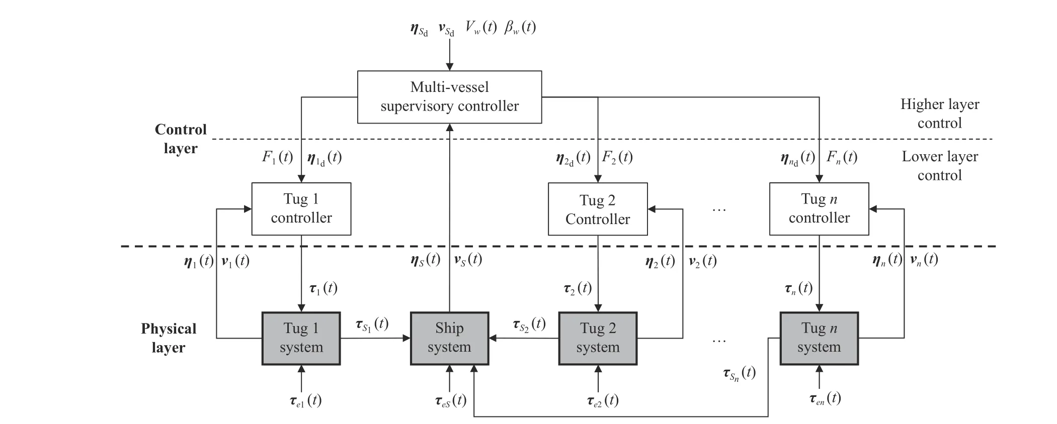
Fig. 3. Control diagram for the multi-vessel towing system.

III. MULTI-AGENT, MULTI-LAYER CONTROL SCHEME


A. Supervisory Controller
The inner structure of the supervisory controller is shown in Fig. 4. There are three core components: Optimizer, Adaptive Weight Calculator, and Reference Computation Unit.
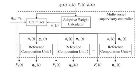
Fig. 4. Inner structure of the multi-vessel supervisory controller.
1) Optimizer:The objective of the optimizer is to compute the towing forces and angles. Due to multiple variables(towing forces and angles) that need to be determined, the optimal control method [44] is used to obtain a rational combination solving of these variables. Thus, the problem can be expressed as finding αi(t) andFi(t) to minimize the cost function

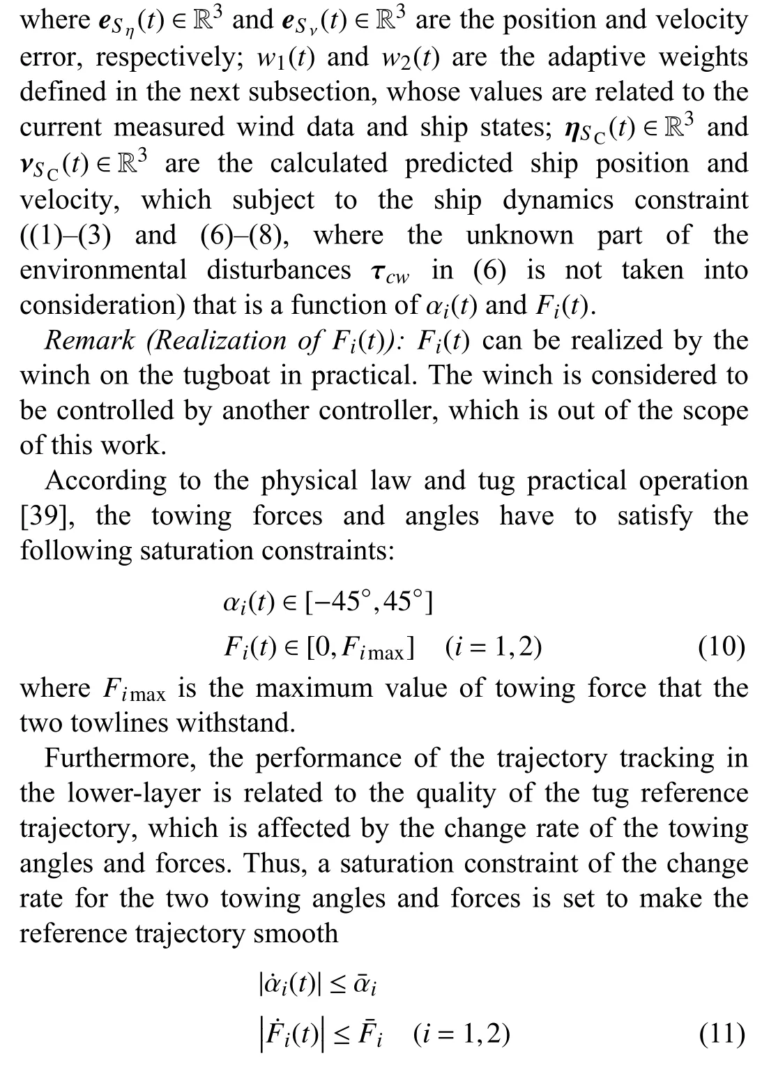


i)Requirement 1:Stable at the beginning
At the beginning of the towing, the task for the two autonomous tugs is to adjust themselves to a proper configuration to manipulate the ship. To stabilize the towing system, the velocity in this phase should be low with minimum fluctuation. Thus, the controller should focus on regulating the ship velocity.
ii)Requirement 2:Reach the goal in the end
At the end phase of the towing, as the towing system approaching the goal, the velocity asymptotically goes to zero.The task at this moment is to make sure the ship reaches the desired position with the desired heading. Thus, the controller should decrease the ship velocity and accelerate the regulation of ship position.
iii)Requirement 3:Robust to the wind
Due to the influence of the wind disturbances, it is difficult to stabilize the motion of the towing system at the beginning and the goal of the ship, especially the heading, is more difficult to achieve at the end phase. Thus, the controller should put more effort into satisfying the Requirements 1 and 2 according to the wind strength (Vw), and should prioritize the heading control.
iv)Requirement 4:Reduce control input oscillation
Control input oscillation determines the practicality of the proposed approach. A practical control approach should have less oscillation of the control input. Thus, at the end phase of the towing, the value of the weight should be designed as constant; in other phases, the changes in the weight should be smooth and not too much.
Based on the above requirements, the position weight is set asw1(t)=diag(1,1,1), while the adaptive velocity weightw2(t)=diag(wu(t),wv(t),wr(t))is designed as


Fig. 5. Geometrical kinematics of the ship towing system relation diagram: (a) General case; (b) Case in this paper.
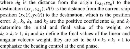
As the value ofd(t) decreases over the process of towing,the adaptive weightw2(t) is decreasing according to (12).When the ship is so close to the destination that the adaptive weight value is smaller than the terminal setting in (13), the adaptive weight will be fixed on the terminal value.
3) Reference Computation Unit:The Reference Computation Unit (see Fig. 3) aims to calculate the desired position and heading of the tug in order to tow the ship. The computation is realized based on the desired geometry relationship between the ship and tug. Once the towing forces and angles for the ship are provided by the higher layer control, the position and heading of the ship are determined. As shown in Fig. 5(a), the desired position and heading of tugican be calculated by the determined ship position and heading centre of gravity of the ship (G).


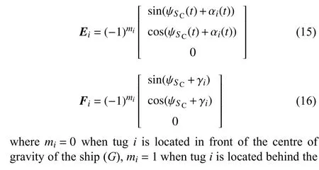
For the case in this paper, the geometrical kinematics of one ship and two tugs are shown in Fig. 5(b). It can be seen that γ1=0, γ2=0,m1=1,m2=0, so the correspondingE1,F1andE2,F2are
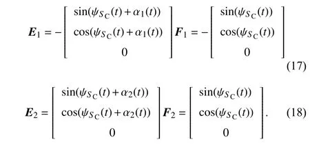
Thus, the algorithm flow in the higher layer control is summarized in Algorithm 1:
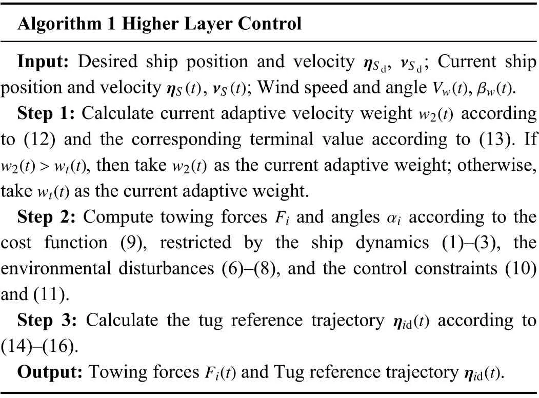
Algorithm 1 Higher Layer Control Input: Desired ship position and velocity , ; Current ship position and velocity , ; Wind speed and angle , .w2(t)ηS d νS d ηS(t) νS(t) Vw(t) βw(t)Step 1: Calculate current adaptive velocity weight according to (12) and the corresponding terminal value according to (13). If, then take as the current adaptive weight; otherwise,take as the current adaptive weight.Fi αi w2(t)>wt(t) w2(t)wt(t)Step 2: Compute towing forces and angles according to the cost function (9), restricted by the ship dynamics (1)–(3), the environmental disturbances (6)–(8), and the control constraints (10)and (11).ηid(t)Step 3: Calculate the tug reference trajectory according to(14)–(16).Fi(t) ηid(t)Output: Towing forces and Tug reference trajectory .

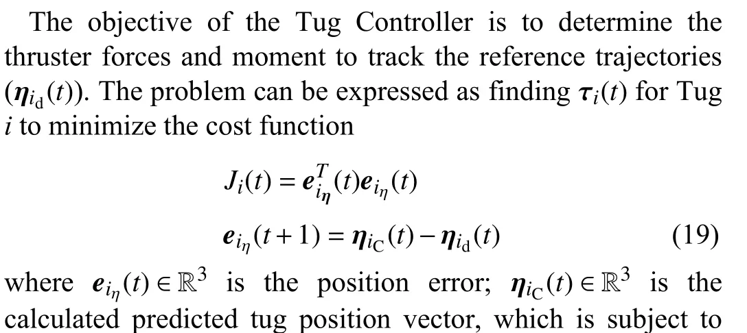


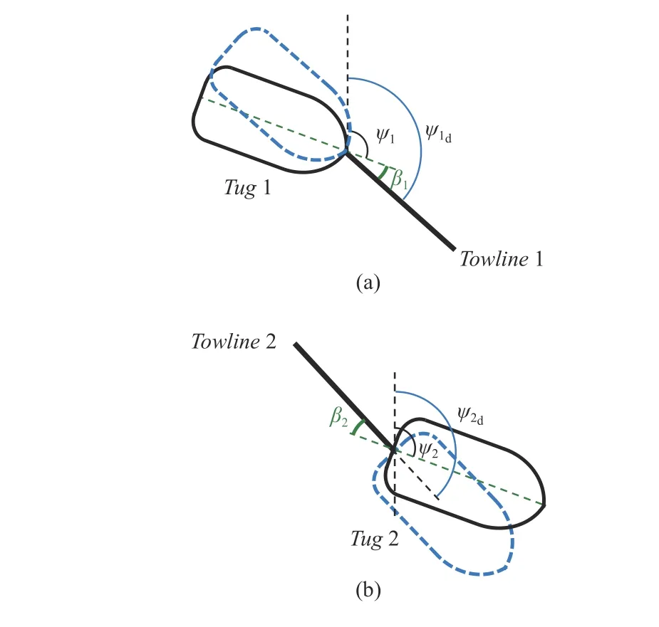
Fig. 6. Relationship among tug angle βi, desired tug heading ψ id and actual tug heading ψi: (a) Tug 1; (b) Tug 2.
The forces and moment of the thrusters satisfy the saturation constraints

where τimaxis the maximum value of the thruster forces and moment.
The main process steps of the lower layer control are summarized in Algorithm 2.
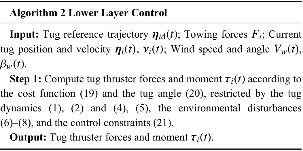
Algorithm 2 Lower Layer Control ηid(t) Fi ηi(t)νi(t) Vw(t)βw(t)Input: Tug reference trajectory ; Towing forces ; Current tug position and velocity , ; Wind speed and angle ,.τi(t)Step 1: Compute tug thruster forces and moment according to the cost function (19) and the tug angle (20), restricted by the tug dynamics (1), (2) and (4), (5), the environmental disturbances(6)–(8), and the control constraints (21).τi(t)Output: Tug thruster forces and moment .
IV. SIMULATION AND DISCUSSION
In this section, simulation results are presented to show the performance of the proposed control algorithm applied to scaled vessel models, followed by the discussion and analysis of theresults.The two tugs are modelled based on the “TitoNeri”, which is developed by TU Delft [45]. The ship model considered is the “CyberShip II”, which has been developed by NTNU [46].The design information for “TitoNeri” and “CyberShip II” is given in Table II, while the parameters and the physical constraints of the towing system are shown in Table III.
The environmental disturbances are simulated based on information provided by the port of Rotterdam [47].According to its latest meteorological information, 98% of the wind effects are not greater than 7 Beaufort (the wind speed is between 13.9 m/s and 17.1 m/s). According to Froude’s scaling law [48], the scaled velocity is determined by the square root of the scaling factor (k). Since the scaling factor of the “CyberShip II” is 70 [46], the scaled wind speed can be expressed as

The unknown disturbances (mainly refer to waves) are considered to have less effect than the wind. Since the trigonometric function can be used to approximate the spectrum of the waves, many ship motion control-related research works describe the unknown disturbances using sinusoidal function adding constant [49]–[52] or random parts(Asin(ω1t)+B×rand(t)) [53], [54]. However, for the environment near ports (windy but sheltered areas), the wave period is short [39] (Asin(ω2t)+B×rand(t) , ω2>ω1).Compared to the function image of a random function adding a constant (C×rand(t)+D), if the wave period is short enough, the two approximated ways are similar. In practice,the information of the wave height, period and length are difficult to be measured accurately and timely. In contrast,according to the above analysis, the simpler way can reflect both the short period wave character and randomness. Thus,the unknown disturbances can be described by a random function plus a constant.
From the meteorological point of view, waves and currents are generated by wind [55], which means their effects are related to the wind speedVw(t) and direction βw(t). Therefore,the unknown disturbances in this paper are expressed as

wherekX,kY, andkNare the unknown disturbance gain,whose values are less than 0.1; rand(t) is the random function from 0 to 1;aX,aY, andaNare the disturbance constant,whose values are less than 1;AFDandALDare the transverse and lateral projected area of vessel under the water,respectively; ψ is the vessel’s heading. In this simulation, the gains and constants are chosen askX=0.008,kY=0.01,kN=0.0016;aX=aY=aN=0.75.


TABLE II DESIGN INFORMATION OF “CYbERSHIP II” AND “TITONERI”

TABLE III PARAMETERS OF THE TOwING SYSTEM
A. Simulation Without Disturbances
When there are no disturbances, the ship towing process using the (A) and (B) control schemes are shown in Fig. 7.The two tugs cooperate to transport the ship to the goal position with the desired heading, but the time cost is different. In the first two sample times, the two control schemes have the same pace. At timet3=50 s, the Tug 2(blue) in Fig. 7(b) has already a horizontal displacement of 10 m, while it does not reach in Fig. 7(a). Aftert3, the average speed of the towing system controlled by scheme B is higher than scheme A, so the time cost by scheme B is less than scheme A. From the character of the system position under the nine sampled times, Fig. 7(a) shows the average distribution due to the constant velocity weight, while Fig. 7(b) is charactered dense in the beginning and end, sparse in the middle phase. This results from that the adaptive velocity weights (12) decrease as the towing system approaches the destination, the speed of the system increases. When the weights reach their terminal value they are constant, and the speed of the system decrease.

Fig. 7. Ship towing process without disturbances: (a) (A)-control scheme;(b) (B)-control scheme.
The states of the ship and two tugs are illustrated in Figs. 8 and 9, respectively. From Fig. 8, the velocities of the ship controlled by the two algorithms both converge to 0. The difference is that the peak value of the velocities using (B)-control scheme last a longer time, which makes the adaptive weights have a better time efficiency. From Fig. 9, the actual position and heading (solid line) of the two tugs match well with their online desired values (dashed line), which reveals that the tug controllers also accomplish their tasks well.
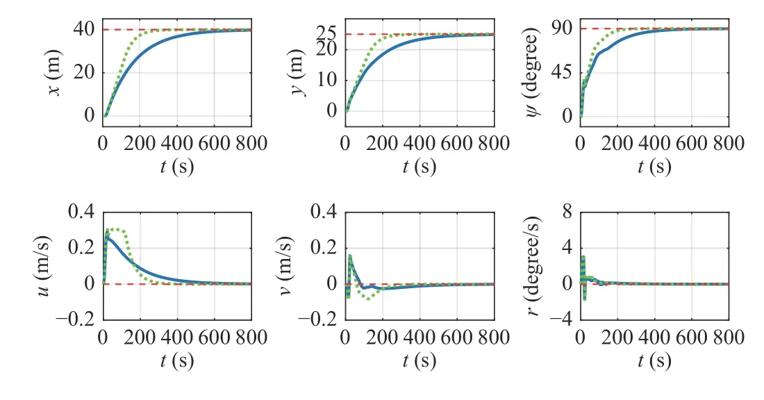
Fig. 8. Position, heading and velocities of the ship without disturbances using (A)-control scheme (solid, blue line) and (B)-control scheme (dotted,green line) algorithm; the dashed, red line represents the desired value.
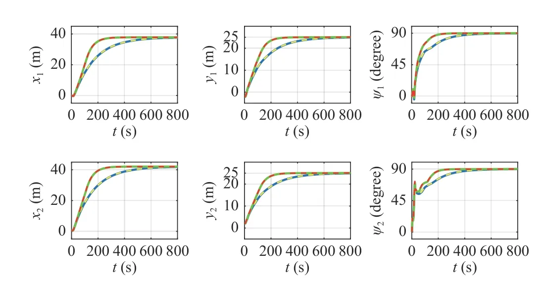
Fig. 9. Position and heading of Tug 1 (the first row) and Tug 2 (the second row) without disturbances: the solid blue line and dashed yellow line are the actual and desired values by using (A)-control scheme; the solid green line and dashed red line are the actual and desired values by using (B)-control scheme.
Fig. 10 shows the control input of the ship. Fig. 10(a)illustrates the two towing angles and two towing forces, which can be seen that the four values in both schemes are within the limitation (± 45°for towing angles and 3 N for towing forces).The change in towing forces using the (B)-control scheme is earlier than (A). Fig. 10(b) shows the change rate of the four control inputs, they are all within the maximum values(between the two red dashed line) as we set. Fig. 10(c) is the resultant forces and moment, whose values in both schemes converge to zero eventually.


Fig. 10. Control input of the ship without disturbances using (A)-control scheme (solid, blue line) and (B)-control scheme (dotted, green line)algorithm: (a) Towing angles and forces (red dashed line is the boundary); (b)Change rate of the angles and forces (red dashed line is the boundary); (c)Resultant forces and moment.

TABLE IV PERFORMANCE WITHOUT DISTURbANCES
B. Simulation With Disturbances
The wind speed in this simulation isVw=1 m/s, the direction is βw=45 degrees coming from southwest. The towing process of the two algorithms are shown in Fig. 11.Compared to the (A)-control scheme, the (B)-control scheme shows better robustness. Due to the disturbances, the (A)-control scheme makes the towing system steer toward the direction of environmental effects (the combined direction of the wind and unknown effects). In this configuration, the environmental forces affecting three vessels are the minimum(the force areas above and under the waters are minimum). So the system keeps this configuration to the end. The heading of the ship is finally around 55 degrees (see the evolution of ψ in Fig. 12 blue line).
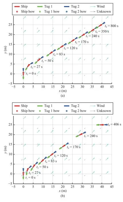
Fig. 11. Towing process of the two algorithms with disturbances: (a) (A)-control scheme; (b) (B)-control scheme.
Using the (B)-control scheme, the speed of the towing system is slower at the beginning to stabilize the ship against the wind effect. It can be observed that untilt7=240 s, the ship in Fig. 11(a) keeps ahead of that in Fig. 11(b). After that,as the adaptive weights keep reducing, the system speed is increasing. Att8=406 s, the ship in Fig. 11(b) achieved the goal. Under the disturbances, Fig. 11(a) still shows the average position distribution, while Fig. 11(b) is characterized as dense in the beginning and sparse in the end phase. In the simulation without disturbance (Fig. 7(b)), the values of the adaptive weights are changed from [150 150 150]Tto[50 50 50]T, which makes the velocity control focus on the beginning and end phase. In the simulation with disturbance(Fig. 11(b)), the values of the adaptive weights are changed from [300 300 300]Tto [6.5 6.5 0.5]T, which means that the velocity control is more concerned in the beginning phase,while the position and heading (especially the heading)control is emphasized in the end phase.
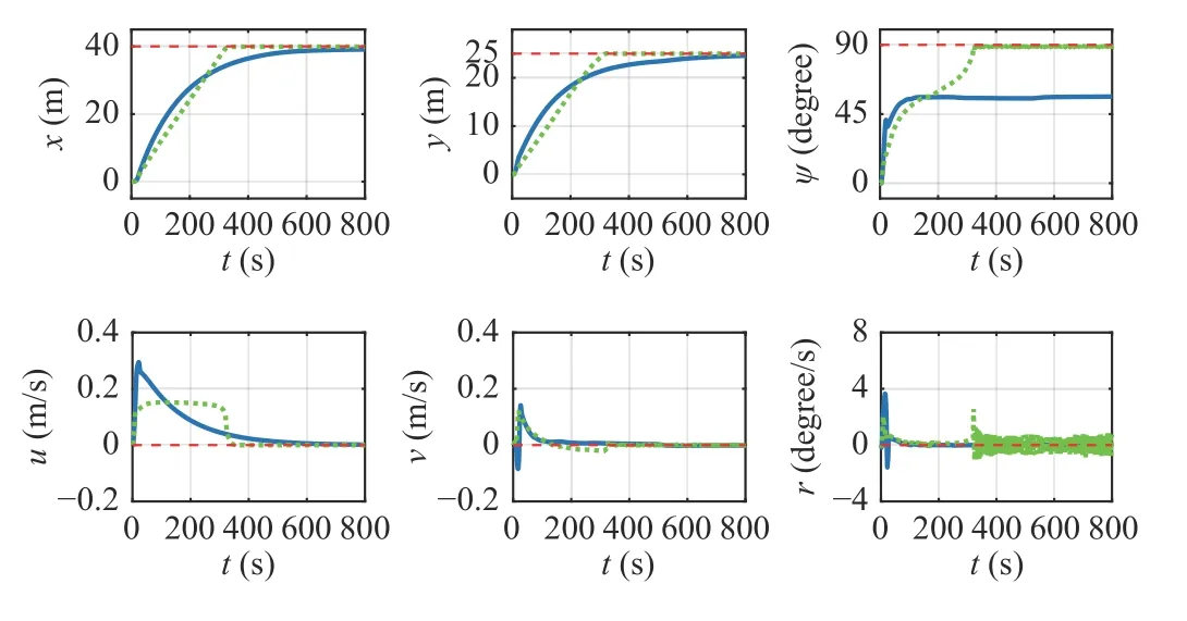
Fig. 12. Position, heading and velocities of the ship with disturbances using(A)-control scheme (solid, blue line) and (B)-control scheme (dotted, green line) algorithm; the dashed, red line represents the desired value.
Fig. 12 shows that by using the (B)-control scheme, the position and heading of the ship can reach their desired values and the linear velocities (uandv) converge to 0. The value of angular velocity (r) has a jump at about 320 s and then starts to fluctuate. The reason for such a change is that around 320 s,the position of the ship had already reached the desired value but not for its heading. At this moment, the controller put more effort into the heading control to make the ship have a large angular velocity. After achieving the desired heading,the wind and other disturbances still exist. In this condition,however, the desired heading is not a balanced state (the balanced state should be the heading in the end phase of the(A)-control scheme, around 55 degrees). Thus, the towing system has to continuously adjust to make the ship maintain its desired heading. Fig. 13 shows that the actual position and heading of the two tugs match well with their online desired values.

Fig. 13. Position and heading of Tug 1 (the first row) and Tug 2 (the second row) with disturbances: the solid blue line and dashed yellow line are the actual and desired values by using (A)-control scheme; the dotted green line and dashed red line are the actual and desired values by using (B)-control scheme.
The figure of control inputs (Fig. 14(a)) shows that the changes of towing angle are similar in both control scheme,the values of towing forces in the (B)-control scheme is greater than the (A)-control scheme, which reflects that the(B)-control scheme makes more effort to cope with the environmental disturbances. Despite this, the four control inputs in the (B)-control scheme are within the limitation (the green dotted line in Figs. 14(a) and 14(b) are all within the red dashed line). The value of the resultant forces and moment in Fig. 14(c), especially the and yaw moment, are not exactly zero in the end. The reason is the same as mentioned to the ship angular velocity that the ship has to compensate for the environmental effects to maintain the desired states, especially for the heading.

Fig. 14. Control input of the ship with disturbances using (A)-control scheme (solid, blue line) and (B)-control scheme (dotted, green line)algorithm: (a) Towing angles and forces (red dashed line is the boundary); (b)Change rate of the angles and forces (red dashed line is the boundary); (c)Resultant forces and moment.
The performance of the two control schemes in the case of simulated disturbances is shown in Table V. In this case, all the performance indexes in the (B)-control scheme outperforms than (A)-control scheme, especially for the heading control and time cost.

TABLE V PERFORMANCE WITH DISTURbANCES
C. Simulations in Harsh Conditions
In this part, two sets of simulations are carried out to show the performance of the proposed control scheme (B) under harsh conditions.
In the first simulation, wind speed is set to be varying. As shown in Fig. 15, the first row is the wind speed varying from 1 m/s to 2 m/s. The second and third-row shows the real-time ship states, which indicates that under the condition of varying wind speed, the control scheme (B) can make sure that the ship achieves its desired position and heading. The performance indexes: position errorep=0.21%, heading erroreψ=1.65%, time costt=472 s.

Fig. 15. Position, heading, and velocities of the ship (the second and thirdrow) under the varying wind speed (the first row) disturbances using (B)-control scheme algorithm.
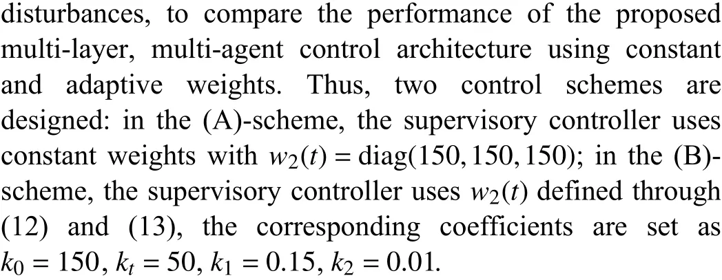
In the second simulation, wind speed is set to be the maximum value (2 m/s) at all time. The performance of the(B)-control scheme with different wind directions is shown in Table VI.
When the wind direction is 0°or 180°, the position and heading control shows the best performance. Since the goal heading is vertical to the wind direction, the two tugs form the arching ( 0°) or sagging (1 80°) configuration to make the ship against the lateral forces, and this manipulation costs more time.
When the wind direction is 90°or 270°, the values of position and heading error are slightly higher, but the timecost is the minimum. This is because the goal heading is parallel to the wind direction, and the force area is minimum.The two tugs only have to maintain the ship velocity being zero at the goal position.

TABLE VI PERFORMANCE OF THE (B)-CONTROL SCHEME WITH SIMULATOR WIND SPEED 2 M/S
When the wind direction is 30°or 45°or 60°, it is more difficult to achieve the desired position and heading(especially the heading). The disturbance effects, on one hand,force the ship to move; on the other hand, they make the ship difficult to achieve the goal heading. So it is hard to keep the ship steady (velocity zero) and turn the ship heading to the goal direction. Despite the above difficulties, the results show that both position and heading goals are achieved within tolerance.
Based on the above simulation results, the proposed control method shows the following abilities. First, it can coordinate the two autonomous tugs to cooperatively manipulate a ship to the desired position with the desired heading. Second, it can deal with the environmental disturbances (mainly wind) even in harsh conditions. Third, it properly adjusts the ship speed according to the current ship states making the towing process time-efficient. In a real situation, once we obtain the information of the real-scaled vessel model, the proposed control method can be used to coordinate the autonomous tugs to manipulate a ship to the desired position with the desired heading under the environmental disturbances.
V. CONCLUSIONS AND FUTURE RESEARCH
This paper focuses on the cooperative control of multiple autonomous tugs for ship towing under the environmental disturbances. We propose a multi-layer multi-agent control scheme to manipulate a ship to reach a desired position with desired heading and velocity. The control scheme consists of a supervisory controller in the higher layer and two tug controllers in the lower layer.
The supervisory controller computes the desired towing forces and angles by minimizing the cost function of position and velocity errors. The weight coefficients of the position and velocity in the cost function determine the performance of control. To guarantee that the towing system functions well under environmental disturbances, an adaptive weight function is designed. By applying this weight, the controller shows disturbance robustness, time efficiency and tracking performance.
The calculated towing angles by the supervisory controller are used to compute the online reference trajectories for the autonomous tugs based on the kinematics of the ship towing system. The tug controller, on one hand, provides the towing forces to move the ship; on the other hand, it tracks the reference trajectory to reach the configuration determined by the towing angle.
Simulation experiments illustrate the performance of the proposed control scheme. When there are no disturbances, the proposed method shows more efficiency. When the motion of the towing system is affected by the wind (mainly) and unknown disturbances, the proposed method shows robustness guaranteeing that the ship is manipulated to a desired position with desired heading and velocity, even in harsh conditions.
Future research will focus on collision avoidance of the towing system. In this paper, only the meteorological environment is concerned. However, the navigation environment also has many effects on the ship manipulation.The congested waterways in port areas increases the challenges for the towing process. Thus, an efficient collision avoidance strategy is the key to ensure the safety of the ship.
杂志排行
IEEE/CAA Journal of Automatica Sinica的其它文章
- Distributed Subgradient Algorithm for Multi-Agent Optimization With Dynamic Stepsize
- Kernel Generalization of Multi-Rate Probabilistic Principal Component Analysis for Fault Detection in Nonlinear Process
- Learning Convex Optimization Models
- An RGB-D Camera Based Visual Positioning System for Assistive Navigation by a Robotic Navigation Aid
- Robust Controller Synthesis and Analysis in Inverter-Dominant Droop-Controlled Islanded Microgrids
- Passivity-Based Robust Control Against Quantified False Data Injection Attacks in Cyber-Physical Systems
