Enhanced removal of ultrafine particles from kerosene combustion using a dielectric barrier discharge reactor packed with porous alumina balls
2021-07-07JingLI李晶HaiquanLU陆海全QiWANG汪琦GuojianLI李国建ShuiliangYAO姚水良andZuliangWU吴祖良
Jing LI(李晶),Haiquan LU(陆海全),Qi WANG(汪琦),Guojian LI(李国建),Shuiliang YAO(姚水良)and Zuliang WU(吴祖良)
1 School of Environmental and Safety Engineering,Advanced Plasma-Catalysis Engineering Laboratory for China Petrochemical Industry,Changzhou University,Changzhou 213164,People’s Republic of China
2 Engineering Research Center of Construction Technology of Precast Concrete of Zhejiang Province,Hangzhou 310018,People’s Republic of China
3 Anji Runfeng Air Purification Technology Co.Ltd.,Hangzhou 313300,People’s Republic of China
4 Zhejiang Gongshang University,Hangzhou 310018,People’s Republic of China
Abstract Ultrafine particles(UFPs)are harmful to human beings,and their effective removal from the environment is an urgent necessity.In this study,a dielectric barrier discharge(DBD)reactor packed with porous alumina(PA)balls driven by a pulse power supply was developed to remove the UFPs(ranging from 20 to 100 nm)from the exhaust gases of kerosene combustion.Five types of DBD reactors were established to evaluate the effect of plasma catalysis on the removal efficiency of UFPs.The influences of gas flow rate,peak voltage and pulse frequency of different reactors on UFPs removal were investigated.It was found that a high total UFP removal of 91.4% can be achieved in the DBD reactor entirely packed with PA balls.The results can be attributed to the enhanced charge effect of the UFPs with PA balls in the discharge space.The UFP removals by diffusion deposition and electrostatic attraction were further calculated,indicating that particle charging is vital to achieve high removal efficiency for UFPs.
Keywords:ultrafine particles,dielectric barrier discharge,porous alumina balls,charge effect,removal efficiency
1.Introduction
Inhalable particulate matter(PM)that can stay in the air for long periods of time has a great impact on human health[1,2].According to the range of aerodynamic equivalent diameter(AED),PM can be termed as total suspended particulates(AED of less than 100 μm),PM10(AED of less than 10 μm),PM2.5(AED of less than 2.5 μm),and ultrafine particles(UFPs,AED of less than 100 nm)[3–5].The primary components of UFPs are organic matters and inorganic carbons,which come from the combustion of fuels,such as automobile exhaust and industrial processes[6,7].Normally,the UFPs are neither considered nor stipulated in the emission regulations due to their low mass contribution[8–10].Nonetheless,UFPs can penetrate through different systems of the body,such as the brain,respiratory,and cardiovascular systems.Evidence suggests that UFPs are more harmful to the respiratory system than micro-sized particles[11,12].Thus,many treatment technologies have been developed to reduce UFP emissions.
Among these technologies,filtration has been recognized as an efficient removal technology[13–18].However,the UFPs removal efficiencies are depended on the size distribution of the UFPs[19,20].Electrostatic precipitators(ESPs)have also been successfully used in industry to collect the particles from exhaust gases,such as in coal power generation[21–23].The total PM removal efficiency by using ESP technology was above 95%based on mass.However,the total removal efficiency of UFPs was decreased to 80%based on number concentrations[24–26].Therefore,a complementary technology should be implemented to enhance the removal efficiency of particles at nanoscale sizes.For example,a self-cleaning/maintenance-free aerosol filter with nonthermal plasma(NTP)was utilized to remove UFPs at atmospheric pressure.The efficiencies were enhanced to 48%at 20 nm and 90% at 100 nm[27].In addition,a soft x-ray charger was used prior to the exhaust gases flowing into the ESP[28].The collection efficiencies were improved to 58%at 20 nm and 92% at 100 nm due to the enhanced particle charging,whereas the efficiencies were respectively only 12%and 50% at 20 and 100 nm without charging.
Recently,NTP-catalysis technology has been successfully applied to reduce the production of PM in the field of volatile organic chemical decomposition[29–37],which has been anticipated to be one of the alternative techniques for UFP removal.Meanwhile,it has been found that particles in the range of 20–100 nm are rarely produced in the decomposition processes of benzene using a dielectric barrier discharge(DBD)reactor with CeO2/γ-Al2O3catalysts[38–40].However,there is scarce research on UFP removal using a DBD reactor packed with porous dielectric balls.
In this study,the removal of UFPs from the exhaust gases of kerosene combustion in a DBD reactor packed with porous alumina(PA)balls was investigated.The influences of PA balls,reactor types,voltage values,frequencies of voltage pulse and gas flow rate on UFP removal were systematically evaluated.Furthermore,a modified model for UFP removal in the DBD reactor packed with PA balls was simulated based on the experimental results.
2.Experimental and data analysis
2.1.Experimental set-up
The experiments for the UFP removal were conducted by using the set-up shown in figure 1.The air was supplied by using an air pump with a polytetrafluoroethylene-sintered filter(15×10×51 mm3,Suzhou Mingrui,China),which can remove nanoparticles from 10 to 350 nm,with a filtration efficiency greater than 99.4%[41].Three air flow meters(FM1-3,LZB-3WB,Changzhou Xinwang,China)were used.FM1 was used to control the air with a fixed flow rate of 2 l min−1to a quartz tube(50×45×800 mm3)in which a kerosene lamp was installed.The kerosene lamp was used to generate the UFPs from kerosene(Zippo,USA)combustion.The gas from the kerosene lamp was dehydrated using an ice bath.FM2 was used to dilute the gases from the quartz tube with the air into the gas mixer.The gas mixtures were supplied to the DBD reactor.As shown in figure 2,five types of DBD reactors were used.All of the DBD reactors generally consisted of a stainless steel frame,two alumina plate blocks,two alumina plates(purity 96%,115×115×1 mm3),two stainless steel electrodes(95×95×0.3 mm3or 48×95×0.3 mm3),two organic glass spacers(115×10×5 mm3),and two organic glass holders(115×10×2 mm3).The organic glass spacers were used to keep a space distance of 5 mm between the two alumina plates and to allow all of the gas mixtures to pass the space between two alumina plates.PA balls(purity 95% Al2O3,Zibo Jianlong,China)were placed in the space.The diameters of the PA balls were around 5 mm,with a number of about 19×19 balls in total in Reactor B.In Reactors C and D,PA balls were placed downstream and upstream of the discharge regions,respectively.The PA balls had a Brunauer–Emmett–Teller(BET)surface area of 384 m2g−1,an average pore size of 4.31 nm and a pore volume of 0.413 cm3g−1.These were measured by using a N2adsorption apparatus(Micromeritics JW-BK 132F,Beijing JWGB,China).The packing density was around 0.722 g ml−1.
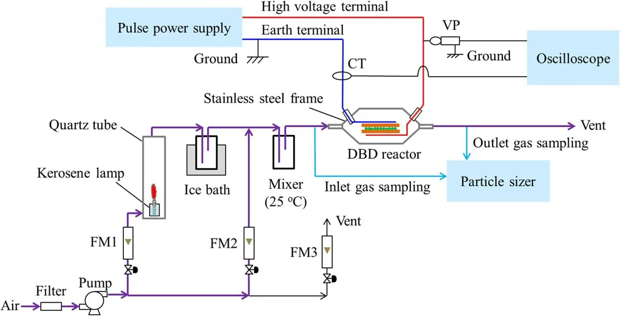
Figure 1.Experimental set-up for nanoparticle generation and cleaning.
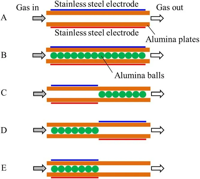
Figure 2.Geometries of the different configurations of DBD reactors.
A pulse power supply(DP-12K5-SCR,PECC,Japan)was used to supply pulsed voltage to the stainless steel electrode terminals of the DBD reactor.The pulsed discharges were generated within the discharge space between the two alumina plates covered with the two stainless steel electrodes.The waveforms of discharge voltage and current were measured by using a voltage probe(VP,P6015A,Tektronix,USA),a current transformer(CT,TCP 0030,Tektronix,USA)and a digital phosphor oscilloscope(DPO 3034,Tektronix,USA).
The particle number concentrations in the gases at the inlet and outlet of the DBD reactor were detected by using a scanning mobility particle sizer(SMPS+E,Grimm,Germany)equipped with a differential mobility analyzer in an aerodynamic diameter ranging from 6.25 to 1093.95 nm.In addition,a condensation particle counter that can measure particles in a number concentration range of 0–107cm−3(the number of particles per cubic centimeter)was simultaneously utilized.
2.2.Data analysis
The energy injection,P,in J Hz−1from the pulse power supply to the DBD reactor was calculated using equation(1):
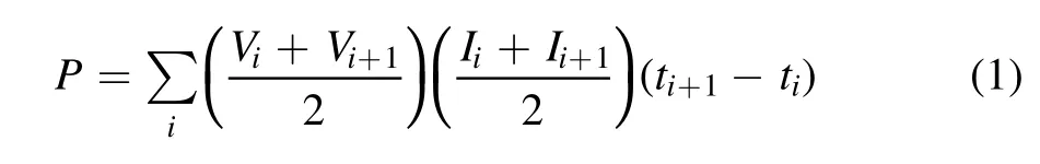
whereViandVi+1in V were the discharge voltage at the discharge timestiandti+1in s;andIiandIi+1in A were the discharge current attiandti+1,respectively.VandIwere obtained from the data sequences of the discharge voltage and current waveforms,iranged from 0 to 9999,andfwas the pulse frequency in Hz.
The total UFP removalXtwas defined as equation(2).The sized UFP removal for a fixed diameterxjwas calculated by using equation(3),wherenjandNjwere the particle number concentrations in cm−3in the outlet and inlet gases of the DBD reactor,respectively,andjwas an index for the particle of an aerodynamic diameterdiranging from 20 to 100 nm.

The mechanism of UFP removal by PA balls generally includes inertial collision,direct interception,diffusion deposition,gravity settlement and electrostatic attraction.As the diameters of the UFPs considered in this work were between 20 and 100 nm,the inertial collision,direct interception and gravity settlement were neglected,and only diffusion deposition and electrostatic attraction were thought to be the mechanism of UFP removal by PA balls.
The carbon balance(CB)was calculated by using equation(4):

where∑Sinand∑Soutwere the sums of mass of all the particles at a range of 20–100 nm from the exhaust gases of kerosene combustion at the inlet and outlet of the DBD reactor,respectively.
The efficiency of a single PA ball due to diffusion deposition was given by the Péclet number(Pe)as[42]:
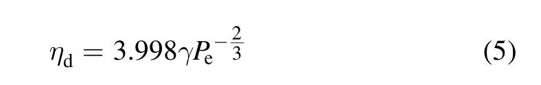
where γ was the laminar hydrodynamic factor,and given by equation(5)[43],and calculated using the porosity of the PA balls(ε,0.62).Pewas obtained using equation(6).
U0was the face velocity in m s−1;dBwas the mean diameter of the PA balls in m;andDwas the particle diffusion coefficient in m2s−1given by:

in whichkwas the Boltzmann constant(1.38×10⁻²³J K−1),Twas the gas temperature(298 K),andμgwas the air dynamic viscosity(1.84×10⁻⁵Pa s).Cuwas the Cunningham coefficient given by:
λgwas the mean path of an air molecule(66 nm at 25°C and atmospheric pressure).a=1.165,b=0.483,andc=0.997 were obtained from Kimet al[44].
The electrostatic attraction by a single PA ball was evaluated using equation(9):
γswas the collector polarization coefficient.KEwas the dimensionless parameter of the Coulombic force[45,46].
The total collection efficiencyηiby a single PA ball was then calculated using
The total collection efficiencyηtby 19 PA balls in the gas stream was then calculated using

3.Results and discussion
3.1.Discharge characterizations
The typical waveforms of discharge voltage and current for five types of DBD reactors filled with or without PA balls were shown in figure 3,where the peak voltages of each voltage pulse for five types of the DBD reactors were set at approximately 9.0 kV.Each voltage waveform had positive and negative pulses.As shown in table 1,the rise time(tr)and full-width at half-maximum of the voltage pulse(tw)were 3.3–4.4 and 19.0–20.8 μs,respectively.The peak discharge currents and energy injection were in the order of Reactor B>Reactor E>Reactor A>Reactors C and D.

Figure 3.Typical waveforms of the discharge voltages and currents.
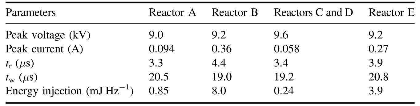
Table 1.Discharge performance of each reactor.
To understand the differences between discharge performances in the five types of DBD reactors,the relationship of energy injection as a function of peak voltage was investigated(figure 4).The energy injection gently increased when the peak voltage increased to a peak voltage of less than 5.0 kV,and greatly rose when the peak voltage was higher than 5.0 kV.The value of 5.0 kV was the inception voltage(Vin)for the pulsed corona discharges that occurred within the gas space between two alumina plates.However,when packing the PA balls in the discharge space(Reactors B and E),the energy injection was greater than those without PA balls(Reactors A,C and D).This was because when the PA balls were in the discharge space,the pulse voltage across the dielectric balls was lower than that across the gases of the same space without dielectric balls(as the relative permittivity of the dielectric balls was higher than that of the gases)[38].This resulted in an increase in the pulse voltage across the reduced gas space.Thus,the energy injection into the reduced space in the DBD reactor packed with PA balls was higher than that into the DBD reactor without dielectric balls.
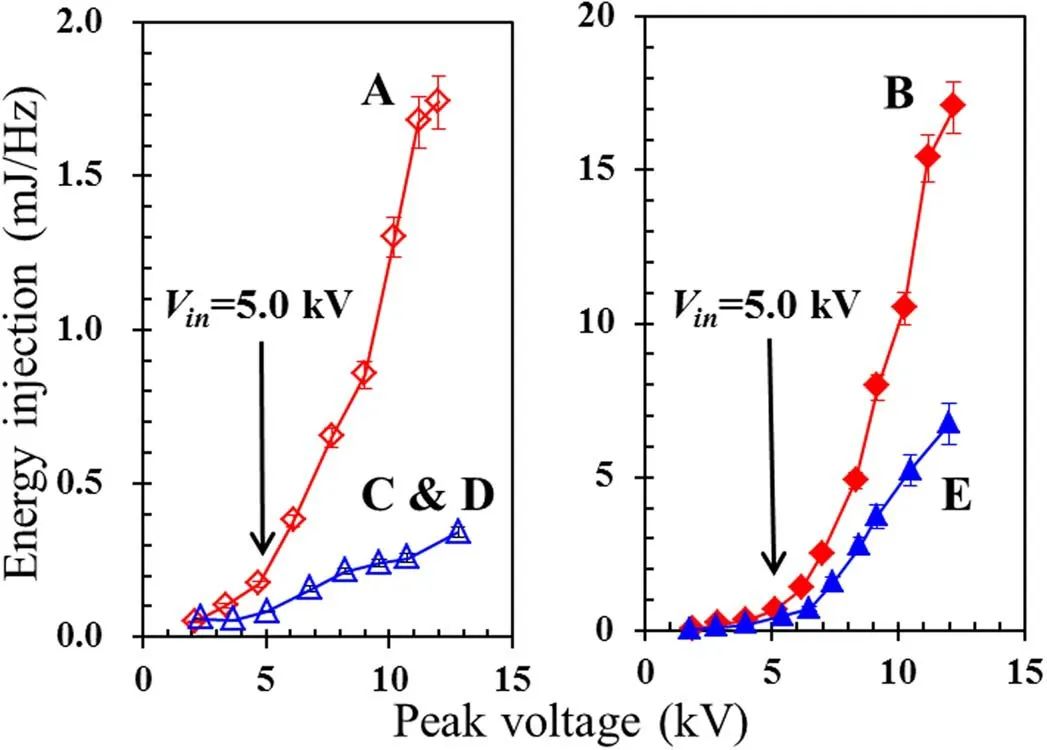
Figure 4.Energy injection as a function of peak voltage for each reactor.
3.2.Effect of PA balls on UFP removal
The UFP removal without PA balls was initially evaluated by using Reactor A.Figure 5(a)shows the UFP number concentrations in the inlet and outlet gases.The UFP concentrations in the inlet gases had a peak of 3.4×106cm−3at 48.3 nm in the range of 20–100 nm,while those in the outlet gases also had a peak of 3.2×106cm−3at 48.3 nm.The UFP removal efficiency was only at a level of 10% with a gas residence time in the discharge space of 1.38 s(figure 5(b)).The low UFP removal was due to the fact that the UFPs could be finitely adsorbed on the surfaces of alumina plates in the DBD reactor.
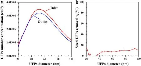
Figure 5.(a)UFP number concentrations in the inlet and outlet gases of reactor A;and(b)sized UFP removal under experimental conditions of 9 kV,50 Hz,and 2 l min−1.
The effect of PA balls on the UFPs removal was then investigated by using Reactor B(figure 6(a)).The UFPs number concentration in the gases at the inlet had a peak value of 4.73×106cm−3at 40.2 nm in the range of 20–100 nm.When there was no discharge,the UFPs number concentration in the outlet gases was decreased to 2.72×106cm−3at 40.2 nm.The sized UFPs removal was enhanced to 60% at 20 nm and decreased with increasing UFPs diameter(figure 6(b)).This was due to the UFPs adsorption on the PA balls.When pulse voltages were applied on to the DBD reactor,pulsed discharges occurred within the reactor,resulting in the obvious decreases of the UFPs number concentration.The peak value of the UFPs number concentration decreased to 6.65×105cm−3at 58.3 nm.The sized UFPs removal was around 90% in the range of 20–100 nm(figure 6(b)).It was indicated that the adsorption capacity of PA balls was enhanced during the discharges.
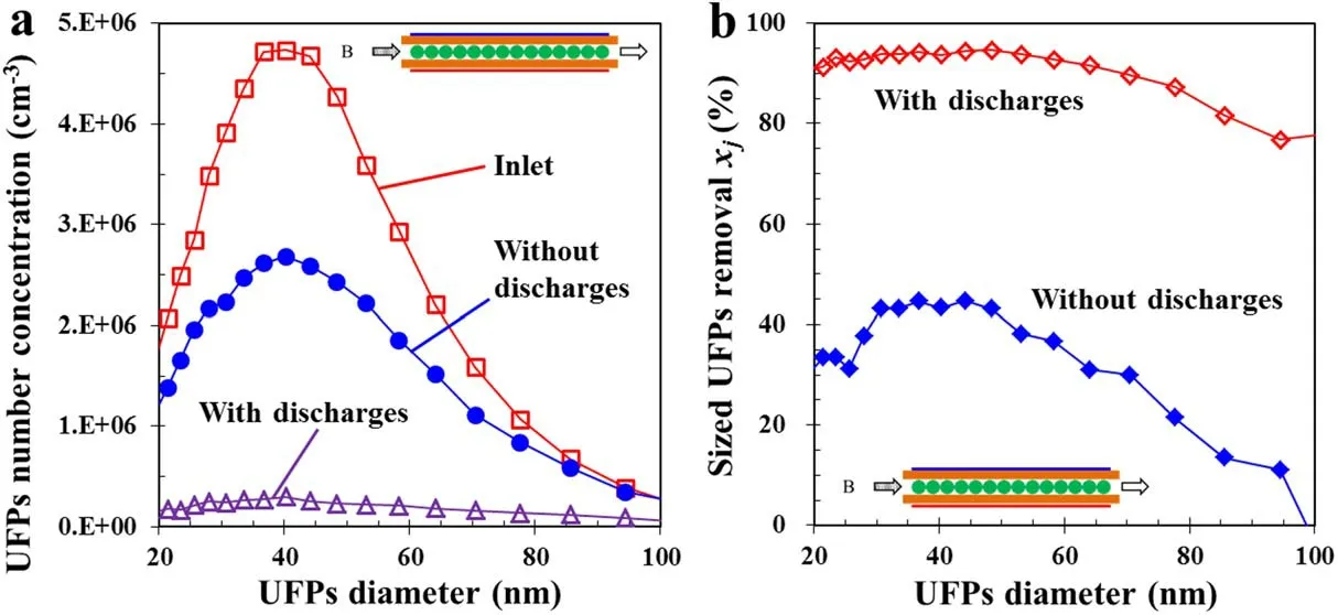
Figure 6.(a)UFPs number concentrations in the inlet and outlet gases of Reactor B,and(b)the corresponding sized UFP removal under the experimental conditions of 50 Hz,2 l min−1 and 9.2 kV.
3.3.Factors influencing total UFP removal
The relationships of the total UFP removal at various peak voltages were evaluated.When using Reactor A without PA balls(figure 7(a)),the total UFP removal increased with an increase in the peak voltage.The total UFP removal was 32% at a 12 kV peak voltage.When the PA balls were fixed in Reactor B(figure 7(b)),the total UFP removal was 35.9% at 0 kV,indicating that those parts of UFPs were removed due to the adsorption by PA balls.When the peak voltage was increased to 7–11 kV,at which corona discharges occurred within the discharge spaces,the total UFP removal was enhanced to approximately 90%.The total UFP removal using Reactor B at a peak voltage higher than 7 kV was obviously higher than that using Reactor A,which again indicated that PA balls play an important role in the UFP removal.The main reason was that the particles were charged and more facilely captured by the dielectric PA balls[47].
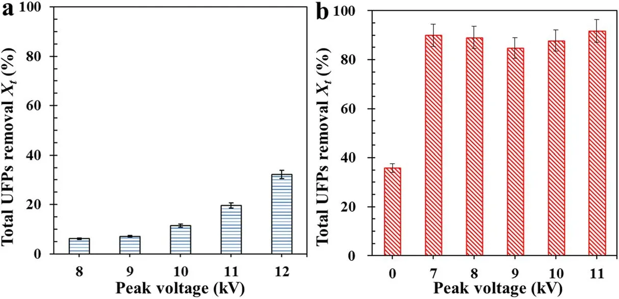
Figure 7.(a)Total UFP removal efficiency without PA balls by using Reactor A at various peak voltages;and(b)total UFP removal efficiency with PA balls by using Reactor B at various peak voltages.Reaction conditions:50 Hz pulse frequency with a 2 l min−1 gas flow rate.
Figure 8(a)shows the evaluation of different types of DBD reactors on the UFP removal.It was found that total UFP removal was only 7.1%using Reactor A under the experimental conditions of 9.0–9.6 kV,50 Hz and 2 l min−1gas flow rate.When packing the PA balls before the discharge space of Reactor D,the total UFP removal increased to approximately 35.0%due to the adsorption ability of the PA balls.Encouragingly,the total UFP removals improved to 84.1% and 85.6%,when using Reactors of C and E,respectively.The results indicated that total UFP removal is strongly affected by the location of PA balls in the DBD reactor.PA balls placed downstream of the discharge regions(Reactor C)were more efficient than those placed upstream of the discharge regions(Reactor D).The PA balls packed inside the discharge regions of Reactor E showed a relative improvement in UFP removal compared to the others.In Reactor B,91.4%of UFPs were removed when the DBD reactor was fully filled with PA balls and equipped with electrodes,which had double the amount of PA balls compared to Reactor E during discharges.This can be attributed to the enhanced effect on particle charging and the adsorption by the PA balls.
Figure 8(b)displays the removal efficiency of sized UFPs versus the particle diameters.The sized UFP removals for a fixed diameter in Reactors B,C and E were higher than those in Reactors A and D at the range of 20–100 nm.The sized UFP removal of 20–30 nm in Reactor B showed better efficiency than that in Reactor E.The particle removal of diameters from 20 to 70 nm in Reactor C was less efficient than those in Reactors B and E.The carbon balances of total UFP removal for the five types of DBD reactors were 7.6%,90.5%,87.8%,46.3% and 89.0%,respectively(figure 9).These values were proportional to the values of total UFP removal(figure 8(a)).The values of carbon balances for the five reactors were obviously different,mainly due to the differences in charge effect and the specific surface areas of the PA balls.The highest carbon balance value was found in Reactor B.Reactor E had half the amount of catalysts compared with Reactor B,and thus the carbon balance value was smaller than that in Reactor B.The charged UFPs in Reactor C were partly neutralized during the transfer processes.Therefore,the value of carbon balance was less than those in Reactors B and E.Moreover,the influences of pulse frequency and gas flow rate were analyzed.The total UFP removal was around 90%regardless of changes to the pulse frequency and gas flow rate(figure 10).
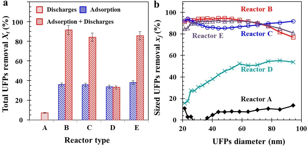
Figure 8.(a)Total UFP removals using different DBD reactors and(b)corresponding sized UFP removal versus UFP diameter under the experimental conditions of 9.0–9.6 kV,50 Hz and 2 l min−1 gas flow rate.
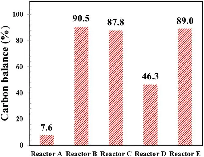
Figure 9.Carbon balance as a function of five types of DBD reactors.
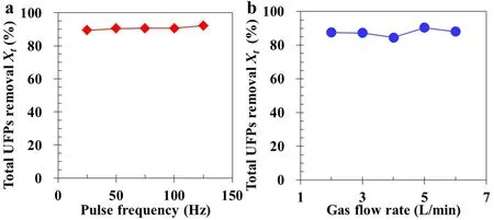
Figure 10.Total UFP removal at different(a)pulse frequencies and(b)gas flow rates under the experimental conditions of(a)9.0 kV and 2l min−1,and(b)9.0 kV and 50 Hz.
3.4.Mechanism of UFP removal
To clarify the mechanism of UFP removal using the DBD reactor packed with PA balls,the experimental results using Reactors B and C were compared to illustrate the effects of particle charging and PA ball adsorption.The discharge space was upstream of the PA balls in Reactor C(figure 2),and the particles in the gas stream were charged when passing through the discharge space.The total UFP removal was 84.1%,an approximately 8% decrease in comparison with that using Reactor B.This was due to the fact that the charged particles were immediately collected by the PA balls via the electrostatic force in Reactor B.However,parts of the charged particles were neutralized in Reactor C before crossing through the space packed with PA balls.Thus,fewer UFPs were adsorbed by the PA balls downstream of the DBD reactor.
In this work,a DBD reactor was utilized to remove UFPs from kerosene combustion.UFPs were positively or negatively charged by plasma discharges.These charged particles were facilely adsorbed by PA balls due to the electrostatic force.However,the total UFP removal did not approach 100%,due to the charging efficiency being unable to reach 100%.Fine particles,with diameter smaller than 100 nm,are mainly charged by the diffusion of ions to the surface of the particles.The final number of charges per particle depends on the particle size and on the charging conditions.With the short transit time in the DBD reactor,UFPs(diameter<60 nm)were not completely filtered by electro-collection due to the small fraction of charged particles[27].For example,the charged fraction was less than 60%for particles between 5–35 nm in the corona charger[48].
Meanwhile,according to the calculation equations in section 2.2,the removal efficiency of UFPs was related to the particle size regardless of the modes of diffusion deposition or electrostatic attraction.The effect of the electrostatic forces on UFP removal was calculated using equation(11).Figure 11 shows theKEvalues while gas flow rate,pulse voltage or pulse frequency were changed.It was found that theKEvalues varied with particle size and generally had a peak at a diameter around 40 nm,and had an order of about 0.05 under different conditions,close to that given by Shapiroet al[46].
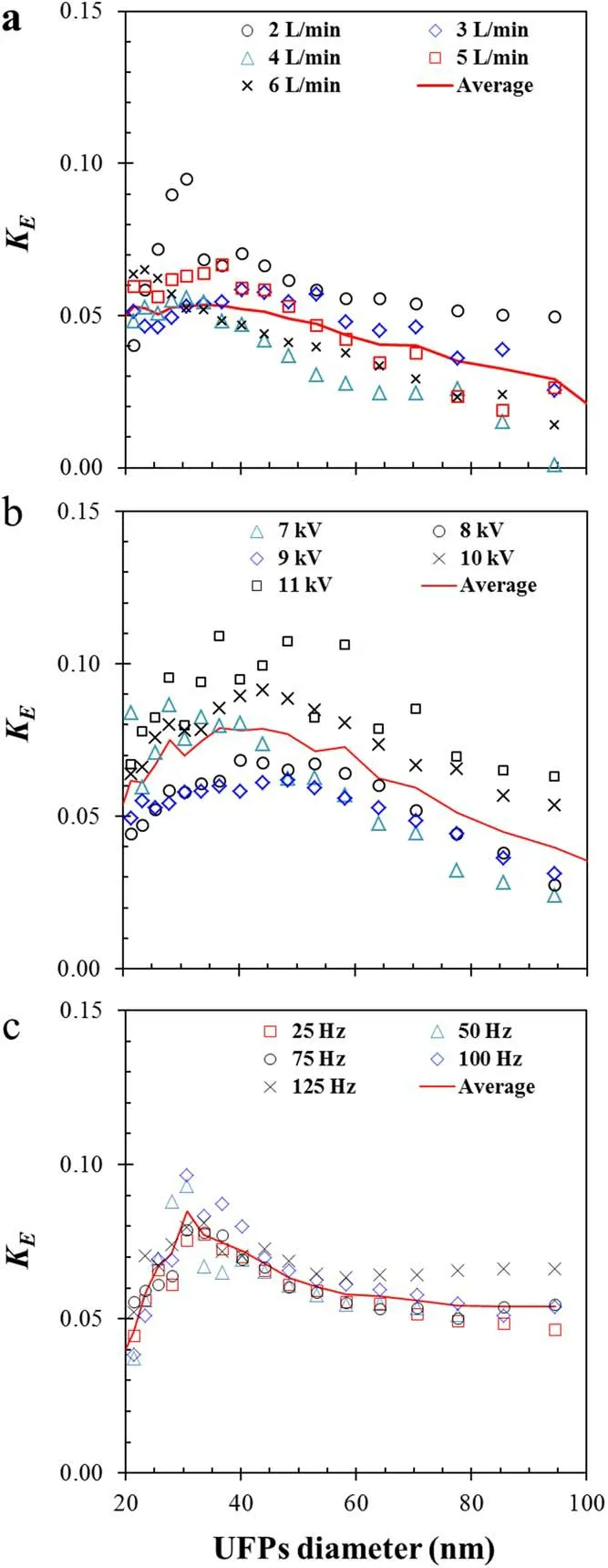
Figure 11.KE values of a single PA ball in Reactor B as a function of UFP diameter while(a)gas low rate,(b)pulse voltage or(c)pulse frequency were changed.
Figure 12 shows the calculation results of UFP removal using equations(5)–(13).It was clear that the UFP removal by diffusion deposition was less than 20% and decreased while UFP diameter increased.The UFP removal by filtration(without discharge)was higher than that by diffusion deposition,but less than that with discharge.This finding suggested that the UFPs from the kerosene combustion were charged,and the removal efficiency was enhanced with the PA balls by electrostatic forces.The total UFP removal from calculation fits well with the experimental results,where theKEvalue was calculated using equation(11)and fitted within 20–100 nm(with a good standard deviation(R2)of 0.979)to be:
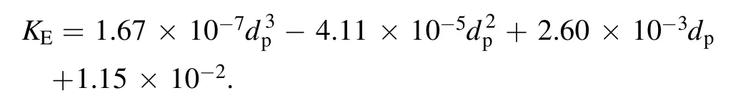
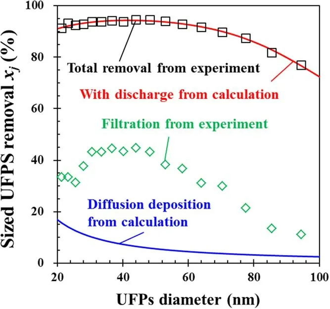
Figure 12.Comparison of the calculation results with the experimental results as per figure 6.
In brief,the removal efficiency with particle size distribution was consistent with the calculatedKEvalues versus particle sizes,verifying that the total UFP removal cannot approach 100%.
4.Conclusions
In this study,five types of DBD reactor coupled with or without PA balls were developed to remove the UFPs from the exhaust gases of kerosene combustion.The total UFP removal was enhanced to above 90% due to the particle charging.The charged particles could be immediately collected by the PA balls via the electrostatic force in the DBD reactor.Peak voltages,pulse frequency and gas flow rate had less influence on the total UFP removal.The UFP removal by diffusion deposition and electrostatic attraction were further calculated,showing that the particle charging is very important to the high removal efficiency of UFPs.This study provides the practical application of a DBD reactor packed with PA balls to remove the UFPs from an exhaust gas.
Acknowledgments
This project was funded by the Open Foundation of Engineering Research Center of Construction Technology of Precast Concrete of Zhejiang Province(No.ZZP1902).
猜你喜欢
杂志排行

Plasma Science and Technology的其它文章
- Numerical simulation of carbon arc discharge for graphene synthesis without catalyst
- Visualization of gold nanoparticles formation in DC plasma-liquid systems
- Rice plant growth and yield:foliar application of plasma activated water
- An active tunable Fano switch in a plasmafilled superlattice array
- Comparison of sample temperature effect on femtosecond and nanosecond laser-induced breakdown spectroscopy
- Magnetic field induction and magnetic force distribution profiles in plasma focus discharge device