Influence of non-uniform electric field distribution on the atmospheric pressure air dielectric barrier discharge
2021-07-07WeishengCUI崔伟胜ShuaiZHAO赵帅ZhengfangQIAN钱正芳YilingSUN孙一翎MahmoudALSALIHIandXiangquanDENG邓想全
Weisheng CUI(崔伟胜),Shuai ZHAO(赵帅),Zhengfang QIAN(钱正芳),Yiling SUN(孙一翎),Mahmoud AL-SALIHI and Xiangquan DENG(邓想全)
1 Key Laboratory of Optoelectronic Devices and Systems of Ministry of Education and Guangdong Province,College of Physics and Optoelectronic Engineering,Shenzhen University,Shenzhen 518060,People’s Republic of China
2 Aerospace Information Research Institute,Chinese Academy of Sciences,Beijing 100094,People’s Republic of China
Abstract The dielectric barrier discharge(DBD)in air at atmospheric pressure is not suitable for industrial applications due to its randomly distributed discharge filaments.In this paper,the influence of the electric field distribution on the uniformity of DBD is theoretically analyzed and experimentally verified.It is found that a certain degree of uneven electric field distributions can control the development of electron avalanches and regulate their transition to streamers in the gap.The discharge phenomena and electrical characteristics prove that an enhanced Townsend discharge can be formed in atmospheric-pressure air with a curved-plate electrode.The spectral analysis further confirms that the gas temperature of the plasma produced by the curved-plate electrode is close to room temperature,which is beneficial for industrial applications.This paper presents the relationship between the electron avalanche transition and the formation of a uniform DBD,which can provide some references for the development and applications of the DBD in the future.
Keywords:dielectric barrier discharge,electric field distribution,electron avalanche,Townsend discharge
1.Introduction
The atmospheric pressure non-equilibrium plasma is at room temperature and can generate high-energy electrons,ultraviolet radiation photons,and a variety of high-energy active particles.Therefore,it can be effectively used for disinfection and sterilization[1,2],material surface modification[3–5],catalytic decomposition of pollutants[6–9],etc.The dielectric barrier discharge(DBD)has the characteristics of simple structure,wide application range,scalability and it is the most desirable generation method of non-equilibrium plasma for industrial applications[10–12].However,the air,as the most promising work gas,consists of oxygen with a high electron affinity,which can effectively quench the metastable nitrogen species and bind with the free electrons,thus reducing the free electron density.The DBD in air under atmospheric pressure usually exhibits a lot of randomly distributed discharge filaments,affecting the treatment effect and even causing damages to the treated materials[13].
Many methods have been explored to achieve a uniform DBD in air at atmospheric pressure.It is found that the discharge characteristics of the atmospheric pressure DBD are mainly determined by the electron avalanche development,which is closely related to its time and spatial scales.The utilization of nanosecond pulsed voltage waveform can restrain the development of electron avalanches in the nanosecond time scale,preventing the generation of local high density charged particles[14,15].In recent years,with the advance of the power electronics technology,the research of atmospheric pressure DBD based on nanosecond pulsed power supply has been widely carried out[11,16–18].However,nanosecond pulsed power supplies are costly,limited in power,and susceptible to electrode structure because of the capacitive load and the nanosecond voltage rise time.As a result,they cannot satisfy the requirements for large-scale industrial applications.
The low-cost and high-power low-frequency AC power supply has distinct advantages in the industrial application prospect.However,on one hand,the commonly used low-frequency AC power supply(e.g.20 kHz or less)has a microsecond pulse duration time and cannot restrain the excessive development of electron avalanches on the time scale.On the other hand,the mean free path of the air is only about 68 nm due to its high molecular density[19],making it hard to form a practically applicable uniform DBD at atmospheric pressure in air by limiting the spatial scale of the electron avalanches[20–22].
The seed electron density has been proved to play a vital role in generating a uniform DBD in atmospheric-pressure air[23–28].Many researchers took the advantages of the electrons provided by the surface of dielectric barriers to improve the uniformity of the DBD.For example,Luo[29]utilized the effect of‘shallow traps’[26]on the surface of unique alumina ceramics to supply additional seed electrons and formed a homogeneous Townsend discharge in air.However,the Townsend discharge with the ‘shallow traps’ is very weak,hardly visible to the naked eyes,and is not reliable for industrial applications[24,28,30].
The electrode structures with non-uniform electric fields have been utilized in many aspects[31–35],while the influence of electric field distribution on the uniformity of DBD is seldom systematically analyzed.With regard to this situation,we designed non-uniform electrode structures,and investigated the influence of different electric field distributions on the discharge.Through the theoretical calculation,the relationship between the electric field distribution and the transition of electron avalanches was obtained.The discharge experiments corresponding to the preceding theoretical analysis were also carried out,and a practically applicable Townsend discharge in a maximum of 3 mm gap was achieved in atmospheric-pressure air.
2.Experimental setup
The experimental setup in this research is shown in figure 1(a).The CTP-2000 K was used as the power supply,which has a sinusoidal voltage output with a maximum amplitude of 30 kV and a frequency of 6 kHz.The voltage applied between the electrodes was obtained by a capacitive voltage divider,and the discharge current was obtained by a 50 Ω resistor in series with the discharge circuit.A plate electrode,an uneven-plate electrode and a curved-plate electrode were designed in this research,as shown in figure 1(b).The electrode structures were obtained by the processing of two vertically placed PTFE panels.The rectangular and arc-shaped grooves were set on the contacting surface for the plate electrode and uneven-plate electrode.The curved-plate electrode was made from two curved-shaped plates with a thickness of 1 mm on the basis of the uneven-plate electrode.The PTFE panel size is 20 mm×30 mm×2.5 mm,and the depth,width,and length of the groove are 1.5 mm,12 mm,and 20 mm,respectively.The high voltage and the ground electrodes were made of copper sheets and fixed on the outer surface of PTFE.The discharges were carried out in air,and the pressure,temperature,and relative humidity are 1.01×10⁵Pa,25 °C and 80%,respectively.
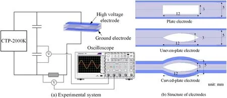
Figure 1.The experimental setup.
3.Theoretical analysis
3.1.The electric field distribution
The ANSYS Maxwell software was used to obtain the spatial electric field distribution of the three electrode structures.The distribution of the electric field intensity of the cross-section for the three electrode structures with an applied voltage of 11 kV is depicted in figure 2.

Figure 2.The distribution of electric field intensity for(a)plate electrode,(b)uneven-plate electrode and(c)curved-plate electrode.
It can be seen from figure 2 that the plate electrode has the lowest electric field intensity,and the distribution is relatively uniform.However,the curved-plate electrode and the uneven-plate electrode exhibit a higher electric field intensity and a distinct non-uniform electric field distribution.Drawing a line on the contact plane of the dielectrics along theX-axis,the electric field intensities along the line for the three electrode structures are shown in figure 3.
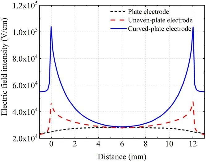
Figure 3.The distribution of electric field intensity along the drawing lines.The line was in the contacting plane of the dielectrics and went across the gap along the X-axis.
As demonstrated by figure 3,the electric field intensity is approximately uniform for the plate electrode with the value in the central region slightly higher than that at both ends.In contrast,the uneven-plate electrode and the curved-plate electrode exhibit much higher electric field intensity in the narrow gaps at both ends than that in the central region,reaching about 1.6 times and 3.8 times the maximum electric field intensity of the plate electrode,respectively.
3.2.Theoretical analysis on electron avalanches
The electron avalanche development was theoretically analyzed based on the gas discharge theory[36,37].According to the distribution of electric field vectors,the electron collision ionization paths can be determined.
The collision ionization coefficient α at atmospheric pressure in air can be obtained by the empirical values when
Eranges from 1.5×10⁴to 1.1×10⁵V cm−1[38].Different electron avalanche development paths along theX-axis were set to investigate the electron avalanche development in different positions.A spacing of 0.2 mm was adopted to eliminate the mutual interaction of electron avalanches in the development based on the previous analysis.
The electron collision ionization process can be analyzed by Townsend discharge theory.The number of electrons increases exponentially with the development distance of the electron avalanche.However,in atmospheric pressure condition,the external electric fieldEextwill be distorted by space charge electric fieldEcbecause of the numerous electrons produced in the electron avalanche.Based on the Meek criterion[37],whenthe electric field will be substantially distorted,and the electron avalanche will transit to a streamer.
The produced electrons diffuse in the radial direction and shape like a sphere during the development of electron avalanches where the electrons are assumed to be evenly distributed in the head.The ions consist of many ion spheres along the development paths.Therefore,the space charge electric field is the comprehensive result of the electrons in the head of the electron avalanche and the ion spheres along the development path.Performing integration calculation,the electric field in the head of the electron avalanche caused by the space electrons and ions can be simplified as
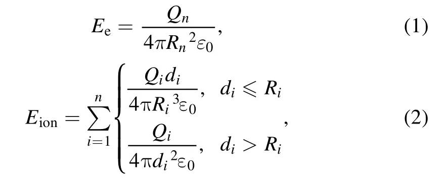
where,EeandEionare the electric field strength at pointPnproduced by electrons and ions,respectively.Qnis the charges of electrons in the head of the electron avalanche.QiandRiare the charges and the radius of theith ion sphere,respectively,anddiis the distance between the center of theith ion sphere and the pointPn.ε0is the permittivity.Therefore,the electric field responsible for the electron collision ionization should be the combined effect ofEext,EeandEion.
In addition,the space charges produced in the previous period and the dielectric surface charge should be taken into consideration.It was known that the ion mobility was usually not affected by the electric field in the wide range[37]and the positive ion mobility in the air was 1.36×10⁻⁴m2V−1·s−1.According to reference[25],when the voltage drop in the gap was set to 11 kV,the maximum escaping time of ions in the preceding electrode structure was calculated to be 18 μs.It is much smaller than the period of the applied voltage(about 167 μs).The electron mobility is much higher than ion mobility.Therefore,the influence of residual space charge can be ignored.Based on the previous research[24],the surface charge density of PTFE could reach 8 pC mm−2.The surface charge adhered during the discharge could also influence the intensity of the spatial electric field.According to the surface electron charge density,the surface charge electric field was calculated to be 9.035×10³V cm−1,which is independent of the gap size.According to the previous analysis,the transition distribution of the electron avalanches can be analyzed.
3.3.Transition of electron avalanches to streamers
In order to estimate the electron avalanche transition patterns of the electrode structures,the coefficient of viable seed electron was assumed to be 0.01 of the surface electrons.The development of electron avalanches can be obtained by Matlab iterative calculation.If the Meek criterion is reached before the electron avalanche develops to the upper surface,it indicates that the electron avalanche will transit to a streamer and the calculation stops.Otherwise,the electron avalanche remains,and the Townsend discharge was formed.The spatial electric field distribution for the three electrode structures with an applied voltage of 11 kV is shown in figure 4.
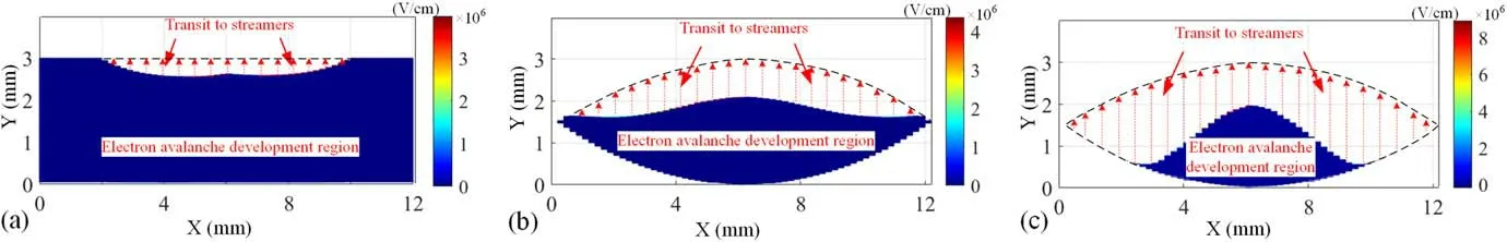
Figure 4.The space charge electric field distribution after the development of electron avalanches for(a)plate electrode,(b)uneven-plate electrode,and(c)curved-plate electrode.The dash line indicates the gap profile.The regions with red dash arrows indicate that the electron avalanches transit to streamers.
Figure 4 shows that the occurrence of electron avalanches transiting to streamers exhibits less difference in the plate electrode.While,the transitions of electron avalanches in the uneven-plate electrode and the curved-plate electrode vary significantly and the electron avalanches in the narrow gaps are more inclined to transit to streamers.All of the electron avalanches in the uneven-plate electrode transit to streamers in the middle of development.With the increase of the unevenness of the electric field,most of the electron avalanches development in the narrow gaps of the curvedplate electrode are promoted notably and transit to streamers quickly and the ones in the central region are less affected.Besides,it has been seen that the maximum electric field for the three electrode structures appeared very close to the transition positions,which is caused by the electron concentrations in the head of the electron avalanches.
Changing the applied voltage,the variation of electron avalanche transition distributions for the three electrode structures was calculated and depicted in figure 5.The transition point of each electron avalanche with the same voltage was connected to differ from that of other voltages.
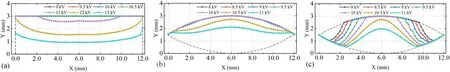
Figure 5.The variation of transition distribution of electron avalanche for(a)plate electrode,(b)uneven-plate electrode,and(c)curved-plate electrode with different applied voltages.The dash line indicates the gap profile.The transition point of each electron avalanche with the same voltage was connected to differ from that of other voltages.
It can be seen from figure 5 that the electron avalanches in the plate electrode transit to streamers approximately at the same distance when the applied voltage exceeds 11 kV.Due to the large discharge gap,it is estimated that the fierce filamentary discharge is more easily formed in the gap.The transitions of the electron avalanches in the uneven-plate electrode occur at a lower voltage.Nevertheless,most of the electron avalanches in the central region transit to streamers simultaneously,which may lead to the same results with the plate electrode.Because of the most uneven electric field distribution among the three electrode structures,the curvedplate electrode presents a distinct gradual transition characteristic of electron avalanches with different applied voltages.The transition first occurs in the narrow gaps at the ends and expands to the central region with the increase of the applied voltage.It indicates that the electron avalanches in the narrow gaps will transit to streamers firstly,while the central region can remain in Townsend discharge mode.
The partial electron avalanche transition will lead to the non-uniform distribution of produced electrons.The electrons first produced in the streamers can diffuse to other weak discharge regions and enhance the intensity of the Townsend discharge.The distribution of produced electrons for the three electrode structures was depicted in figure 6 with the applied voltage of 11 kV,10 kV,and 8 kV,respectively.

Figure 6.The number of produced electrons for(a)plate electrode,(b)uneven-plate electrode,and(c)curved-plate electrode with the applied voltage of 11 kV,10 kV,and 8 kV,respectively.The Z-axis indicates the number of electrons.
Figure 6 demonstrates that a large number of electrons are distributed in the whole gap of the plate electrode due to the electron avalanche transition.It is more likely to accelerate the development of streamers.By comparison,the produced electrons in the uneven-plate electrode and the curved-plate electrode are primarily distributed in the narrow gaps at the ends and the electrons in the curved-plate electrode were more concentrated.During the discharge,the narrow gaps will discharge first and diffuse the produced electrons,which makes it the function of the seed electron source.
4.Discharge characteristics
4.1.Discharge phenomena and light emission analysis
The preceding theoretical analysis indicates that the curvedplate electrode can regulate the transition of electron avalanches and inhibit the formation of large-area discharge streamers.The discharge experiments were carried out to validate this inference.The discharge phenomena and the light emission analysis with short exposure time for the three electrode structures are shown in figure 7.
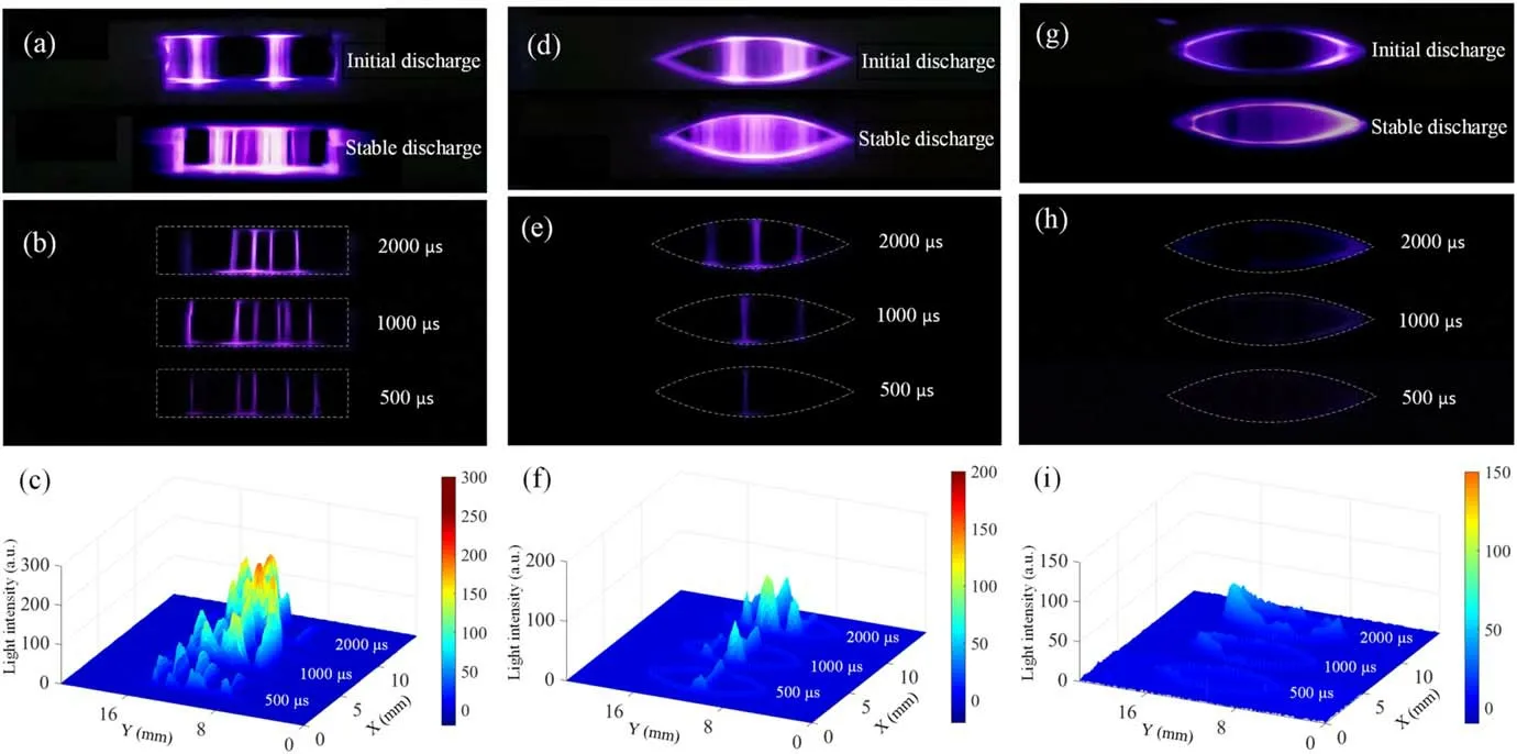
Figure 7.The discharge phenomena for plate electrode(a)–(c),uneven-plate electrode(d)–(f)and curved-plate electrode(g)–(i).(a),(d)and(g)are the discharge phenomena(exposure time:58 ms)of the three electrode structures.(b),(e)and(h)are the light emission images of stable discharge with short exposure time for the three electrode structures,and(c),(f),and(i)are the data analyses of corresponding light emission images.The dash lines in(b)–(c),(e)–(f),and(h)–(i)indicate the gap profile.
The plate electrode exhibited fierce filamentary discharge as presented in figure 7.The discharge occurred quickly above 11 kV,and numerous short-lived discharge filaments were randomly distributed in the gap.The short-exposure light emission images with a minimum of three cycles were recorded,and the data analyses were performed,which showed explicit characteristics of discharge filaments.The uneven-plate electrode first displayed visible discharge near the narrow gaps above 10 kV and also formed discharge filaments when stable discharge was achieved.The shortexposure light emission images captured the visible discharge filaments with less intensity than that of the plate electrode.The curved-plate electrode first showed bright discharges in both narrow gaps at less than 9 kV,and a diffuse discharge expanded towards the central region with the increase of the applied voltage.The whole gap was filled with a relatively homogeneous discharge visible to the naked eyes at about 10 kV.The discharge phenomena and its development process are consistent with the transition patterns analyzed in section 3.3.In the short-exposure light emission images with three discharge cycles,no discharge filaments were found,and a weak luminous layer close to the edge of the gap was revealed.Therefore,it is demonstrated that with the increase of the unevenness of the electric field,the formation of discharge filaments was effectively inhibited.A relatively homogeneous Townsend discharge was formed in the curvedplate electrode.
4.2.Electrical characteristics
The characteristics of the discharge current waveforms correspond with the discharge phenomena,as shown in figure 8.It has been seen that the current waveform of the plate electrode exhibited a lot of large ‘spikes’,which was induced by the fierce filamentary discharge.The number of the spikes was reduced in the current waveform of the uneven-plate electrode,which was due to the lower discharge voltage and the weaker filamentary discharge intensity.The spikes in the current waveform of the curved-plate electrode were nearly eliminated,indicating that most of the discharge filaments were effectively inhibited.The voltage and current waveforms characteristics for the three electrode structures were consistent with the light emission data.The curved-plate electrode can regulate electron avalanches’ transition to streamers with the non-uniform electric field distribution and form an enhanced atmospheric pressure Townsend discharge in air.
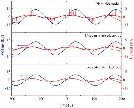
Figure 8.The waveforms of discharge voltage and current for the three electrode structures with stable discharges.
4.3.Spectral analysis
The optical emission spectra with a resolution of 0.02 nm(grating:1200 g mm−1;slit width:20 μm)were used to characterize the plasma generated in the three electrode structures,as shown in figure 9.The emission spectra in the wavelength from 300 nm to 480 nm were collected,and the excited species such as OH,N2,N2+were depicted.The excited particles were produced by the energetic collisions of electrons with the N2,O2,and H2O molecules in the ambient air.The gas temperature was obtained through the rotational temperature,which was obtained by comparing the simulated spectra ofwith the experimentally recorded spectra[39,40]with the software Specair[41].When the best fit was achieved,the rotational and vibrational temperature of nitrogen can be obtained[42].It showed that the vibrational temperature was much higher than the rotational temperature,indicating that the plasma is under non-equilibrium conditions and has enhanced plasma chemical activity.Furthermore,the gas temperature of the curved-plate electrode was close to room temperature,showing a significant decrease compared with that of the plate electrode,which indirectly implied that the fierce filamentary discharge was suppressed.

Figure 9.OES of DBD for(a)the three electrode structures and(b)the rotational and vibrational temperature obtained by comparing the simulated spectra of the with the experimental recorded spectra.
5.Conclusion
In summary,the influence of the non-uniform electric field on the uniformity of atmospheric pressure DBD in air was performed.Through the theoretical calculation,the transition pattern of the electron avalanches in the gap was analyzed.The experimental results have been proved to be in good agreement with the preceding theoretical analysis.The relatively uniform Townsend discharge at atmospheric pressure was achieved in air with a simple electrode structure,which can provide some references for the development and application of DBD in the future.
Acknowledgments
This work was supported by the Science and Technology Innovation Commission of Shenzhen(No.JCYJ20180507181858539),Shenzhen Science and Technology Program(No.KQTD20180412181422399),and the National Key R&D Program of China(No.2019YFB2204500).
ORCID iDs
杂志排行

Plasma Science and Technology的其它文章
- Numerical simulation of carbon arc discharge for graphene synthesis without catalyst
- Enhanced removal of ultrafine particles from kerosene combustion using a dielectric barrier discharge reactor packed with porous alumina balls
- Visualization of gold nanoparticles formation in DC plasma-liquid systems
- Rice plant growth and yield:foliar application of plasma activated water
- An active tunable Fano switch in a plasmafilled superlattice array
- Comparison of sample temperature effect on femtosecond and nanosecond laser-induced breakdown spectroscopy