Experiment on low-frequency electromagnetic waves propagating in shock-tube-generated magnetized cylindrical enveloping plasma
2021-07-07ShaoshuaiGUO郭韶帅KaiXIE谢楷BinSUN孙斌RuoyaoXI席若尧andYanLIU刘艳
Shaoshuai GUO(郭韶帅),Kai XIE(谢楷),Bin SUN(孙斌),Ruoyao XI(席若尧)and Yan LIU(刘艳)
School of Aerospace Science and Technology,Xidian University,Xi’an 710071,People’s Republic of China
Abstract We propose a method of applying a static magnetic field to reduce the attenuation of the magnetic field component(SH)of low-frequency electromagnetic(LF EM)waves in dense plasma.The principle of this method is to apply a static magnetic field to limit electron movement,thereby increasing the equivalent resistance and thus reducing the induced current and SH.We consider the static magnetic field acting on the plasma of the entire induced current loop rather than on the local plasma,where the induced current is excited by the magnetic field component of LF EM waves.Analytical expressions of SH suitable for magnetized cylindrical enveloping plasma are derived by adopting an equivalent circuit approach,by which SH is calculated with respect to various plasma parameter settings.The results show that SH can be reduced under a static magnetic field and the maximum magnetic field strength that mitigates blackout is less than 0.1 T.Experiments in which LF EM waves propagate in a shock-tubegenerated magnetized cylindrical enveloping plasma are also conducted.SH measured under the magnetic field(the magnetic field strengthB0 acting on the magnetic field probe was about 0.06 T)reduces at f=10 MHz and f=30 MHz when ne≈1.9×1013 cm−3,which is consistent with theoretical results.The verification of the theory thus suggests that applying a static magnetic field with a weak magnetic field has the potential to improve the transmission capacity of LF EM waves in dense plasma.
Keywords:static magnetic field,shock tube,low-frequency electromagnetic waves,cylindrical enveloping plasma
1.Introduction
Reducing the attenuation of the penetration of electromagnetic(EM)waves through a plasma sheath has attracted much attention from researchers in the past few decades.To achieve the uninterrupted monitoring of spacecraft re-entries,researchers have proposed and tested a series of methods that mitigate blackout,including methods based on aerodynamic shaping[1],electrophilic injection or ablation[2,3],magnetic windows[4–15],high-frequency transmissions[16,17],and surface catalysis effects[18].The potential of the low-frequency(LF)EM wave has not attracted much attention because the LF antenna is large and the amount of information transmitted is small[19,20].
We recently found that an LF wave has special propagation characteristics when the plasma sheath is electrically small compared with the wavelength.In this case,the LF wave has different attenuation mechanisms in terms of the magnetic field component and electric field component,in which the attenuation of the magnetic field component(SH)is much less than the attenuation of the electric field component(SE)[21–23].The frequency band for communication reaches the MHz level.We conducted a shock tube experiment to prove the theory,where the frequency of LF EM waves ranged from 1 to 30 MHz.Related research results can be used for minimal communications(e.g.voice data)during re-entry or entry flights.
In order to further reducingSHunder high electron density,one of the more promising methods may be the magnetic window.SHis generated by a reverse magnetic field formed by induced current in the plasma and weakens the original magnetic field signal.It is therefore possible to decreaseSHby reducing the induced current,which can be achieved by increasing the equivalent resistance of the plasma.The magnetic window method can reduce conductivity by limiting the movement of electrons or reducing the electron density to increase the equivalent resistance of the plasma[4,5,9,10].
On the above basis,SHcan be reduced by adopting the magnetic window method.The E×B method proposed by Kimet alcan generate E×B drift to reduce the electron density[9,10].The result of reducing the electron density is that the conductivity decreases and the resistance increases.Although this method can reduce the induced current,the static electric field is restricted by the Debye shielding effect under a high electron density.The time-varying magnetic field method put forward by Stenzelet alcan generate Hall drift and thus also reduce the local electron density and conductivity,but the duration of the magnetic field is only tens of microseconds,which does not allow continuous mitigation[24].The static magnetic field mitigating method was proposed in the 1960s[4].Russo and Hughes then conducted experimental tests to demonstrate that static magnetic fields can improve the propagation of EM waves by limiting electron movement and thus make it difficult for free electrons to interact with the electric field component of EM waves[5].Therefore,the static magnetic window method can also reduce conductivity.
The present paper aims to apply a static magnetic field to limit electron movement in plasma and thus reduce the induced current and mitigateSHunder a high electron density.Since the attenuation mechanism ofSHdiffers from that of conventional frequency bands(e.g.the S-band)and it is mainly affected by the induced current that is excited by the magnetic field component of LF EM waves[21–23].We thus consider that the static magnetic field acts on the plasma of the entire induced current loop rather than on the local plasma in this paper.Furthermore,SHhas proven to be sensitive to the geometry of the enveloping plasma because the flow path of the induced current closely correlates with the plasma shape[3].This paper therefore explores the characteristics of LF EM waves propagating in a shock-tube-generated magnetized cylindrical enveloping plasma.
We first construct a model of EM waves propagating in a magnetized cylindrical enveloping plasma,and we use an equivalent circuit to derive the analytical solution ofSH.In this way,we further analyze the effect of external magnetic field imposed on the attenuation characteristics of LF EM waves propagating in the cylindrical enveloping plasma.
We then propose an experimental method using the shock-tube-generated magnetized cylindrical enveloping plasma to confirm the validity of the theory.
The remainder of this paper is organized as follows.Section 2 presents analytical expressions ofSHthat are suitable for a magnetized cylindrical enveloping plasma.Section 3 simulates the effect of magnetic field on LF EM waves propagating in the magnetized cylindrical enveloping plasma.Section 4 conducts the experiment using a shock tube[25–28].Section 5 outlines the discussion.Section 6 conclusion of this study.
2.Analytical expression of SH for magnetized cylindrical enveloping plasma
2.1.Analytical expressions of SH for non-uniform magnetized plasma
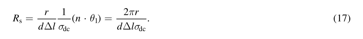
The magnetic field component of LF EM waves induces a circulating current in plasma as shown in figure 1(a).Since the permeability of the plasma is the same as the vacuum,the magnetic field component of LF EM waves is continuous at the boundary.SHcan be evaluated from the ratio of[21,22,29]:
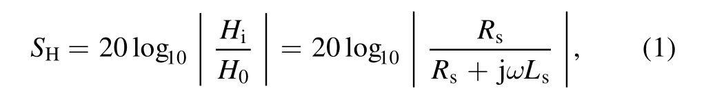
Here,Hiis the magnetic field strength at the center of the cylinder,H0is the initial magnetic field strength of LF EM waves.The loop inductanceLsof the induced current can be expressed as
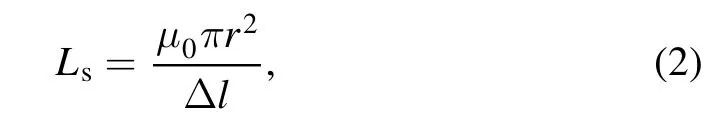
whereμ0is the permeability of a vacuum,Δlis the length infinitesimal of a cylinder,andris the outer radius of the cylinder.
In the above equation(1),Rsdenotes the equivalent resistance of the entire flow path of the induced current in the plasma.When the external static magnetic field acts on the cylindrical enveloping plasma,the conductivity σ of the plasma can be regarded as a tensor,and the equivalent resistanceRschanges.In this circumstance,the current induced on the surface of the cylindrical enveloping plasma under the effect of the static magnetic field changes accordingly(where the induced current density is shown in figure 1(a)),thereby changing the magnetic field component of LF EM waves inside the cylindrical enveloping plasma.The above process is expressed as the equivalent circuit shown in figure 1(c).
As the static magnetic field gradually decreases along the direction of the magnetic field lines,the magnetic field is nonuniformly distributed in space.Owing to the different magnetic field points on the current loop,the value of equivalent resistance may therefore differ at each point on the loop.First,we simplify the model and divide the induced current loop intonsegments equally(as shown in figure 1(b)).The arc of each segment is θ,whose equivalent resistance is defined as ΔRsi(i=1,2 ….n,n=2π/θ).We then choose a field point on each arc segment,which is denotedBi(i=1,2….n,n=2π/θ).The equivalent resistance of the entire loop is expressed as
wheren=2π/θ,and the equivalent resistance ΔRsof a single arc is obtained via the following analysis.
The induced current path on thex–yplane is shown in figure 1,where it is seen that there is no current component in thezdirection,suggestingJz=0.Hence,JxandJyare expressed as

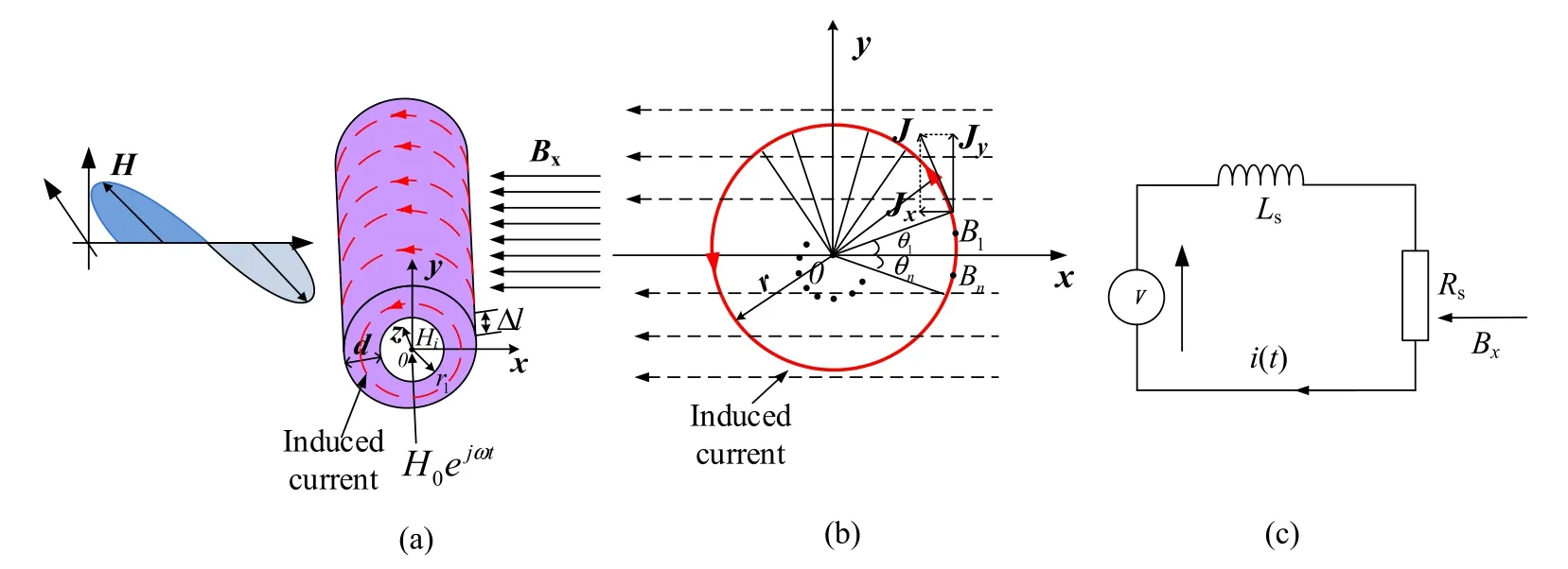
Figure 1.(a)Simplified model of the magnetic field component of the LF plane wave incident on the cylindrical enveloping plasma;(b)simplified model of the effect of uniform magnetic field on induced circulation;(c)schematic diagram of the equivalent circuit model.
where ΔS=d·Δlis the cross-sectional area through which the current flows,dis the thickness of plasma,Δlis the length micro-element of cylinder.
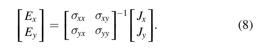
According to Ohm’s law,the current density is expressed as
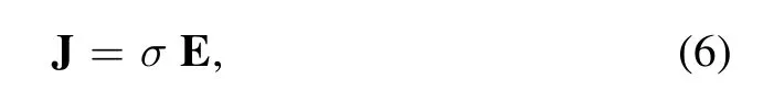
and the current density on thex–yplane is
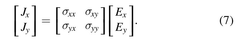
It follows from equation(7)that
The potential at a point on the circulating current of thex–yplane is expressed as
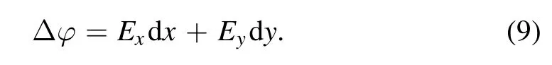

Using equations(4),(5)and(8)–(10),the circulating current resistance is expressed as
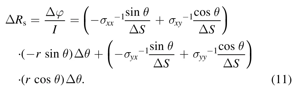
By solving equation(11),we obtain

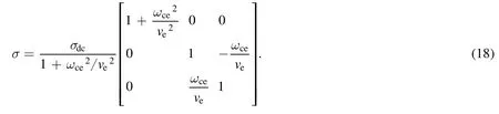
whereris the outer diameter of the cylinder.The plasma conductivity σ is a tensor under an external magnetic field and is expressed as

whereveis the electron collision frequency,andaandcare further expressed as
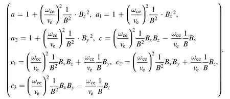
The external static magnetic field acts on the cylindrical enveloping plasma,the conductivity σ of plasma is a tensor,and the plasma has different conductivity when the static magnetic field is applied from different directions.We therefore separately derive analytical expressions ofSHfor a static magnetic field on thex-axis,y-axis,andz-axis.
2.1.1.Analytical expressions of SH for a static magnetic field on the z-axis.We first regard the external static magnetic field as one-dimensional and non-uniformly distributed along thezdirection;that is,Bz=BandBx=By=0.The conductivity σ is written as
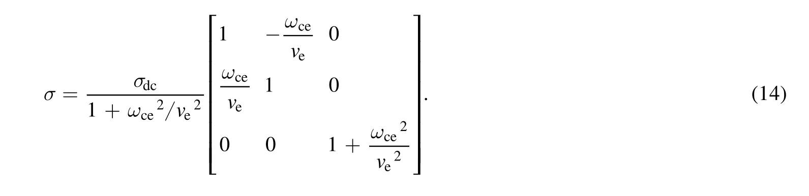
We obtain from equation(14)the inverse matrix of the conductivity on thex–yplane
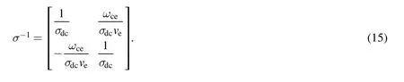
Then,using equations(3),(12),and(15),we obtain the equivalent resistanceRsas
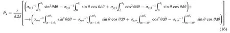
By solving equation(16),the equivalent resistanceRson thez-axis is rewritten as
When the static magnetic field is distributed along thez-axis,we find that the equivalent resistanceRsis identical to that for the situation in which no magnetic field is applied,thereby suggesting thatSHis not affected when the external magnetic field is distributed along thez-axis.
2.1.2.Analytical expressions of SH for a static magnetic field on the x-axis or y-axis.SHfor magnetized cylindrical enveloping plasma remains unchanged owing to symmetry when applying the external static magnetic on thex-axis ory-axis.Taking the magnetic field applied to thex-axis as an example,we analyze the effect of the static magnetic field onSH.When the static magnetic field is distributed along the direction of thex-axis,Bx=BandBy=Bz=0.The conductivity σ is expressed as
We obtain from equation(18)the inverse matrix of conductivity on thex–yplane

Then,using equations(3),(12),and(19),we obtain the equivalent resistanceRsas

We therefore obtainSHfor a non-uniform magnetic field as
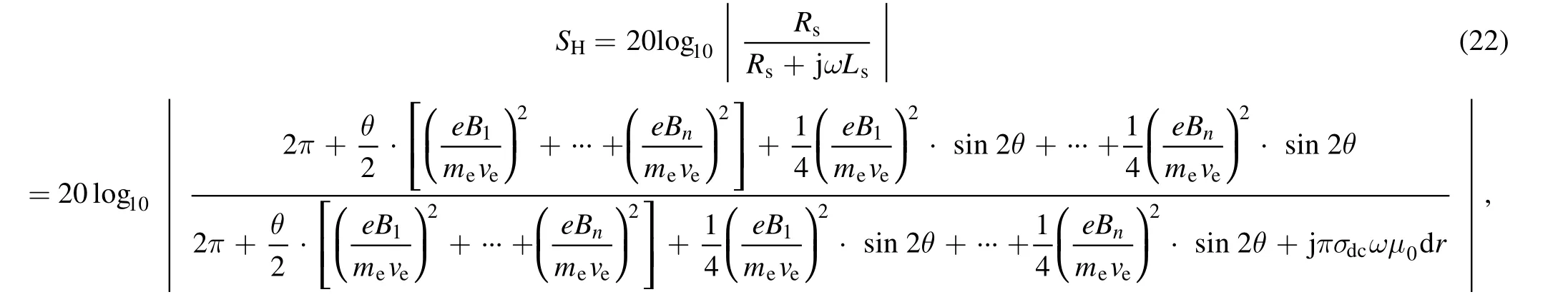
where ω=2πf.WhenB=0,the expression forSHis the same as that in[3].
3.Simulation of LF EM wave propagation in uniform magnetized cylindrical enveloping plasma
Various plasma parameters are established using the analytical solution,to evaluate the effect of a uniform static magnetic field on LF EM wave propagation in cylindrical enveloping plasma under conditions off=10 MHz andf=30 MHz,when the external magnetic field is distributed along thex-axis(B1=B2=…….Bn=B(n=2π/θ),θ=2π).We suppose a cylindrical plasma for which the radiusr1is 1 cm,the plasma thicknessdis 3 cm,the cylinder lengthlis 20 cm,the electron densityneranges from 5×10¹²to 2×1013cm−3,the static magnetic fieldBranges from 0 to 1 T.The collision frequency is determined by the formulawherePis the gas pressure(Pa),Teis the electron temperature(K),P0=101 324 Pa is the atmospheric pressure.The simulation conditions wereTe=1000 K,and the pressures are assumed to be 60 Pa,600 Pa,6000 Pa,respectively.
The effect of the static magnetic field onSHis shown in figure 2.It is seen thatSHgradually decreases with an increase in the magnetic field strength.For instance,with respect to a cylindrical enveloping plasma to which no magnetic field is applied,supposing that its electron density and pressure arene=2×1013cm−3andP=60 Pa respectively,the LF EM wave attenuation still exceeds 30 dB.The value of −30 dB is taken as the threshold for judging whether the problem of radio blackout emerges,which suggests that the magnetic field component of LF EM waves still suffers radio blackout under high electron density[11,30].SHchanges appreciably when applying a magnetic field to the plasma.For instance,in the case thatne=2×1013cm−3andP=60 Pa,∣S∣Hreduces from 42 to 20 dB with an applied static magnetic field of only approximately 0.017 T atf=30 MHz.
A reasonable explanation of the above is as follows.Owing to the effect of the static magnetic field,free electrons twirl around the magnetic field lines,which hinder the free motion of charged particles along the vertical direction of the static magnetic field.However,the movement of free electrons parallel to static magnetic field is not affected,reducing conductivity perpendicular to the static magnetic field.Therefore,the conductivity remains unchanged along the direction of the magnetic field.In the above circumstances,the equivalent resistance of the entire induced current flow path becomes larger,thereby reducing the induced current andSH.
Figure 2 reveals that as the magnetic field strengthens,SHis reduced more readily at a low pressure than at a high pressure.As an example,whenf=10 MHz andne=2×1013cm−3,the critical magnetic field strength at which there is a sharp decrease inis merely 0.003 T atP=60 Pa.When the pressure increases to 600 Pa,then the critical strength of the magnetic field increases to 0.021 T.As the pressure further increases to 6000 Pa,the critical strength of the magnetic field accordingly increases to 0.16 T.Despite the fact that the strength of the applied magnetic field required for an appreciable reduction inat a high pressure is far higher than that at a low pressure,is small at a high pressure and it is thus reasonable and possible to apply a weak magnetic field to alleviate radio blackout that occurs under a high electron density.
Comparing figure 2(a)with figure 2(b)reveals thatSHincreases with the EM wave frequency.Under the effect of a static magnetic field,SHreaches the same level as that at a low EM wave frequency.For instance,in the case ofne=2×1013cm−3andP=60 Pa,∣S∣Hreduces from 42 to 20 dB withatf=30 MHz,which is only 0.008 T more than that atf=10 MHz.Although a stronger magnetic field is required at a higher EM wave frequency to reduceto the same level as that at a lower EM wave frequency,the available frequency band becomes wider,thereby increasing the amount of information being transmitted.

Figure 2.The attenuation of SH functioning as the magnetic field with pressure as its parameter.(a) f=10 MHz,(b) f=30 MHz.
Figures 3 and 4 reveal that the electron density of plasma also affects the effect of the magnetic field imposed onSH,wheregradually increases with the electron density when applying no static magnetic field.After applying the magnetic feild,decreases drastically with an increase in the magnetic field strength.To achieve the same improvement,the static magnetic field required in circumstances of high electron density is stronger than that in circumstances of low electron density.

Figure 3.The attenuation of SH functioning as a magnetic field with electron density as its parameter for f=10 MHz.(a) P=60 Pa,(b) P=600 Pa.

Figure 4.The attenuation of SH functioning as a magnetic field with electron density as its parameter for f=30 MHz.(a) P=60 Pa,(b) P=600 Pa.
4.Experiment and results
4.1.Experimental setup
The relatively uniform high-temperature gas behind a strong shock wave in a shock tube with a diameter of 80 mm was used as the experimental plasma.The detailed structure of the shock tube and process of generating the plasma were presented in[3,4].The specific experimental parameter values before and after applying the magnetic field are listed in table 1,vis thevelocity of shock wave,tis the duration of the plasma.The LF EM waves were generated by a radio-frequency signal generator and emitted by a loop antenna located 35 m outside the shock tube(as shown in figure 5).In the experiment,the transmitted signal was generated by combining LF signals at two frequencies together,and the transmitted signal is expressed aswhere the frequencies of LF signals aref1=10 MHz,f2=30 MHz,respectively.The magnetic field component of LF EM waves was received by a field strength probe(as shown in figure 7)mounted in the shock tube(as shown in figure 6).The structure of the field probe is shown in figure 7(b).The working mechanism is to induce a voltage signal of the magnetic field component of the LF EM wave through closed coils.The detailed probe structure and calibration of the magnetic field probe were presented in[4].The field strength probe was connected to an amplifier,thereby obtaining amplified magnetic signals from the amplifier of an oscilloscope.
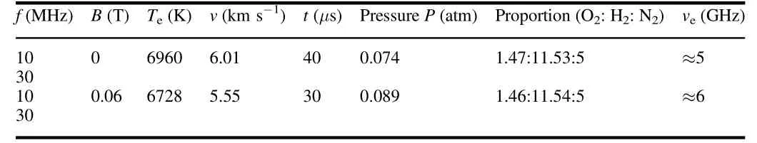
Table 1.State parameters of shock tube.
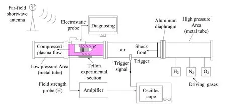
Figure 5.Experiment setup with a diameter of 80 mm shock tube and measuring instruments.
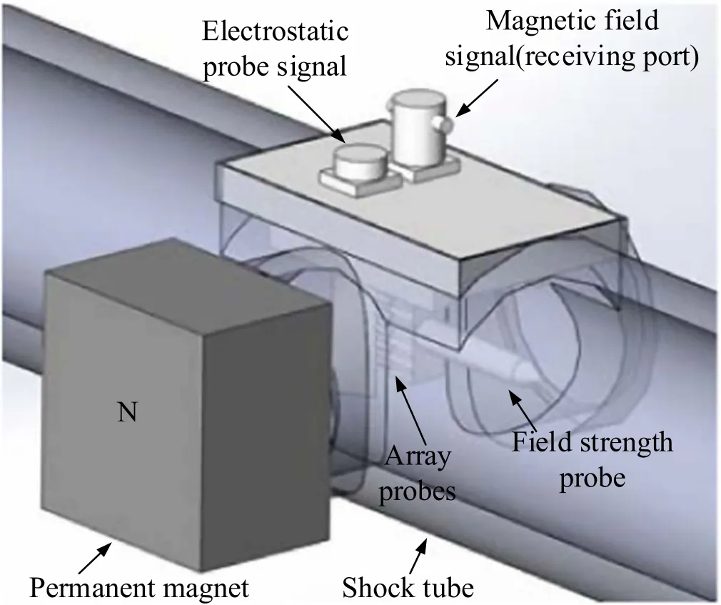
Figure 6.3D graphical representation of the experimental arrangement.
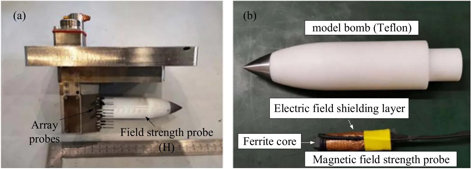
Figure 7.Photographs of array probes and field strength probe holder.
A piece of cubic Nd–Fe–B permanent magnet(45 mm×45 mm×80 mm)was mounted outside the shock tube at a distance of approximately 5 cm from the plasma.A static magnetic field distributed along thex-axis was applied in the experiment,and the magnetic field was perpendicular to the plasma flow(as shown in figure 6).The magnetic field strength of the permanent magnet was obtained using a Gauss meter.The intensity of the magnetic field acting on the magnetic field probe was approximately 0.06 T.
The detailed experiment process is shown in[3,4].In the experiment,we measurednearound the magnetic field probe using high-resolution array probes.The array electrostatic probe diagnosis system adopted the static-electricity triple-probe diagnostic method.The system had three scanning channels.When the shock front reached the trigger point,the ionization probe generated a signal that triggered the three sets of probes around the model to measure simultaneously.The magnetic field acting on the probe was weak,the ion saturation current was basically unaffected by the magnetic field,and we thus used the same diagnostic method in the experiment of applying the magnetic field.The collision frequency is estimated as in[31].wherePis the neutral gas pressure(atm)andTeis the electron temperature(K).
The interaction of LF EM waves with high-electrondensity plasma will cause severe attenuation;if the static magnetic field is applied at this moment,then the value ofSHwill vary.Adopting identical parameters,the records of the two experiments with and without applying an external static magnetic field are compared,revealing the effect of the static magnetic field on the propagation characteristics ofSH.
4.2.Effect of a non-uniform static magnetic field on SH
On the basis of the experimental configuration,we obtain the distribution of the external static magnetic field in the cylindrical enveloping plasma through numerical simulation,for which the corresponding three-dimensional model is shown in figure 8(a).The model parameters are set as follows.The outer and inner diameters of the shock tube are 6 and 4 cm,respectively.The dimensions of the cubic permanent magnet are 45 mm×45 mm×80 mm.
The simulation results shown in figure 8(b)reveal that the strength of the static magnetic field distributed along the direction of thex-axis is dominant at the transmission window,and that the magnetic field intensity steeply decreases with increasing distance between the field point and permanent magnet.
We consider the four magnetic field points shown in figure 8(b).The magnetic field strengths areB1=B4=0.30 T andB2=B3=0.03 T,which are close to the test values in the experiment.According to equation(22),we obtainSHunder the effect of a non-uniform magnetic field.The results forSHatf=10 MHz andf=30 MHz are compared in table 2.Throughout the experiment,the distribution of the static magnetic field approximates to being non-uniform,indicating the suitability of the analytical solution of non-uniform magnetized plasma in comparison with the experimental results.

Figure 8.The distribution of magnetic field in space.(a)3D simulation model,(b)external static magnetic field at x–y plan within the vacuum chamber.
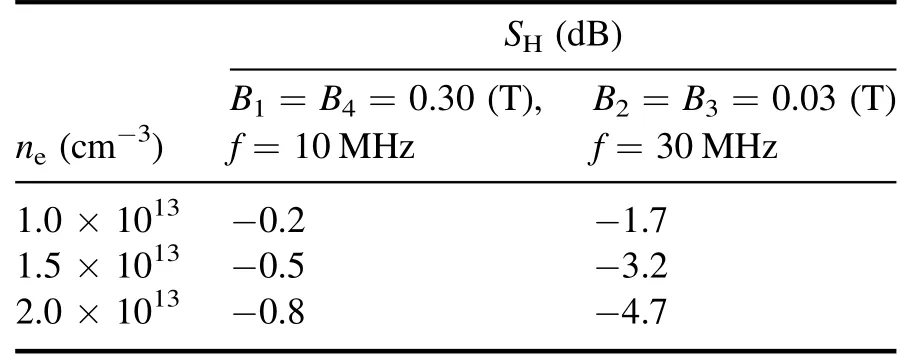
Table 2. SH under the influence of non-uniform magnetic field.
4.3.Experimental results
Figure 9(presenting raw data in the time domain measured by the oscilloscope)and figure 10(presenting the amplitude results obtained from the raw data in the time domain)respectively show the experimental results ofSHforf=10 MHz andf=30 MHz with and without a magnetic field.In figure 9(a),there is appreciable attenuation of the magnetic field signal in the plasma to which no external static magnetic field is applied.In figure 9(b),under conditions of the similar plasma experiment environment,SHis greatly reduced by applying an external magnetic field(the magnetic field strengthB0acting on the magnetic field probe was about 0.06 T).
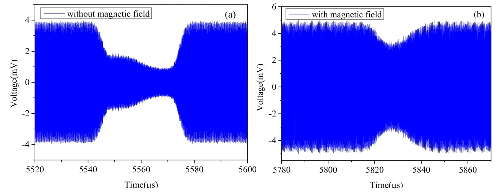
Figure 9.Raw measurement data in time-domain for f=30 MHz.(a)Without magnetic field,(b)with magnetic field.
Figure 10 shows amplitude results with and without the static magnetic field when adopting synchronous demodulation to process the raw data in the time domain.The electron density in the figure 10 is the average value measured before and after applying the magnetic field.The principle and detailed process of synchronous demodulation were discussed in[4].Comparing the experimental results in terms of different frequencies,we find thatSHatf=30 MHz is much higher than that atf=10 MHz,suggesting that the phenomenon of blackout is more inclined to occur at higher electron density when increasing the frequency of the LF EM waves.After applying the external static magnetic field,SHmeasured under the static magnetic field is reduced.The experimental results show thatSHatf=10 MHz reduced to 3 dB(i.e.a reduction of 82.9%).Furthermore,f shows that the same effect is achieved at higher frequencies.After applying an external magnetic field,the maximum reduction ofSHatf=30 MHz in the plasma reaches approximately 10 dB(i.e.74.3%)during the experiment.

Figure 10.Comparison of experimental results with and without the magnetic field for LF EM waves.(a) f=10 MHz,(b) f=30 MHz.
Figure 11 shows that the results of simulation using the analytical expressions ofSHatf=10 MHz andf=30 MHz are close to those of the experiment.Comparing with the results obtained using the analytical expressions of non-uniform magnetized plasma,we discover that the analytical simulation results ofSHunder a static magnetic field are also reduced.
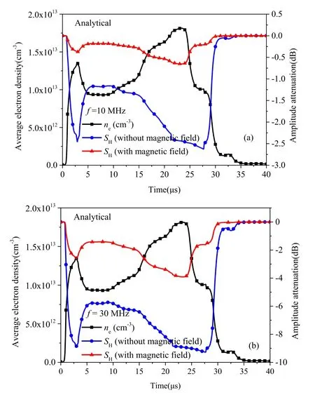
Figure 11.Comparison of analytical results with and without the magnetic field for LF EM waves.(a) f=10 MHz,(b) f=30 MHz.
The comparison of analytical solutions with experimental results forSHunder the effect of a non-uniform magnetic field is shown in figure 12.It is seen that the experimental results are similar to the analytical solutions.This not only verifies the accuracy of the equivalent circuit approach of the analytical expressions,but also validates the effectiveness of the applied magnetic field in terms of reducingSH.

Figure 12.Comparison of analytical solutions with experimental results for SH under the influence of non-uniform magnetic field.(a)f=10 MHz,(b) f=30 MHz.
5.Discussion
A transverse magnetic field was applied in the experiment reported in this paper,and the results of the experiment suggest that the application of a static magnetic field reducesSH.In practical applications,the external magnetic field is usually applied under the antenna,that is,a longitudinal magnetic field is adopted.The analysis shows that applying a longitudinal magnetic field and applying a transverse magnetic field have the same promoting effects,thereby demonstrating the potential feasibility of the proposed magnetic window method for reducingSHof LF EM waves in engineering applications.
6.Conclusions
The new effect of LF EM wave transmission in plasma was combined with the static magnetic window.In the static magnetic field,free electrons on the plane perpendicular to the magnetic field lines are frozen on the magnetic field lines.The resulting increase in the plasma equivalent resistance reduces the induced current and thusSH.In this method,the static magnetic field acting on the plasma of the entire induced current loop is considered.Adopting an equivalent circuit,an analytical expression ofSHpropagating in magnetized cylindrical enveloping plasma was derived to describe the effect of the static magnetic field onSH.The effect of the magnetic field on LF EM waves propagating in the cylindrical enveloping plasma was also studied in an experiment.The results indicate thatSHdecreases under a magnetic field.Specifically,the maximum reduction ofSHin shock plasma(ne≈1.9×1013cm−3,ve≈6 GHz)approximates 3 dB(about 83%)and 10 dB(about 74%)under the applied magnetic field(the magnetic field strengthB0acting on the magnetic field probe was about 0.06 T)withf=10 MHz andf=30 MHz respectively,suggesting that the magnetic window has greater potential in terms of increasing the tolerance of the electron density ofSHfor LF EM waves.
Taking −30 dB as the threshold for radio blackout,the LF EM waves withf=10 MHz andf=30 MHz encounter communication blackout at an altitude of 56 km for plasma in the experimental results of RAM-C[32].It may be a viable option to use a static magnetic field to mitigate the radio blackout of LF EM waves.Furthermore,for identical plasma properties,information can be transmitted at carrier frequencies higher thanf=3 MHz(i.e.the previously expected EM wave frequency[2])under a static magnetic field,whereby the amount of information being transmitted is expected to be enormous.
Acknowledgments
This work was supported by National Natural Science Foundation of China(Nos.61771370,and 11704296).The authors thankfully acknowledge the help from Hypervelocity Aerodynamics Institute,China Aerodynamics Research and Development Center.
ORCID iDs
猜你喜欢
杂志排行

Plasma Science and Technology的其它文章
- Numerical simulation of carbon arc discharge for graphene synthesis without catalyst
- Enhanced removal of ultrafine particles from kerosene combustion using a dielectric barrier discharge reactor packed with porous alumina balls
- Visualization of gold nanoparticles formation in DC plasma-liquid systems
- Rice plant growth and yield:foliar application of plasma activated water
- An active tunable Fano switch in a plasmafilled superlattice array
- Comparison of sample temperature effect on femtosecond and nanosecond laser-induced breakdown spectroscopy