Application of Gaussian beam pre-stack depth migration in rugged seabed
2021-05-26HANFuxingYIXinSUNZhangqingHUJiaXUBaoyinandXUHai
HAN Fuxing, YI Xin, SUN Zhangqing*, HU Jia, XU Baoyin and XU Hai
1. College for Geo-Exploration Science Technology, Jilin University, Changchun 130026, China;2. Geophysical Exploration and Research Institute of Jilin Oilfield, Songyuan 138006, Jilin, China;3. Overseas Center of Sinopec Petroleum Exploration and Development Research Institute, Beijing 100083, China
Abstract: Strong fluctuation of seabed, abrupt variation in depth and dip of seabed bring seismic imaging problems, such as irregular reflection waves, obvious multiple waves, serious lateral wave development, poor imaging on base surface and depression structure, low signal-to-noise ratio of middle and deep layers. In this paper, Gaussian beam migration imaging method is used to analyze the imaging effect of rugged seabed in deep water area, and the ray tracing method of wavefront construction method is used to analyze the kinematic characteristics of seismic waves. By improving the design of seismic data acquisition and observation system, imaging quality of fine structures is improved.
Keywords: Gaussian beam migration; wavefront construction method; Gaussian beam; pre-stack depth; rugged seabed
0 Introduction
At present, with the rapid development of global economy, the international demand for oil and natural gas energy is increasing, and the onshore oil and gas resources are decreasing day by day, so the offshore oil exploration is becoming more and more important. With the advancing of exploration and development, the exploration target is gradually moving towards deep water and deep layer, transiting from the conventional structural trap to the lithologic trap. The subtle, dense and complex carbonate and buried hill reservoirs have gradually become the focus of oil and gas exploration in various sea areas in China (Zhangetal., 2006). Oil and gas exploration and development are facing more and more complex geological problems, so it is necessary to improve the ability of seismic data processing and interpretation.
Because of the significant increase of water depth, sharp changes of geological dip angle in deep sea area, the energy transmission of seismic wave field is greatly affected, which leads to the decline of seismic data imaging quality (Yeetal., 2016). In seismic data, there are many phenomena, such as disordered reflection wave, obvious multiple wave, serious lateral wave development, poor base surface imaging, poor depression structure imaging, low signal-to-noise ratio in middle and deep layers (Hanetal., 2017). Therefore, it is necessary to carry out in-depth research on the imaging of rugged seabed topography. In terms of acquisition parameters of deep-water seismic exploration, Luoetal. (2009) and Zhang (2015) conducted theoretical calculation and obtained some acquisition parameters. Liuetal. (2013) established the initial velocity model based on constrained velocity inversion combined with fault control, using percentage scanning velocity analysis to iteratively modify the original velocity model, and then realized the convergence of velocity volume with high efficiency. Lietal. (2010) and Wen (2011) focused on the energy distribution characteristics of seismic wave illumination, studied the transmission and propagation of wave field on the seabed exploration area by using the forward modeling method of Gaussian ray beam, as well as the characterization of seismic wave energy intensity and dispersion collected by geophone. Dengetal. (2015) adopted the combined multiple attenuation technology and multi domain noise suppression technology to improve the signal-to-noise ratio and resolution of the data, so as to significantly improve the data quality. Lietal. (2017) based on the diffraction multiple attenuation technology (GCDMA) constrained by geostatistics, realizes the determination and attenuation of residual diffraction multiples through the statistics and modeling decomposition of geological signals. Xuetal. (2019) proposed relevant processing methods: using combination suppression multiple to solve the problem of attenuation of multiple attenuation in rugged sea bottom, so as to present the deep structure; using predictive deconvolution and zero phase processing technology were used to improve the resolution of shallow hydrate; using multiple iterative velocity analysis technology to gradually refine the velocity analysis accuracy and highlight the velocity inversion related to hydrate features. Lietal. (2020) proposed a multiple prediction technique based on the continuation of one way and two-way wave equations. From the wave equation, combined with SRME technology, the wave field of seismic data is extended by using rock physical model and the preset multiple model is obtained. At the same time, the effect of complex sea floor multiples is suppressed by using mutual contrast and difference. Finally, on migration imaging, Chen and Ge (2005) analyzed the original time migration, post stack depth migration and pre-stack depth migration methods to verify the practicability of seismic exploration imaging in complex deep water area by using the principle model of his own creation. Finally, through the analysis and comparison of the corresponding migration imaging profiles of different seawater models, it is concluded that both the original time migration method and the post stack depth migration method can not present the migration profile of marine seismic well, but the pre-stack depth migration can achieve the best imaging effect. Sun (2016) used Kirchhoff pre-stack depth migration and reverse time migration to conduct pre-stack depth migration imaging of deep-water rugged seabed.
At present, migration methods can be divided into four directions: Kirchhoff, One way wave equation migration, Reverse time migration and beam migration. Kirchhoff integral method assumes that the wave propagates in a relatively smooth medium, so the velocity field should be relatively smooth. Moreover, when the lateral velocity of subsurface medium changes suddenly, the Kirchhoff migration method under the assumption of high-frequency gradual change will have some problems in imaging, such as serious caustics, multipath and so on, which is not suitable for rugged seabed. One way wave migration method can be applied to complex geological bodies, but it is difficult to image steep dips. The main reason is that the method is derived from the one way solution of two way wave equation, and paraxial approximation is needed when solving one way wave equation by numerical difference method. That is to say, when the one way wave propagates downward near the vertical stratum, the amplitude of seismic wave will be weakened and the phase will be changed in the process of propagation of the seabed with steep dip angle, which is unfavorable to the imaging of rugged seabed with steep dip. Reverse time migration is named after wave field continuation based on reverse time sequence, followed by imaging with calculated wave field. The wave propagation is relatively complete in the reverse time migration algorithm, which is not limited by the steep dip angle problem. However, the reverse time migration requires a large amount of calculation and storage, and is sensitive to the velocity error, so it is difficult to be applied to anisotropic media and large data set processing. To sum up, there are some limitations and disadvantages in the above-mentioned three methods for very deep water areas. Compared with the conventional ray method, Gaussian beam can provide a smoother first-order asymptotic solution of the wave equation. In addition, the Gaussian beam avoids the failure of the standard ray theory in the caustic region through the complex amplitude. Gaussian beam migration method not only has higher imaging accuracy than other methods, but also inherits many advantages of conventional Kirchhoff migration, which is convenient and practical for irregular observation system. At the same time, it can effectively process multiple first arrivals and accurately image complex areas such as caustics and shadow areas. To sum up, this paper uses Gaussian beam migration imaging method to analyze the imaging effect under the rugged seabed conditions in deep water area. The workflow starts with introducing the principle of Gaussian beam migration imaging, and then the ray tracing method of wave front construction method is used to analyze the kinematic characteristics of seismic wave in deep water area. Finally, a calculation example is given to illustrate the actual effect of the method, so as to put forward the proposal for the processing of subsea seismic data for exploration in deep water area.
1 Gaussian beam migration imaging
1.1 principle of Gaussian beam migration imaging
The calculation process of Gaussian beam pre-stack migration is to get the Green function of the source and the receiver at the imaging point through the Gaussian beam, then the Green function obtained from the receiver and the seismic records are decomposed to obtain the upstream wave field, and the Green function obtained from the source point is used to obtain the downward wave field. Finally, the imaging results are obtained by cross-correlation between the uplink wave field and the downlink wave field.
Firstly, in isotropic media, the source is set asxs=(xs,ys). The receiver isxr=(xr,yr). Then the seismic wave fieldu(x,xs,ω) of the reverse continuation at x on the ground(Yue, 2011). Using Rayleigh Ⅱ integral formula, it is expressed as follows:
(1)
Using the superposition integral of Gaussian beamUGB(x,xr,p,ω), the three-dimensional green’s functionG(x,xr,x,ω) from the receiver pointxrto the calculated pointxis as follows:
(2)

exp{-iωpr·(xr-L)}
(3)
The above formula is the core of the Gaussian beam migration method proposed by Hill (1990).
According to the extension integral, Clayton and Stolt (1981), Hildebrand and Carroll (1993), expressed the pre-stack imaging formula as follows:
(4)
WhereIpre(x) is the final pre-stack imaging value. The Green’s function in (4) is represented by Gaussian beam integral:
(5)
The Formula (5) is applicable to shot point or receiving point domain, and to center point and offset by coordinate transformation. However, if Gaussian beam emitted from the center of the beam is used to approximate the Green’s function of the receiver, the computational cost can be reduced. Using the above simplified method in different regions, the Gaussian beam migration expressions of different gathers can be obtained.
The principle diagram of common shot area Gaussian beam migration is shown in Fig. 1.
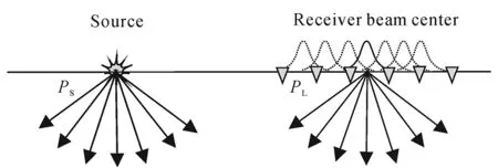
Fig.1 Principle diagram of Gaussian beam migration for common shot set
Firstly, it is necessary to determine the beam center positionLrof some receiving points
(6)
Then, using Formula (2) to express the source Green functionG(x,xs,ω), and using Equation (3) to express the Green functionG(x,xr,ω) of the receiver point near the beam centerLr, then:
(7)
Simplify the above formula as the final Gaussian beam offset formula in the common shot point domain.
The simplified formula is
(8)
1.2 Calculation example
In order to analyze the calculation accuracy of the above methods, the Gaussian beam method is applied to some actual velocity models for migration imaging calculation, and the differences between the original velocity model and the migration results are compared. The velocity models used in this paper are smoothed 20 times before using.
(1) Horizontal seabed model
The seabed velocity model as shown in Fig. 2a is adopted. The size of the velocity model is 3 200×3 000, and the grid spacing is 2 m×2 m. the shot points are located from (100, 4) to (3 100, 4), with a total of 33 shots with a shot spacing of 200 m. Each shot has 640 channels received, the channel spacing is 10 m, and the sampling interval is 4 ms. The forward modeling is obtained by using the 2d-8-order finite difference program.
According to the migration imaging results in Fig. 2b, it can be seen that the Gaussian beam migration method is in good agreement with the seabed velocity model.

(a) Deep water model; (b)migration section of its corresponding model. Fig.2 Deep sea bottom velocity model (a) and migration profile (b)
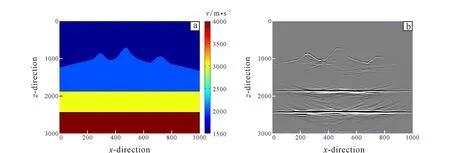
Fig.3 Submarine volcanic velocity model (a) and its migration profile (b)
(2) Volcanic model
The seabed velocity model shown in Fig. 3a is used. The size of the model is 1 000×800, and the grid spacing is 4 m×4 m. The shot points are located from (100, 2) to (900, 2), and the shot spacing is 400 m. There are nine shots in total. Each shot has 160 channels received, the channel spacing is 20 m, and the sampling interval is 2 ms.
According to the migration imaging results in Fig.3b, it can be seen that Gaussian beam migration can image volcanoes. However, due to the obvious fluctuation of volcanoes, we find that when the slope of the seabed and the strata below the seabed is very steep, the reflected wave will propagate to a very far position, that is, the reflected wave of the reflection point in the exploration area can only receive the signal beyond a large offset range. To solve this problem, and in order to obtain clear image of the undulating interface, the wave field within the effective width near the ray will be simulated according to the ray tracing algorithm, and the kinematic characteristics of complex seabed seismic wave will be analyzed, so as to improve the design of seismic data acquisition and observation system to improve the fine structure imaging. Compared with other ray tracing algorithms, the wavefront construction method has many advantages, such as being able to adapt to more complex velocity model and realize the full coverage of the research area. Therefore, wave front construction method is used in this paper to analyze and process the wave field characteristics.
1.3 Ray theory solution of wavefront construction method
The wavefront construction method is mainly composed of two sets of equations: one is kinematic ray tracing equations; the other is dynamic ray tracing equations. Kinematic ray tracing uses Fermat principle and Huygens principle to obtain the travel time and path along the central ray, and then uses the information obtained by ray tracing to obtain the effective seismic wave field information around the central ray. (Han, 2009)
Based on the calculation of seismic travel time and ray path, the ray propagation path of seismic wave field energy is simulated by using the ray tracing method of wavefront construction, and then the influence of steep slope on seismic wave field energy transmission is analyzed. Based on the above-mentioned volcanic model, the positions of shot points are changed in turn, and the energy transmission path is analyzed by ray tracing.
2 Application examples
2.1 Submarine volcano model
As can be seen from the velocity model in Fig. 4, due to the existence of large dip angle and undulating seabed trend in deep water area, most of the energy cannot penetrate the stratum, and only a small part of energy can penetrate into the lower middle and deep layers of the formation. At the steep dip angle, no matter how to change the initial position of the shot point, some energy will propagate along the boundary of the exploration area to a very far place, so that it can not be received in this acquisition mode.
The seismic wave energy analysis of the missing part of submarine volcanic structure shows that most of the energy can be received from the shot point (1 400, 2) to (1 600, 2), as shown in Fig. 5.
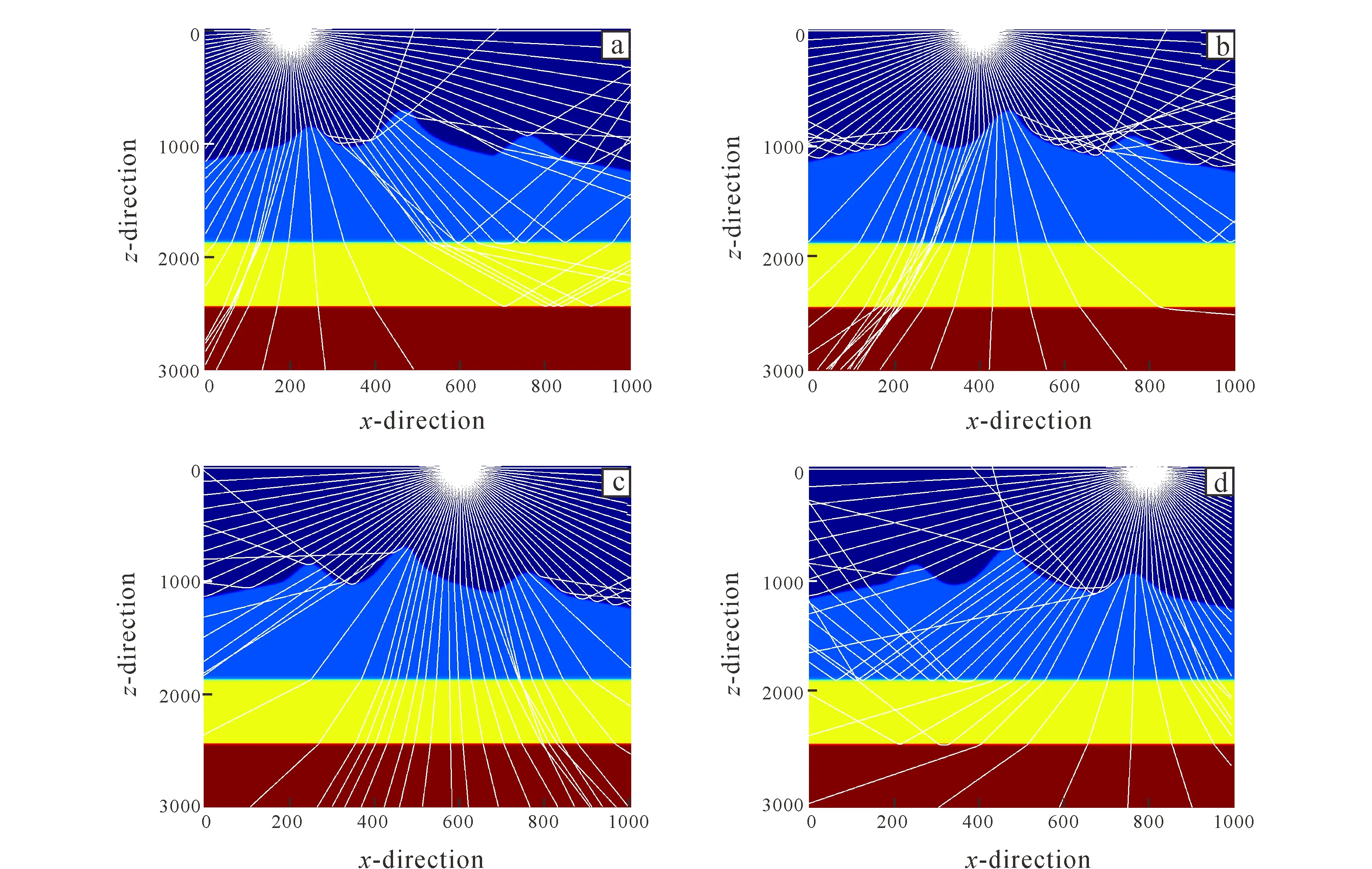
Shot point position: (a) x=200; (b) x=400; (c) x=600; (d) x=800.Fig.4 Distribution of seismic ray paths of submarine volcanoes at different focal locations
By modifying the acquisition system and adding the detection points on the right side of the exploration area, the seismic wave energy of the missing part of the structure can be received.
According to Fig. 6, the imaging quality of submarine volcanic structure can be improved by increasing the length of acquisition array and improving the observation system, so that the migration profile can be well consistent with the velocity model.

Shot point position: (a) x=600; (b) x=800.Fig.5 Seismic ray path distribution of submarine volcanoes at the same source location and different geophone location

Fig.6 Comparison of submarine volcanic migration profiles before (a) and after (b) modification of observing system
2.2 Complex and rugged seabed model
On the basis of the seabed level in Fig. 2, the model is modified to make the undulating surface of the seabed change dramatically, as shown in Fig. 7a.
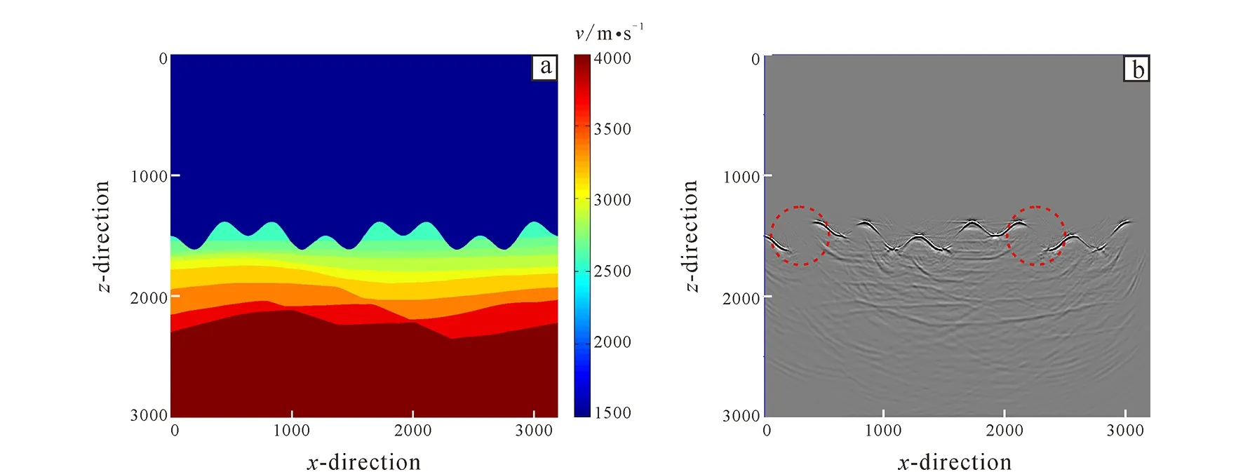
(a) Deep water model; (b) migration section of the corresponding model.Fig.7 Velocity model and migration profile of complex (a) and rugged seabed (b)
According to the imaging results of migration profile in Fig. 7b, it can be seen that the Gaussian beam migration method has a good agreement with the seabed velocity model, but there is still a structural missing part at the high dip angle position under the condition of large steep slope and complex seabed. Therefore, this paper still uses the ray tracing theory to modify the acquisition system and add the shot point and detection point setting corresponding to the missing part of the structure to supplement the complete system.
The distribution of seismic ray paths on rugged seabed after changing the source location is shown in Fig. 8.

Shot point position: (a) x=500; (b) x=1000; (c) x=1500; (d) x=2000; (e) x=2500; (f) x=3000.Fig.8 Seismic ray path distribution of rugged seabed at different source locations
The seismic wave energy analysis is carried out for the missing part of the rugged seabed structure with large dip angle, as shown in Fig. 9.
By modifying the acquisition system and supplementing the shot point, the seismic wave energy can be transmitted to the missing part of the structure to strengthen the seismic data signal.
As shown in Fig. 10, the offset profile of Fig. 11b can be obtained by supplementing the shot points on both sides of 1 km of the surveyed area and improving the energy supplement at the structural missing position.

Fig.9 Ray path distribution of seismic wave in structure missing part
Through the comparison between the migration sections in Fig. 11, it is found that the missing structure can be completely presented on the migration profile, achieving the expected migration effect.
Through the above analysis, it can be seen that the Gaussian beam algorithm has good calculation accuracy, and its migration profile can be well consistent with the velocity model. Meanwhile, it is found that the observation system needs to be further improved for the rugged seabed with steep dip angle. For example, the acquisition array length can be increased by analyzing the wave field of ray, calculating the wave travel time and ray path, which can improve the imaging quality of complex seabed structure.

Fig.10 Ray path distribution of supplementary shot points
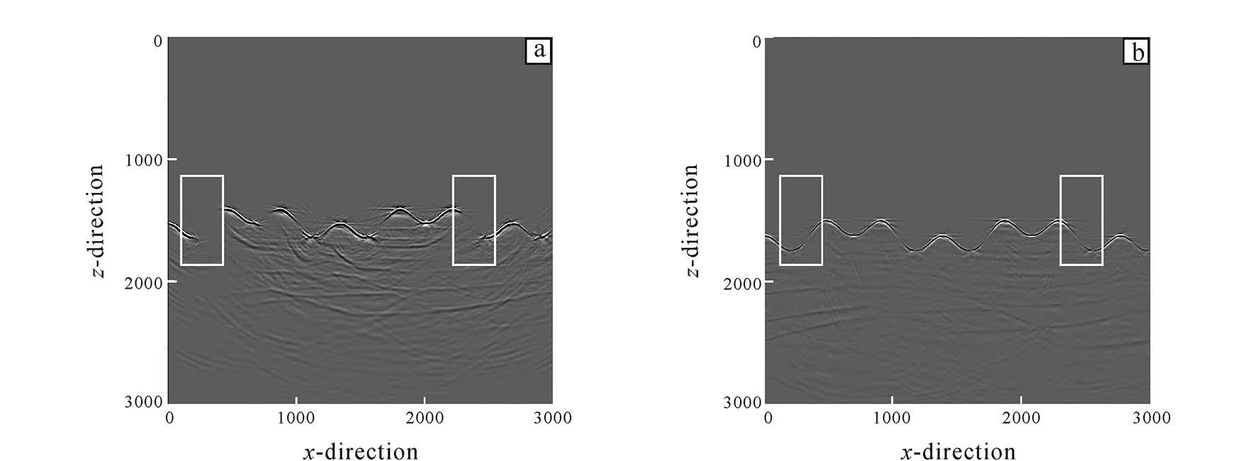
Fig.11 Migration profile of rugged seafloor after modification of observation system
3 Conclusion
By comparing the velocity model with the migration imaging results, it can be found that the Gaussian beam pre-stack depth migration method is in good agreement with the seabed velocity model, but there is still a structural missing at the position of large dip angle under the condition of steep and complex seabed.
To solve this problem, ray tracing algorithm can be used to simulate the wave field in the effective range near the ray to analyze the kinematic characteristics of seismic waves in the rugged seabed of deep water. By improving the design of seismic data acquisition and observation system, i.e., to add the shot point and detection point corresponding to the missing part of the structure, the system can be supplemented to improve the imaging of all the fine structures.
杂志排行
Global Geology的其它文章
- Influence of fracture width on borehole radar response
- Common offset ground penetrating radar data inversion based on ray theory
- Evolution characteristics of hydrological connectivity pattern of marsh wetland in Naoli River Basin
- Geochemical characteristics and sedimentary environment significance of carbonate rocks in Nanfen Formation of Qingbaikou System in Tonghua, Jilin Province
- Origin of ore-forming fluids in Qinggouzi stibnite deposit,NE China: Constraints from fluid inclusions and H-O-S isotopes
- Chemical indexes of Paleoproterozoic sedimentary rocks from Liaohe Group, North China Craton: Implications for paleoclimate and provenance
