Progress in twin roll casting of magnesium alloys: A review
2021-05-21AmjadJavaidFrankCzerwinski
Amjad Javaid, Frank Czerwinski
CanmetMATERIALS, Natural Resources Canada, Hamilton, Ontario, L8P 0A5, Canada
Received 15 June 2020; received in revised form 29 September 2020; accepted 10 October 2020
Available online 4 December 2020
Abstract
Keywords: Twin roll casting; Magnesium alloys; Solidification Magnesium sheet.
1. Introduction
Casting is the dominant manufacturing process of netshape components, representing about 98% of overall structural applications of magnesium. Its industrial dominance is fueled by two major factors, where firs one is the excellent castability of magnesium alloys, which exceeds other metals such as aluminum or copper and is caused by its unique solidificatio features including high fluidit and low susceptibility to hydrogen porosity. The second one is the inherently poor formability of magnesium at room temperature, caused by its hexagonal lattice structure [1],[2].
The low formability represents the key obstacle in the progress of industrial scale rolling of magnesium. It limits the magnesium application expansion since a sheet is the essential form of semi-finishe products, which is commonly used in forming procedures for production of net-shape parts[3],[4]. The conventional manufacturing of magnesium sheet consists multistep processes including melting, ingot casting,homogenization, milling, multiply heating, hot rolling, cold rolling, and fina annealing [5],[6]. To address this challenge,the search is on for a new technology of sheet manufacturing and novel magnesium alloys that feature improved formability.
Twin roll continuous casting (TRC), also known as twin roll strip casting, is seen as the technique that may overcome barriers of magnesium formability and allow manufacturing sheet or strip products directly from a molten state. The technology takes advantage of best features of both fundamental processes: casting and rolling since it combines them into a single-step operation, thus reducing the manufacturing cycle time,energy consumptions,pollutant emissions and fina cost,compared to traditional sheet production using a direct chill ingot casting. It is claimed that investment costs of TRC are 1/3 to 1/4 of level required for conventional sheet production[7],[8]. At the same time, however, the TRC process provides some limitations.
This report describes global activities aimed at expanding capabilities of TRC to manufacture strips of magnesium alloys, emphasizing the progress made in development of this technology.
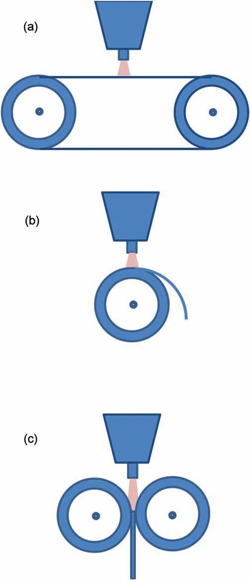
Fig. 1. Design examples of strip casters: (a) belt caster; (b) single roll caster;(c) twin roll caster.
2. History of TRC and its application for Mg alloys
Direct strip casting is a continuous casting technique for producing metallic sheet directly from the molten state that minimises the need for substantial secondary processing[9],[10]. Among many concepts of direct strip casting a particular place is devoted to TRC [9]. As shown in Fig. 1a, Belt Casters (BC’s) use water cooled travelling molds or conveyor belts.Another modificatio is a Single Roll Caster(SRC)used to produce thin-gage strip (Fig. 1b). The third group covers Twin Roll Casters, where various configuration are available(Fig. 1c). Development of the TRC process took more than 100 years and now it is used for strip production from both ferrous and non-ferrous alloys including steel [11],[12],[13],nickel[14],titanium[15],aluminum[16],[17],zinc[18],copper [19],[20] and magnesium.

Fig. 2. A schematic of Bessemer’s continuous casting machine. Reprinted from Ref. [10].
2.1. Concept and early modifications
The original idea of manufacturing metallic products through continuous casting is linked to the US patent by Laing in 1843 on continuous casting of tubes and sheets [21]. Based on an existing strip caster, made for producing tin foils and lead strips, Bessemer patented in 1865-67 a TRC caster design for iron and steel strips [22],[23] (Fig. 2). The progress was, however, hindered by three major technical difficultie of the design; liquid metal feeding, edge containment, and strip quality [24]. An important milestone was the successful production of the 3-5mm thick steel strip by Norton in 1890[25].
The development of strip casting technology for light metals was pioneered by Hunter and Pechiney who became leaders in designing the twin roll casters for aluminum. The firs commercialized twin-roll caster for aluminum alloys, the Hunter Standard Caster, was introduced in 1954 by Hunter,using the upward-vertical twin-roll design [26]. It was followed by development of the world’s firs horizontal twin-roll aluminum caster,the Harvey Caster,in 1962 by Pechiney.The new horizontal twin-roll caster with a 15deg upward tilt was introduced by Hunter in 1970s.
2.2. Application to magnesium alloys
Historically, magnesium twin-roll casting has benefite from aluminum heritage [27]. The firs attempts of an application of TRC to magnesium were made by Dow Chemical Company in the early 1980s by using a Hunter horizontal caster, originally designed for aluminum, combined with the proprietary feeding system,developed for handling molten magnesium [28]. The global interest in TRC of magnesium sheet increased rapidly in early 2000 with worldwide activities to develop technology of manufacturing magnesium sheet

Table 1 Modification of twin roll caster applicable to magnesium alloys [29].
2.3. Asymmetric twin roll casting
To improve mechanical properties of the strip, a direct influenc on the strip formation conditions during twin-roll casting can be explored. Asymmetric rolling is a technique used to control both the texture and the grain refinemen of metallic materials. There are beneficia effects of asymmetric rolling, conducted by applying a high ratio of the circumferential velocities between the upper and lower rolls. In analogy to rolling, additional shear stresses may be created in the strip forming zone by using different circumferential velocities and torques of the caster rolls. According to Ref. [30], to provide the asymmetric process conditions during TRC, only one caster roll may be left driven and the second one may be left idling during the casting process. The literature data show a positive influenc of the asymmetry conditions on the magnesium strip properties [31]. Unless indicated otherwise,all data in this report refer to symmetric twin roll casting.
2.4. Process challenges unique to magnesium
Decades of research showed that an application of TRC to magnesium strip production has proven difficul with several main challenges, being unique for magnesium alloys:
1. High affinit of magnesium to oxygen, causing that molten metal readily oxidizes and ignites without good protective atmosphere systems and control [32],[33]. This requires a development of safe but simple protection for molten magnesium that is crucial for achieving high-quality sheet and preventing defect formation. There are areas, where melt cannot be protected by cover gas, e.g. during transfer between metal delivery system components. The reaction with oxygen affects strip surface quality and content of oxide-related inclusions inside the strip.
2. High solidificatio rate due to lower specifi heat and latent heat of fusion causes molten Mg to freeze faster than Al alloys.
3. Magnesium alloys have larger freezing ranges than aluminum wrought alloys, which may result in formation of cracking and segregation defects in as-cast strip [34].
4. Low formability of magnesium alloys, especially at room temperatures as compared to aluminum alloys [35],[36].
5. High corrosivity of molten magnesium alloys and their reaction with machine components affects the performance of hardware being in contact with the melt, e.g. reactivity between the nozzle material and liquid magnesium alloys,control of nozzle temperature and a material selection to minimize the corrosive reaction, which leads to melt contamination [32].
3. Strip formation during TRC

Fig. 3. Schematic of strip formation during horizontal twin roll casting with geometrical details of the liquid-solid zones within the roll gap.
Two major phenomena: solidificatio and deformation affect the strip development during TRC with the former having the dominant effect. As the melt cools down the rolls exert pressure affecting its deformation before and after complete solidificatio (Fig. 3). The solid state thickness reduction reaches about 5-20%. The high solidificatio rate of the strip leads to refinin its microstructure, improving chemical homogeneity and weakening the crystallographic texture.
3.1. Macro- and microstructure
The manufacturing process directly affects the macro- and microstructure of the strip. As the major contributing factor, a difference in solidificatio conditions across the strip thickness is seen. The strip solidificatio starts from a contact surface with the rolls and progresses simultaneously from both top and bottom towards the strip center. This leads to formation of three zones in the strip cross section: surface chill zone, central equiaxed zone and dendritic columnar zone(Fig. 4). There is no distinct boundary between individual zones with a transient being gradual and influence by processing parameters and alloy chemistry. Because of dynamic recrystallization taking place during hot deformation within the chill zone the fin grains are formed. The constitutional undercooling contributes to formation of equiaxed grains in the strip center. A microstructure of the AZ31 strip cross section with dimensions of individual zones and transient between them is shown in Fig. 5.
There is a consensus that high solidificatio rates experienced during TRC and ranging from 102to 103°C/s,have positive effects on the strip microstructure and resultant properties: homogeneous microstructures with fin grains,especially minimizing the size of manganese-rich compounds,reduced chemical segregation, increased solid solubility and enhanced precipitate nucleation within the matrix [37].Moreover, features of microstructure modifications related to rapid solidification positively affect the strip formability at room temperature [38].
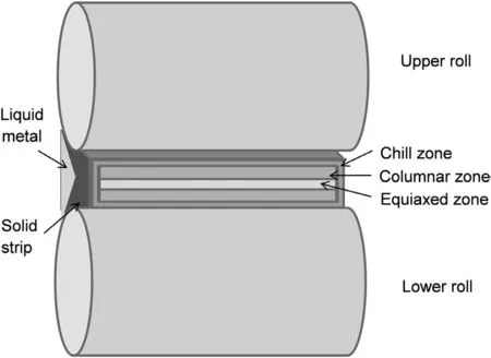
Fig. 4. Schematic explaining formation of solidificatio zones with different microstructure within the strip during TRC.
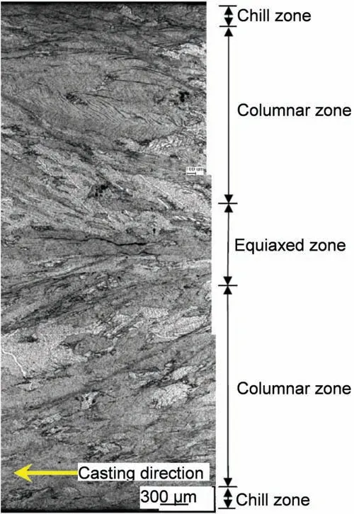
Fig. 5. Cross-sectional microstructure of the TRC strip with 2000mm width and 5.9mm thickness (AZ31 alloy). Reprinted from Ref. [40].
As a result of deformation exerted by the rolls, the strip grains in near-surface regions are elongated along the rolling direction.This feature is seen during microscopic observations in the rolling plane. For two strip thicknesses of 2.5mm and 6mm for the AZ31 alloy, no evident differences in average grain size were reported [39].
The asymmetric twin-roll casting was found to produce inhomogeneous microstructure along thickness of the AZ31 strip [31]. There were many banded structures, which form near the upper surface of the strip, whereas a fin dendritic structure dominated near the lower surface of the strip. It was concluded that the shear strain, caused by the difference in linear velocity between the surfaces of the upper and lower rolls, resulted in the banded structures of the strip.
3.2. Chemical segregation
An advantage of strip casting is the refinemen of intermetallic compounds, which otherwise exist as harmful coarse particles in conventionally processed alloys. The fin and homogeneously dispersed particles retard the motion of dislocations, increasing strength and at the same time blocking dislocations so they change the slip systems by cross-slip to maintain good ductility. Moreover, the fin particles inhibit the grain growth during high temperature heat treatment.However, common defects of TRC strip include the inverse and centreline segregations.
3.2.1. Inverse segregation
The inverse segregation is seen as inherent problem of TRC strip, being closely correlated with solidificatio mechanism during a dynamic scenario of strip development. The inverse segregation is exactly opposite to that expected when the low melting fraction, solidifying as the last one, is in the strip center [40]. During TRC process, the inverse segregation occurs on both outer surfaces where solidificatio begins. The feature is generated when the remaining highly solute-enriched liquid, accumulated between already solidifie columnar zones, is squeezed out through the weak intercolumnar layer from the center region towards the strip surface due to the compressive force of casting rolls (Fig. 6).
The inverse segregation is affected by alloy chemistry,casting speed, melt temperature, roll separation force, roll gap,setback distance and by magnesium oxidation and melt cleanness. The factors detrimentally affecting inverse segregation are a large amount of remaining liquid at low temperature,wide solidificatio range and the volume of secondary phase during TRC process. A high contribution of the secondary phase may increase the roll force and induce defects during warm rolling. Since the precipitation of secondary phase at low temperatures during fina heat treatment is beneficia for increasing strength a compromise in alloy chemistry is required. According to Ref. [41], a reduction of central segregation in the 5mm thick and 250mm wide AZ31 strip led to elimination of inverse segregation. In turn, a change in the strip microstructure, which consisted of equiaxed dendrites,contributed to elimination of inverse segregation in Mg-4Zn-X-Ca alloys [42].
3.2.2. Center-line segregation

Fig. 6. Formation schematic of inverse segregation during TRC: (top) trapping of liquid phase into central region, and (bottom) transfer of entrapped liquid phase from center to top and bottom strip surfaces under pressure from rolls. Reprinted from Ref. [40].
In addition to inverse segregation the common defect reported in TRC strip is center line segregation. This phenomenon is related to mechanism of strip formation where two solidificatio fronts are joined together. Since center line segregation represents in fact 3D feature its observation on fla polished section may lead to incorrect conclusions. It is postulated that a three-dimensional approach should be applied in order to understand the solidificatio process and liquid fl w during strip formation. It was shown for the TRC of 5.6mm thick strip of the AZ31 alloy that a three-dimensional image of the volume containing center line segregation cannot be obtained using conventional metallographic methods, whereas X-ray micro tomography allows the complete reconstruction of its major features [43].
According to the two-dimensional finit element thermalfluid-stres model of the thermomechanical response of the AZ31 alloy during twin roll casting the key parameter for center line segregation is the mushy zone thickness [44]. For inverse segregation, the interaction between the peak stress at the center line in the mushy zone and the solidifie shell on the roll surface is the key parameter.
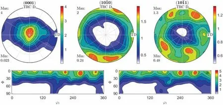
Fig. 7. Texture of 5.3mm thick strip of Mg-2Zn-1Al-0.3Ca alloy after TRC showing measured (0001) basal, (10-10) prismatic and (10-11) pyramidal pole figure and calculated Orientation Distribution Functions (ODF) for φ2= 0° and φ2= 30°. Reprinted from Ref. [56].
In case of Al alloys, elimination of edge cracks and centerline segregation of twin-roll cast strip was proposed by ultrasonic melt treatment. As a result of the acoustic streaming and micro-jets brought by ultrasonic, the liquid fl wing in the sump was motivated, which further promoted the solute redistribution, suppressing the centerline segregation [45]. Another technique positively tested on Al alloys involves forced cooling. When the forced-cooling technology was applied in the twin-roll casting process of the AA6022 aluminum alloy, by virtue of changing of crystallization front depth and crystallization front shape, the segregation defects were suppressed[46].It is anticipated that these solutions will apply to magnesium alloys as well. Experiments with the AZ31 magnesium alloy showed that intensive shearing melt conditioning prior to twin roll casting eliminated the severe centerline segregation, resulting in a refined uniform, and nearly equiaxed microstructure [47]. It is assumed that the microstructural homogeneity was achieved through enhancing the heterogeneous nucleation during solidification
3.3. Extension of solute solubility limit
An extension of solid solubility of chemical elements in magnesium by rapid solidificatio is well established [47].The rapid solidificatio during TRC leads to non-equilibrium effects, including extension of solid solubility and formation of metastable phases. The higher solidificatio rate increases occurrence of these phenomena [48]. For magnesium TRC,in addition to refinemen of intermetallic compounds an expansion of solid solubility in the strip was reported [28]. The latter phenomenon enables better utilization of alloying elements that have limited solid solubility in magnesium, such as transition metals,for improving mechanical properties.It is reported that rapid solidificatio can effectively extend solid solubility in magnesium, for example 1.5 times for MgAg and about 1000 times for Mg-Ba alloys [49]. The combination of solid solution hardening with grain refinemen makes rapid solidificatio during TRC a suitable technique for enhancing the mechanical properties and corrosion resistance of Mg alloys.
3.4. Development of crystallographic texture
Since during TRC, there is a contribution of deformation due to rolling, one would expect a preferred orientation of grains within the strip. Solidificatio with its directional progress, leading to columnar grains oriented towards the strip center, may have some contribution, as well. However, the magnitude of deformation after strip solidificatio is the major factor. It should be emphasized that formation of strong crystallographic texture during magnesium rolling is seen as the key negative factor of magnesium formability[1]. For Mg-Al-Mn alloys the twin-roll cast sheets developed weaker basal intensity texture than the ingot-cast sheets [50].
3.4.1. Effect of TRC process on strip texture
According to predominant portion of literature results,twin roll casting leads to formation of a weakly-pronounced basal texture. The isolated data report the strong texture within the TRC manufactured strip.
Experiments with TRC of the AZ31 alloy showed a weak texture, formed by basal planes aligned in the strip plane.Measurements revealed the (0001) and (10-10) pole figure with maximum intensities of Imax=2.2 and Imax=2.1, respectively, indicating a close to random texture [51],[52]. Since solidificatio during TRC is directional, deformation imposed by the rolls occurs preferentially near the strip surface and is adjacent to grain boundaries. A weak texture was also measured for TRC strip of AZ31 in Ref.[53].The texture resulted in low anisotropy of strip properties with tensile yield stress reaching 220MPa along the TRC direction and 190MPa in a direction perpendicular to the TRC direction. Similar effects were observed for more complex alloys [54].
A lack of strong texture was also reported after EBSD analysis of the surface and interior of TRC strip of the AZX611 alloy [55]. The strip did not show any specifi grain orientation in either the surface or interior, regardless of the grain size. The maximum texture strength reported of 3.8 times random is higher than in other studies. Also, twin roll casting of the Mg-2Zn-1Al-0.3Ca alloy resulted in formation of a weak basal texture, characterized by a slight asymmetric tilting of the basal plane [56]. There was a preferential orientation of the prismatic and pyramidal planes in regards to the TRC direction (Fig. 7).
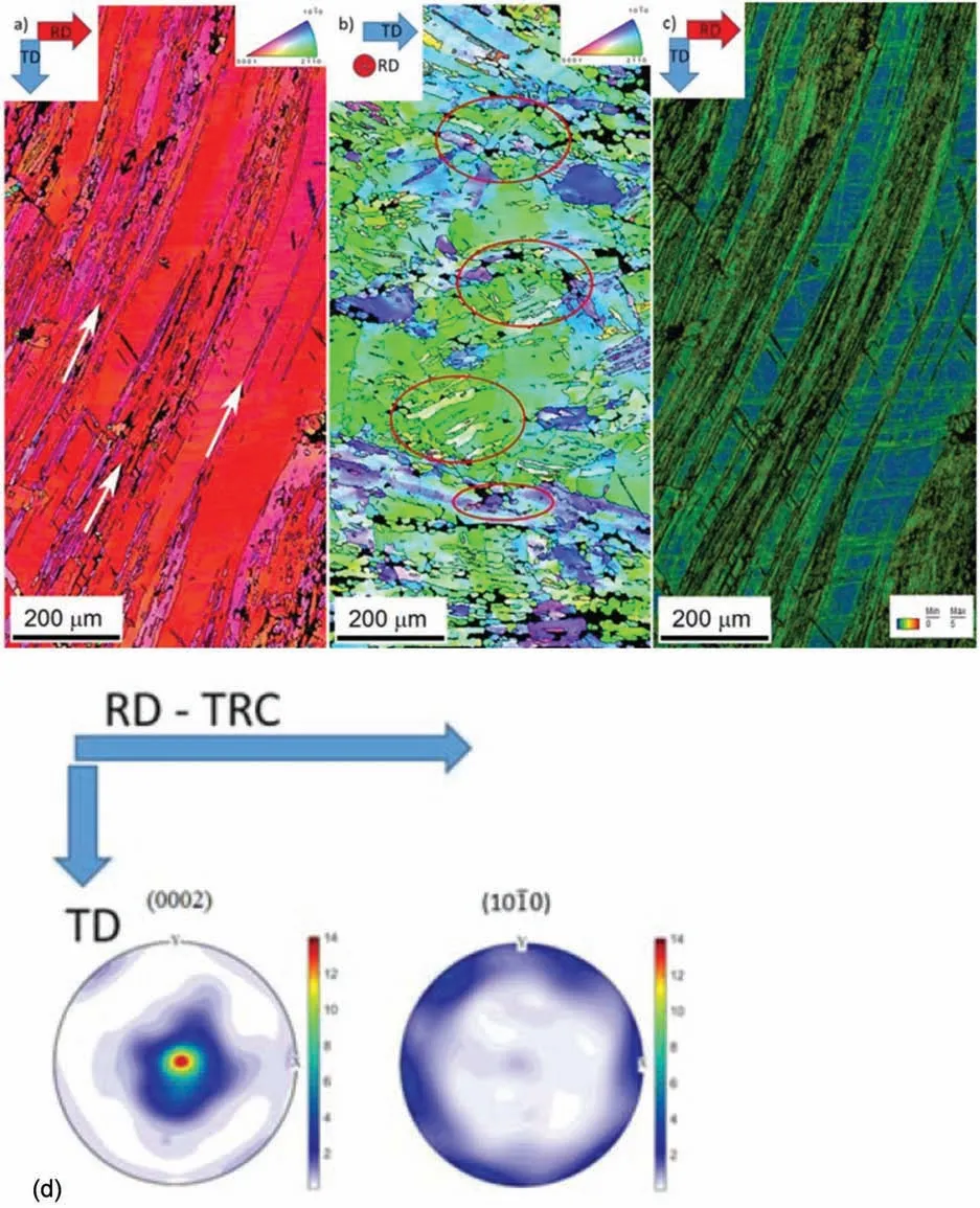
Fig. 8. Texture of the ZEK100 alloy (Mg-1Zn-0.3Zr-0.3Nd) strip with thickness of 4mm after twin roll casting: (a) orientation image map of the strip surface with white arrows indicating the fine-graine strips; (b) strip cross section; (c) basal and pyramidal pole figure measured in orientations indicated. Reprinted from Ref. [57].
In contrast to above reports, experiments with twin roll casting of the ZEK100 alloy (Mg-1Zn-0.3Zr-0.3Nd), assessed by neutron diffraction, revealed a strong basal texture, formed during the TRC process with a slight off basal character towards both RD and TD directions [57]. According to measured pole figures the basal texture strength reached maximum of 14 times random (Fig. 8). Although a higher work hardening was observed in the rolling direction due to the more intensive dislocation activity, the difference in mechanical properties of the strip deformed in the RD and TD directions was rather small. This findin contradicts, however, the widely accumulated evidence that a presence of rare earths in magnesium alloys, in particular Nd, weakens the basal deformation texture [58-60].
3.4.2. Texture inhomogeneity across the strip thickness
At the firs approximation, no obvious influenc of strip thickness on surface texture measured after TRC are distinguished. For example, for the AZ31 alloy strip with a thicknesses of 2.5mm and 6mm, the crystallographic texture was similar in terms of type and intensity, being dominated by the basal component with a small fraction of the prismatic one[39].
At closer look, however, there is an inhomogeneity of texture across the strip thickness, related to differences in deformation and microstructure. As revealed for the AZ31B strip,the (0002) basal texture developed in the sub-surface region,and (1 0 -1 4) texture was measured in the strip center [61].Detailed measurements found that the sub-surface region exhibited a simple (0 0 0 2) [1 1 2 0] basal texture. The strip center developed more complex texture with(1 0-1 4)plane,oriented at an angle of 25.1deg to the basal plane,being parallel to the rolling plane and [1 0 -1 0] direction being parallel to the rolling direction.
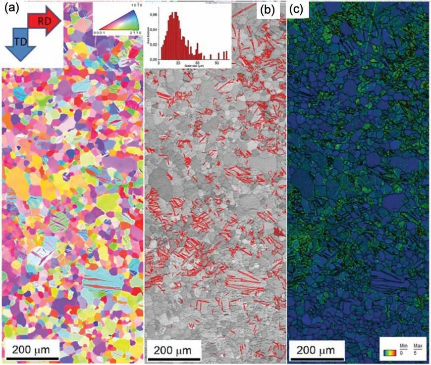
Fig. 9. Orientation image map (OIM) of the ZEK100, 4mm thick TRC strip after annealing at 413°C for 24 h: (a) showing recrystallization; (b) twin boundaries (marked in red color) and the grains size distribution shown in inset; (c) Kernel average misorientation map [57].
In Mg-Zn-Ca alloys, the distribution of basal poles was found to be orthotropic, which might result in anisotropy during deformation and have adverse effect on formability[63].It was explained that an enhanced tension twinning activity, believed to be due to a presence of Ca, modifie its microstructure such that the grains can deform along the thickness direction after twinning.
Another findin related the texture inhomogeneity to the grain size. For the AZ31 alloy the macro-texture analysis showed basal components when the micro-texture analysis by electron back scattered diffraction (EBSD) revealed that the large grains were mostly basal, however, the smaller grains tended to have varying orientations [62].
3.4.3. Effect of post-TRC treatment on strip texture
The texture developed during TRC can increase or reduce its intensity as a result of subsequent rolling or heat treatment.
3.4.3.1. Symmetric rolling. In order to manufacture a thin sheet from the TRC strip precursor, multi-pass rolling is typically required. Due to low room-temperature formability of magnesium, hot/warm rolling is preferred. In due course of rolling the weak texture of the TRC strip is transformed into strong basal texture of the rolled sheet [63]. Thus, hot rolling of Mg strip to reduce its thickness leads to development of a relatively strong basal texture, known to produce anisotropic tensile properties in different directions. For example, a weak texture of the ZK60 strip after TRC led to strong basal texture after additional hot rolling at 350°C [64].
3.4.3.2. Asymmetric (shear) rolling. Press formability is strongly affected by the texture and it can be improved by asymmetric rolling as a consequence of reduction of the basal texture intensity. In magnesium, the basal fibe texture is notably weakened during this form of rolling [65]. Several promising paths to improve shear rolled texture have been identified using preliminary experimental data and computational modeling [66]. The modificatio of deformation mode from thickness reduction to shear deformation can change the texture from (0002) basal one to other components, and shear deformation can substantially reduce the grain size [67]. According to texture measurements for the AZ31 sheet,produced from TRC strip,the maximum pole intensity values were 17.4 for commercially available 1mm thick sheet, 16.2 for commercial 2mm thick sheet and 10.1, for symmetrically rolled sheet. After asymmetric rolling, the texture strength of 9.5 was measured, indicating an improvement [68]. Thus, twin roll casting combined with shear rolling has the potential to decrease the cost of fabrication of magnesium components.

Fig. 10. Texture of 5.3mm thick TRC strip of Mg-2Zn-1Al-0.3Ca alloy after annealing at 420 °C for 2h shown through measured pole figure and calculated Orientation Distribution Functions for φ2= 0° and φ2= 30°. Pole figure taken from TRC D-TD plane. Reprinted from Ref. [56].
3.4.3.3. Heat treatment. As a part of microstructure rearrangement during heat treatment, weakening of TRC texture occurs. As shown in Fig. 9 the stored energy after TRC was sufficien to initiate recrystallization during subsequent heating. Since the static recrystallization is mostly controlled by the particle-stimulated nucleation mechanism, randomly oriented nuclei lead to a weaker recrystallization texture [57].The heat treatment following TRC results in a recrystallization and anisotropy of mechanical properties. As a result of the easier activation of twinning in TD given by texture, the yield stress in this direction reached only half of that in RD.The effect of heat treatment after TRC is seen in Fig. 10 for the Mg-2Zn-1Al-0.3Ca, wt.% alloy strip where stronger spreading of the basal poles towards TD from ND occurred[56]. At the same time, the prismatic and pyramidal planes exhibited a similar alignment with TD.
4. Magnesium alloys processed by TRC
The vast majority of research, pilot scale TRC tests, including commercial-scale manufacturing of Mg strip,involves the AZ31 alloy. Research with other commercial and experimental alloys is rather conducted at the laboratory scale. The strip made from high strength Mg alloys is rarely reported.A selection of tensile properties for TRC strips made from a variety of alloys is listed in Table 2.
4.1. AZ31 alloy
The research is mainly focussed on structure of the strip and its inhomogeneity [69],[40],[43],[44], surface segregation[41] or post-TRC processing [31]. The role of AZ31 melt temperature was emphasised in Ref. [70]: the strip developed dendrites when the superheat was high, and of a rosebushlike structure when the superheat was low. When the casting temperature was close to the liquidus temperature the as-cast microstructure became globular with a fin grain, positively affecting the strip formability.
There are reported attempts of chemistry modificatio of the AZ31 alloy through minor additions of other elements.Additions of 0.08 wt.% Ca into AZ31 melts, significantl reduced the average grain size within the TRC strip from 100μm to 30μm through formation of Al2Ca. Crystallographic examination of relationship between Al2Ca and Mg,revealed using the edge-to-edge matching model, indicated that Al2Ca particles are effective inoculants for heterogeneous nucleation of Mg [71].
4.2. Alloys with high Al contents
Although 3wt.% is the common Al level present in the AZ31 alloy, there are reported trials with TRC of Mg alloys with higher Al content reaching 9 wt.%,typical for cast alloys[72].
The Mg-4.5Al-1.0Zn (AZ41M) alloy sheets produced by twin roll casting, sequential warm rolling and annealing at 350°C showed higher strength and lower elongation after sequential warm rolling [73]. Annealing after warm rolling caused a reduction in strength and an increase in elongation.The grain refinemen was attributed to the formation of heavy shear bands, high dislocation density, twinning, and precipitates of Al2Ca/Mg2Ca or Al8Mn5and the Ca dissolution in the Mg17Al12phase.
TRC experiments with Mg-6Zn-1Mn (ZM61) alloys having varying Al contents showed microstructure refinemen with increasing Al and changes in a type of precipitates:from MgZn2in ZM61 alloy to Al8Mn5in the ZM61-1%Al (ZMA611) and ZM61-3% Al (ZMA613) alloys [74].The ZMA611 alloy showed better combination of tensile properties than the ZM61 alloy. However, the ZMA613 alloy developed poor ductility due to formation of coarse Mg12(Al,Zn)17phase.
For 6 wt.% of Al in the ZK60 alloy, a sheet with 0.65mm thickness was successfully fabricated by TRC and subsequent hot rolling [75],[76]. According to [77], the ZK60 alloy showed coarser and equiaxed grains with eutectics and intermetallic compounds distributed along grain boundaries or inside grains. For the ZK60 alloy, increasing in cooling rate resulted in thereduction of dendrite arm spacing, grain size and an improvement in mechanical properties [78]. For the same ZK60 alloy, TRC provided more homogeneous microstructure than die casting and after heat treatment, shear bands and twins were present [64].
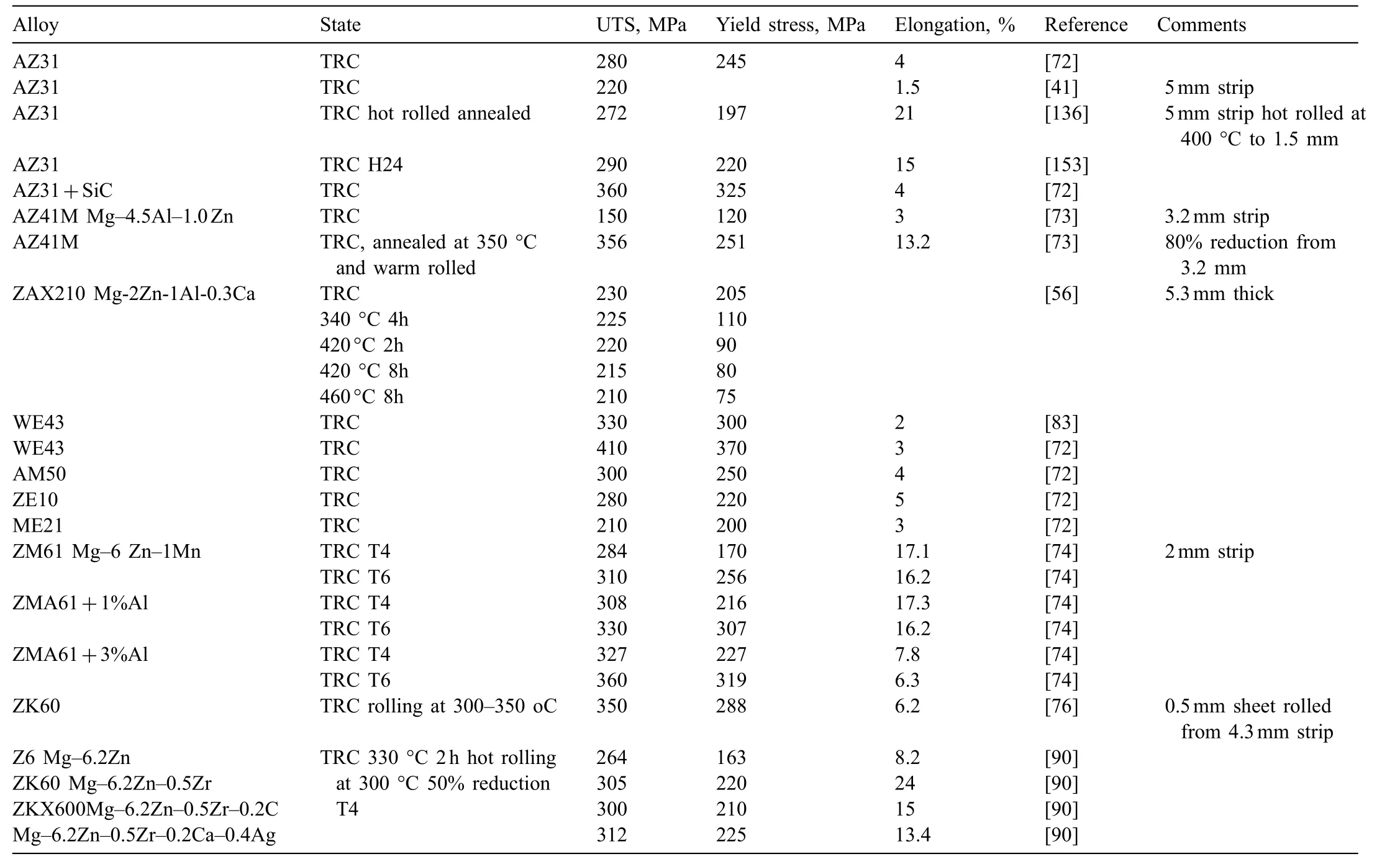
Table 2 Tensile properties of TRC strip and sheet of various magnesium alloys produced through TRC. Alloy compositions are in weight%.
There were successful TRC trials with 9 wt.% Al [79].For the AZ91 alloy, increasing in cooling rate increased the quantity of the solid-solution phase and a reduction in the fraction of Mg17Al12[80]. Besides the fine microstructure,TRC strips were also found to have lower segregation and more uniform distribution of grain size. In another trial, the AZ91 strip exhibited superplastic properties with elongation over 200%, when tested at 350°C and 1×10⁻³s-1strain rate[81]. As showed through experiments with horizontal twin roll caster in Ref. [82], high Al contents negatively affected formability of the strip. To verify effectiveness of twin roll casting of magnesium alloys with high aluminum contents,after hot rolling a warm deep drawing test was performed.As a result, limited drawing ratio of 2.4 was obtained in the warm deep-drawing test for AZ91 and 2.6 for AZ61, indicating rather low drawability.
4.3. Alloys with rare earths
TRC trials of Mg alloys with rare earths cover ZE10,ME21 and WE43 grades, which are known as high strength alloys with good corrosion behavior and creep properties[72].The strength of WE43 (4.04 wt.% Y, 2.59 wt.% Nd and 0.52 wt.% Zr) 315mm wide strip exceeded values reported for AZ31 with larger scatter of results, explained through higher microstructural inhomogeneity [83]. The key difference was in microstructure of the WE43 strip, which did not develop the typical dendritic structure like AZ- or AM-alloys. Instead, grains exhibited irregular, non-globular, partially serrated boundaries with β phase distributed between them. In another study, the WE43 alloy after TRC showed superplastic properties with elongations of over 400%, when tested at 450°C and 1×10⁻³s-1strain rate [81].
4.4. Experimental alloys
To improve performance during TRC and then strip properties the commercial grades are modifie with small additions of alloying elements or novel chemistries are developed.In addition to rare earths a particular interest is created by calcium. The clustering tendency of Ca promotes GP zone formation and evenly-distributed fin precipitates, including grain boundary regions [84].
4.4.1. AZ61, AZ31 with Ca, Sn
To address oxidation and ignition resistance the AZ31 and AZ61 alloys were modifie with additions of calcium [85].
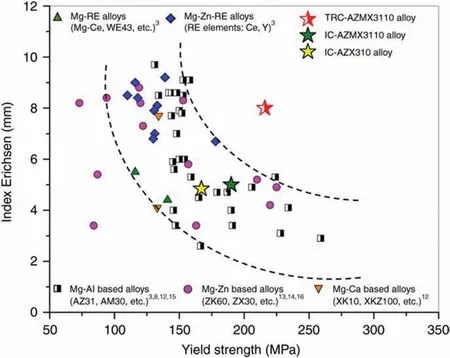
Fig. 11. Yield strength and stretch formability represented by the Index Erichsen (IE) value at room temperature of various Mg alloy sheets. The developed TRC-AZMX3110 alloy (Mg-3Al-1Zn-1Mn-0.5Ca) shows improved combination of strength and formability. Reprinted from Ref. [88].
As example, 1 and 2 wt.% of Ca were added to the AZ61 alloy to modify texture, microstructure, and mechanical properties of sheets produced by TRC and sequential warm rolling[55]. For alloys AZX610 (0.5 wt.% Ca), AZX611 (1.0 w.t%Ca) and AZX612 (2.0 wt.% Ca) the ignition resistance is emphasized with a claim of 1200°C limit for the AZX612 composition.
Another approach represents a modificatio of AZ31,where a small amount of Sn was added instead of Zn to improve a stretch formability [86]. A positive effect of 0.2 wt.%Ca to AM31 alloy on properties of TRC strip was reported in Ref. [87]. Among the Mg-4Zn-X-Ca alloys, the ZAX400(Mg-4Zn-0.3Al-0.3Mn-0.3Ca, wt.%) alloy exhibited a high yield strength value of 189.3MPa and excellent formability of 7.5mm with enhanced yield isotropy. The higher formability values of the Mg-4Zn-X-Ca alloys were closely related to the modifie deformation behaviors resulting from the texture evolution [42].
4.4.2. Mg-3Al-1Zn-1Mn-0.5Ca
The newly developed Mg-3Al-1Zn-1Mn-0.5Ca (wt.%) alloy marked as AZMX3110[88]shows a much improved combination of formability with the Index Erichsen (IE) value of 8mm and yield strength of 219MPa (Fig. 11). It was designed to utilize a beneficia effect of Zn/Ca co-segregation along grain boundaries on randomizing/weakening texture and to promote precipitation of intermetallic compounds, increasing strength. The AZMX3110 alloy suits TRC since the fast strip cooling leads to formation of fin Al8Mn5and Al2Ca particles. It should be mentioned that during conventional ingot casting of this alloy the Al8Mn5and Al2Ca particles were coarse, negatively affecting the properties.
4.4.3. Mg-6.1Zn-0.4Ag-0.2Ca-0.6Zr
The Mg-6.1Zn-0.4Ag-0.2Ca-0.6Zr(wt.%)alloy with a destination for TRC was developed through additions of 0.4 wt.%Ag and 0.2 wt.% Ca to the Mg-6.1Zn-0.6Zr grade [89]. The purpose of Ag and Ca micro-additions was to enhance the age hardening response after T6 heat treatment. After hot rolling of the 2mm thick TRC strip to 1.2mm and T6 heat treatment the alloy reached tensile yield strength of 320MPa and an elongation of 17%. Such processed sheet developed a weak basal texture and average grain size of 18±2.5μm. It is concluded that uniformly distributed fin rod-like MgZn2precipitates with a diameter of 5nm led to sheet strengthening.
4.4.4. Mg–Zn–Zr–Ca-Ag
Twin roll cast and hot rolled Z6 (Mg-6.2Zn wt.%) alloys containing Zr, Ca, and Ag as microalloying elements showed tensile yield strength exceeding 300MPa in the T6 (peakaged) condition with good formability in the T4 condition[90]. An addition of 0.5 wt.%Zr to Z6 alloy caused an increase of more than 50MPa in the tensile yield strength in the T4 condition with the property improvement attributed to grain refinemen and the spherical Mg(Zn,Zr) precipitates. An addition of 0.1 wt.%Ca to the ZK60 (Mg-6.2Zn-0.5Zr wt.%)alloy was sufficien for weakening the basal texture and increasing the formability even without a presence of expensive Ag. Thus, the low-cost Ag-free ZKX600 (Mg-6.2Zn-0.5Zr-0.2Ca wt.%) alloy is seen industrially promising as it exhibits equivalent mechanical properties to that of Agcontaining ZKQX6000 alloy (Mg-6.2Zn-0.5Zr-0.2Ca-0.4Ag wt.%).
5. Special applications of TRC
5.1. Amorphous magnesium sheet
Amorphization or crystallization can occur depending on cooling rates and thermal behavior experienced by the melt[91]. For a better understanding of the solidificatio behavior of TRC process, thermal fl w simulation was carried out with a conclusion that cooling rates during TRC create a possibility of formation of bulk metallic glasses [92],[93]. A similar conclusion was reached based on the simulation of structural transformations and comparison with CCT diagrams for certain magnesium alloys [94]. The results revealed that cooling rates above 103°C/s achieved during TRC are faster than the critical cooling rate calculated for the CCT diagram and sufficien to produce Mg-based metallic glasses.
Manufacturing of amorphous sheet with no surface defects from the Mg-29Cu-11Gd alloy is reported in. [95]. As a function of the roll speed, the structure of the as-cast sheet changed from being crystalline to fully amorphous and then back to crystalline. Through careful selection of the casting speed for the processed alloy chemistry the exit temperature of the sheet can remain within the super-cooled liquid region what leads to amorphous structure. The family of Mg-Zn-Al-RE (RE=Ce, Y, Pr) amorphous alloys produced by strip casting is provided in [96].
5.2. Mg matrix composites
The published reports on the Mg matrix composite strip are focussed on the continuous fibe reinforced structures and fabrication methods of multi-alloy laminar composites[97],[98],[99],[72].There is substantially more information on TRC of Al based composite strip and this knowledge is partly applicable to Mg [100].
The laboratory scale experiments portray success in manufacturing the TRC composite strip with the AZ31 alloy matrix and SiCpreinforcement particles [101]. In the process, the high shear technique was utilised to disperse the reinforcing particles uniformly into the matrix alloy before feeding the AZ31/5vol.% SiCpslurry into a horizontal twin roll caster.High cooling rate in the TRC process contributed to preserving the uniform distribution of SiCpparticles in the slurry,grain refinemen of the matrix with possible heterogeneous nucleation effect caused by reinforcing particles.
5.3. Mg cladding using TRC
The TRC technology is effectively used for cladding two distinct materials. Through exploring differences in melting ranges of two alloys, it allows manufacturing multi-functional lightweight alloy sheets having high formability, surface quality, and corrosion resistance as well as tensile and interfacial bonding properties [102]. There are efforts to manufacture various clad sheets, which can complement inherent features of Mg alloys. So far, research is focused on cladding Mg alloys with Al alloys.
Cladding after casting is often subjected to postmanufacturing treatments as homogenization, warm rolling,and annealing. As a result the interfacial layers are deformed into a saw tooth shape by forming deformation bands in the Mg alloy and interfacial layers,what leads to an improvement of interfacial bonding and tensile properties of the entire clad.
5.3.1. Cladding techniques
There are several examples how cladding concept can be executed through TRC. According to invention in Ref. [103],this is accomplished by feeding a thin sheet or foil at the point of contact between the roll and the core material, while the core is still in its molten state (Fig. 12). Due to the significan pressure of the rolls and solidificatio of the molten metal core, the resulting exit core is joined to the clad material. Ideally, the heat of the core metal would induce partial melting of the clad layer at the contact surface in order to create a strong metallic bond. The same technique was used for cladding Mg alloy with Al followed by annealing and rolling of the clad [104]. After TRC the reaction zone between Al and Mg contained Mg17Al12and ensured good bonding. Annealing of the clad sheet led to formation of Mg2Al3along the Mg/Al interface. An additional rolling of the as-annealed sheet reduced the thickness of the reaction zone and improved formability of the clad sheet.
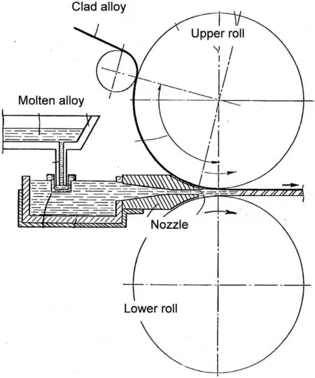
Fig. 12. A concept to clad Mg with Al alloy through feeding Al thin sheet during twin roll casting. Reprinted from Ref. [103].
Essentially the same concept is explored to clad molten Mg with multiply aluminum solid sheets, covering one or both sides of cast magnesium strip [105]. The twin roll cast magnesium sheet,clad on both sides with aluminum,provides the benefit of easier post-manufacturing treatment with less oxidation during rolling,reheating,annealing and forming operations. By repeating the cladding process, while using the clad product as a raw material during next step of TRC, multi layered structures can be manufactured by this method.
A different concept of manufacturing Al/Mg clad is proposed in Ref. [106]. As shown in Fig. 13, the technique explores a horizontal tandem twin roll caster and downward melt drag process along with in-line rolling [106]. First, the AZ121 alloy was cast by the firs twin roll and downward melt drag process was used for casting of AA1050 as the second strip. Due to narrow roll gap, AZ121 was melted by AA1050 through increased heat transfer between both materials.
5.3.2. Interfacial bonding
As a result of cladding a layered structure is developed with interfacial bonding, playing the essential role in properties of the entire aggregate. The cross section of the AZ31/Al clad (3.2mm/0.1mm) is shown in Fig. 14. After TRC and annealing at 300°C, two types of thin reaction layers with γ (Mg17Al12) and β (Mg2Al3) phases were formed along the Mg/Al interface [107]. The interface thickness depended on annealing time and measured 10.3μm and 19.9μm for 60min and 120min, respectively (Fig. 14a,b). The majority of Mg and Al grains were coarse, suggesting that 300°C was not sufficien to trigger recrystallization.
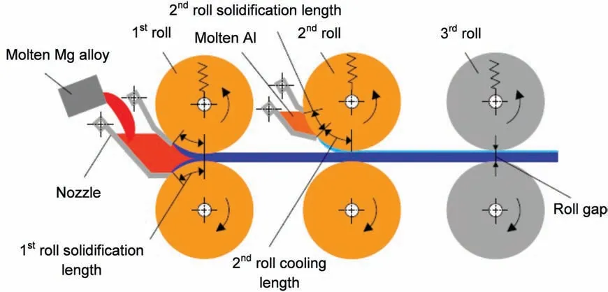
Fig. 13. Schematic illustration of cladding Mg with Al alloys in a horizontal tandem twin roll casting system. Reprinted with permission from Ref. [106].
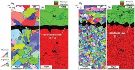
Fig. 14. Microstructure with EBSD inverse pole figure (IPF) and phase maps of AZ31/Al TRC clad: (a) as-cast and annealed at 300°C for 60min; (b)annealed at 300°C for 120min; (c) two-pass warm-rolled at 200°C with 36% reduction, plus annealed at 350°C for 10min in addition to (a); (d) two-pass warm-rolled at 200°C with 36% reduction, plus annealed at 350°C for 10min in addition to (b). Reprinted from Ref. [107].
The interfacial bonding is improved through post-TRC rolling. As shown in Fig. 14c,d the homogenized sheets were warm-rolled at 200°C with two passes to a reduction ratio of 36%, and annealed again at 350°C for 10min [107]. As a result the interfacial layers were deformed in a saw tooth shape by forming deformation bands in the Mg substrate and interfacial layers,while their thickness was retained.In some cases the interfacial layers were periodically broken to form large voids between broken layers.The Mg and Al grains are small,indicating recrystallization after the short-time annealing at 350°C.
6. Combining TRC with liquid metal engineering
The precise control of casting process parameters contributes to forming high quality casting strips. A reduction of overheating above liquidus leads to change from dendritic structures to rosette like morphologies [108]. Casting close to the liquidus temperature promotes formation of spherical or nodular primary α-Mg, which improves the strip workability.Benefi brings also feeding the twin rolls with fully molten alloy, subjected to physical treatment by external fields such as electrical, magnetic and acoustic [109],[110],[111].
6.1. Semisolid slurry
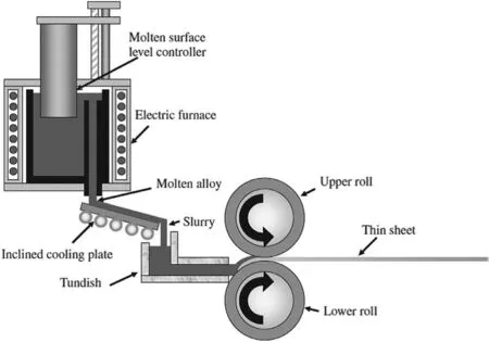
Fig. 15. Schematic illustration of a semisolid TRC using a cooling slope to generate thixotropic slurry. Reprinted with permission from Ref. [113].
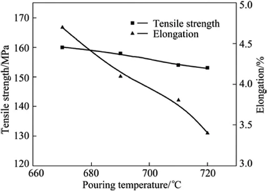
Fig. 16. Relationship between mechanical properties of strip and casting temperatures during TRC (vibration frequency 20Hz, roll speed 70mm/s).Reprinted with permission from Ref. [114].
After hardware modification the rolls of TRC machine can be fed with semisolid slurry instead of fully molten alloy. As a possible solution, cooling slope may be installed between melting pot and tundish [112] (Fig. 15). The molten metal solidifie quickly after leaving the casting tundish due to the contact with cooled rolls and is rolled during further transfer.In Ref.[112]magnesium alloys AZ31B,AZ91D,AM50A and AM60B were used for twin-roll strip casting using semisolid slurry. It has been found that 2.0-3.0mm thick magnesium strips could be produced at a speed of 25m/min. When using different speeds of upper and lower rolls, the grain size can be reduced to 10μm.
The cooling slope was also used to continuously cast the Mg-Al-Zn-Mn alloy into 2 to 3mm thick strip with a maximum width of 200mm[113].During semisolid processing the most important factors influencin sheet casting were casting temperature and twin-roll speed.
In another solution, a vibration system was installed along the slope plate to modify structure during formation of semisolid slurry before roll feeding [114]. During TRC of the Mg-3Sn-1Mn strip, increasing the roll speed led to higher solid fraction and grain size coarsening. Then, the size of primary solid particles, similarly as the alloy strength and elongation, decreased firs and then increased with increasing the vibration frequency. The overall conclusion is that a replacement of overheated liquid with semisolid slurry positively affects mechanical properties (Fig. 16).
The same concept as TRC, called semisolid continuous roll casting process (CRP), was used for strip manufacturing from the AZ91D alloy [115]. To generate semisolid slurry the damper cooling tube method was applied, which consists of fi e basic functional units: a pouring system, a cooling system, a heating system, a stirring system and a second temperature adjusting system. In Ref. [116], the term of rheocasting rolling is used for semisolid TRC. In this process semisolid AZ91D magnesium slurry was prepared by cooling slope and mechanical stirring. The optimum results were obtained for pouring temperature of 630 °C and casting temperature of 560 °C.
6.2. Molten alloy after physical treatment
The positive effects on strip quality are reported after feeding the TRC rolls with completely molten alloy subjected to physical treatment such as mixing, agitation, intensive shearing or twin screw conditioning[117],[110],[118].An intensive melt agitation caused a change in the solidificatio front during TRC, resulting in uniform distribution of grains throughout the strip thickness,significan reduction in center line segregation as a result of the smaller solidificatio front due to the fine microstructure [119]. The melt treatment allowed a reduction of the fina strip thickness, thus eliminating the extensive downstream processing via repetitive hot rolling,which is required after conventional twin roll casting to produce sheets to the thickness that is required for forming [39].
7. Numerical modeling of TRC
The computer simulation is an effective tool to investigate complex technological processes, especially when combined with experimental input and verificatio of the outcome.Computer modeling was extensively involved to simulate different elements of the TRC process and to design magnesium alloys that specificall suit this technique.
7.1. Process simulation
The literature provides examples from simple 2D models to complex simulations with individually created or commercial softwares. The computational flui dynamics (CFD) simulations were used to study the melt fl w and solidificatio phenomena occurring during TRC to control the strip quality, preventing surface and internal defects and building an optimized process-window [120]. As revealed by calculations the temperature of molten alloy decreases by 310 °C during contact with rolls, which suggests that the melt solidifie completely before leaving the kissing point (Fig. 17). There were also attempts to simulate a temperature distribution in a 1m long strip. In another approach the effect of type and dimension of melt delivery nozzles were analyzed by thermal fl w simulation [121].

Fig. 17. Temperature distribution within the solution domain and display of temperature differences between the roll surfaces shown in the diagram. The alignment of the two figure is done according to the examined roll boundaries. The diagram has the length of these boundaries. Reprinted from Ref. [127].
The CFD tool was also used to analyze different metal delivery systems to TRC rolls through modeling the heat conduction between magnesium and rolls [122],[123]. Similar aspects of cooling and solidificatio of the AZ31 sheet in horizontal TRC were studied by 2D numerical analysis [124]. As a result, the optimum process schedule was proposed for production of the 1mm thick sheet, where the sheet thickness decreased from 3mm through transition operations.
The geometry of the molten metal pool, the continuity of metal and the balance of energy and momentum were modeled based on analysis of the solidificatio phenomenon[125].In the process, fi e critical partial equations, including the equations of pool level, solidificatio process, roll separating force, roll gap and casting speed, were separately established.To obtain a uniform sheet thickness and keep a constant roll separating force, a decoupling control model was built on the perturbation method to eliminate the interference of individual processing parameters. The simulation proved that the control model is capable to quickly and accurately determine the control parameters.
In order to predict a velocity, temperature distributions of field and a solidificatio process of molten magnesium through analysis of the two-dimensional unsteady conservation equations for transport phenomena in the pool region of TRC, a special computer program has been developed [126].The energy equation of cooling roll was solved simultaneously with the conservation equations of molten magnesium in order to consider the heat transfer through the cooling roll.The program was used to examine the quantitative relationships of the roll speed, height of pool region, exit size of the nozzle, solidificatio profil and the fina point of solidifica tion in the strip
The commercial CFD software Star-CCM+ was used to create the TRC model based on an incompressible, steadystate solver for laminar fl w to study the heat transfer and solidificatio processes in horizontal twin-roll casting of the AZ31 alloy [127]. To describe the alloy solidification an exponential increase in viscosity at decreasing temperature was explored in addition to the fraction of solid approach based on a linear equation for the release of latent heat. In contrast to some studies of just a half of the domain under assumption of full symmetry, the full domain was analyzed. This approach revealed the asymmetric velocity profile of TRC, resulting in asymmetric temperature profile and thus temperature differences between the two rolls. Hence, symmetric results should not be enforced by using only half domain as the asymmetric profile create recirculation zones differing in size which might influenc the solidificatio rate (Fig. 18).
An interesting 2D analysis by the rigid-viscoplastic finite element method compared behavior of AZ31 and AA3003 alloys during vertical TRC [128]. In order for the surface of the sheet to solidify to avoid rupture, the roll speed was found to be lower than 0.3rad/s for AA3003 and 0.6rad/s for Mg-AZ31. For both materials, a reduction in rolling speed increased plastic deformation of the strip. A reduction of rollseparating force and the roll torque accompanied the increase in roll speed. The faster cooling rate of magnesium alloy translates to higher process efficien y than in case of aluminum alloy.
7.2. Modeling of post-TRC processes
There are examples of numerical analysis to figur out conditions of further processing of TRC strip into thin sheet.For example, dynamic modeling of TRC AZ41 (Mg-4.51Al-1.19Zn-0.5Mn-0.5Ca, wt.%) strip during hot compression processing was used to characterize the deformation behavior and microstructure evolution to describe the relations among fl w stress, strain, strain rates and deformation temperatures[129]. The fl w softening occurred at high temperature and low strain rate and the power-law behavior was followed.According to modeling, the stress hardening behavior played a main role at low temperature and high strain rate whilst the power law breaks down at this range. Meanwhile, the fl w stress curve turns into a steady state at high temperature and lower strain rate. As a result, temperature of 350°C and strain rate of 0.01 s-1were found optimum for this alloy.
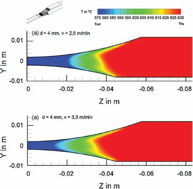
Fig. 18. Simulation of solidificatio interval (‘mushy zone’) of the melt with d=4mm (a) at v=2.5m/min and (b) v=3.3m/min. Reprinted with permission from Ref. [120].
7.3. Use of simulation to design alloys for TRC
A computer modeling is explored to design Mg alloys for TRC. In this attempt, the FactSage thermodynamic software with FTlite database was used for the thermodynamic calculation to predict the alloy tendency to form the inverse segregation within the strip [130]. The newly developed kinetic solidificatio model was also used to calculate the solidifi cation behavior at high cooling rates, typical for TRC. The prediction of as-cast microstructure was developed based on non-equilibrium Scheil cooling calculations. In parallel, the equilibrium calculations were performed to evaluate the heat treatment condition for homogenization (300°C ~450°C)and fina annealing process (150°C ~200°C) for secondary phase precipitation.
During the numerical analysis, all possible conventional alloying elements for Mg alloys were classifie as primary or secondary alloying elements based on their solubility limit in magnesium matrix. Then, the combinations of primary and secondary alloying elements were tested to fin the optimum composition, which can have similar or less inverse segregation tendency as the AZ31 alloy, have similar or low roll force, but have a large precipitation hardening during fina heat treatment. Several modification of Mg-Al and Mg-Sn based alloys were designed as possible candidates.

Fig. 19. Computer simulation of alloy design for TRC: (a) Scheil’s cooling calculation and (b) equilibrium calculation for Mg-3Sn-1Al-0.3Mn alloy.Reprinted from Ref. [130].
The thermodynamic and Scheil cooling calculations for the composition of Mg-3Sn-lAl-0.3Mn is shown in Fig. 19.During the Scheil solidificatio the amount of liquid remaining between growing columnar dendrites in the proposed alloy is smaller than that for the conventional AZ31 grade.As a result, there is a lower tendency to inverse segregation.At temperature range between 350°C to 500°C the volume of Al6Mn phase in the proposed alloy is almost the same as in AZ31. Assuming the similar work hardening by Al and Sn in magnesium matrix, it suggests that the rolling behavior of new alloy would be similar to that of AZ31. A heat treatment below 300°C, following TRC, can produce a large amount of the fin Mg2Sn phase, increasing significantl the alloy strength.
8. Global R&D facilities
In the early 2000s, research groups around the world, in particular in Korea, Germany, Japan, Turkey, Australia, and China started manufacturing the magnesium strip by TRCnot only at a laboratory but also at industrial pilot scale[28],[131].At present,many research institutes and companies compete to develop a technology for fabricating magnesium alloy sheet through the TRC route. The major R&D facilities, involved in development of magnesium TRC, are listed in Table 3.
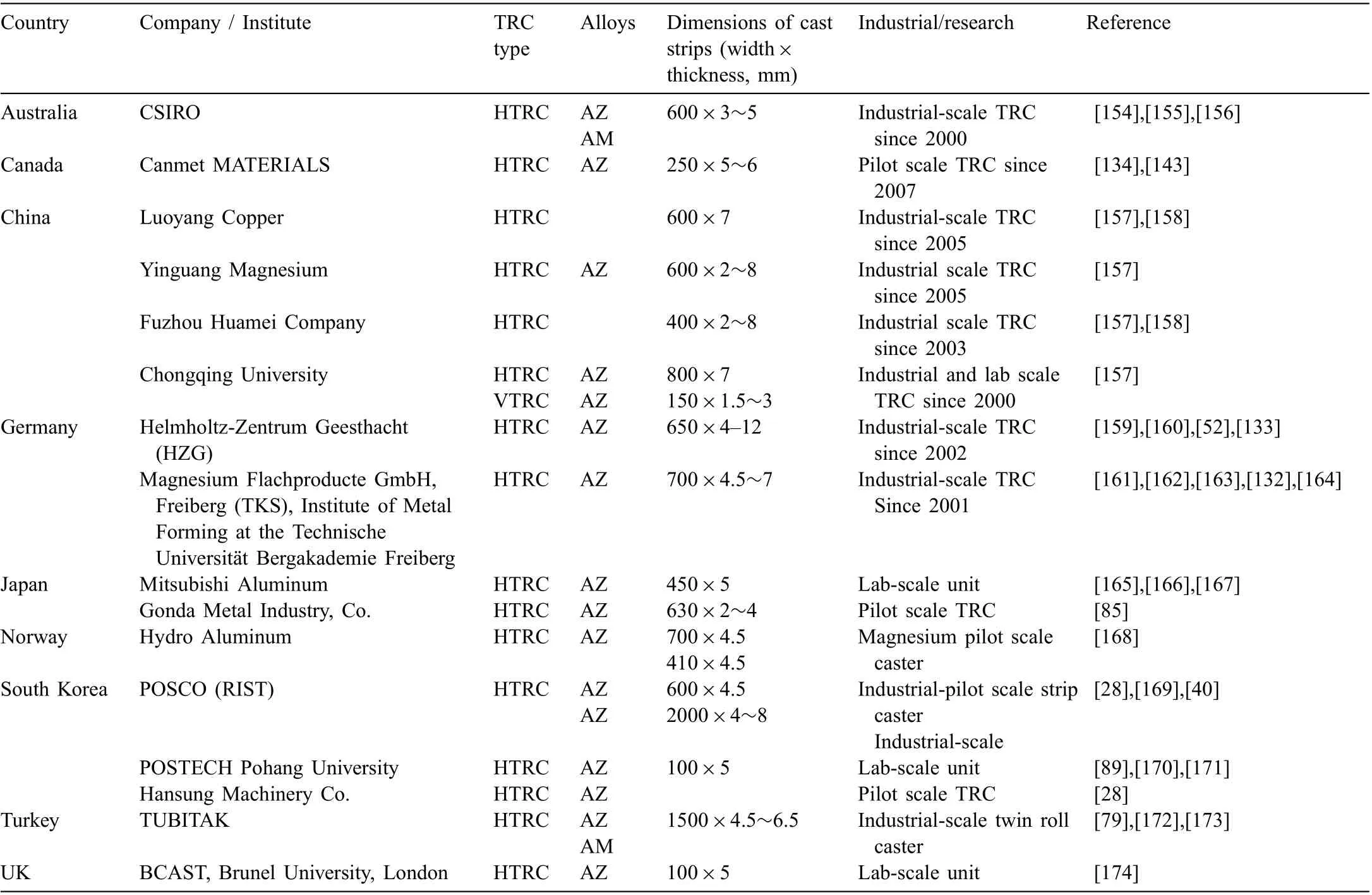
Table 3 Global R&D centers of magnesium TRC technologies.
In 2001 Thyssen Krupp Stahl (TKS) AG, Germany set up an organization Magnesium Flachprodukte GmbH (MgF)in Freiberg. The facility, which is used in cooperation with Institute of Metal Forming at the Technische Universität Bergakademie Freiberg, manufactures strips with 700mm width and 4 to 7mm in thickness [72]. It consists of a gasfire melting furnace with a melting capacity of approximately 750kg/h,an electrically heated feeding system,a twinroll-casting mill stand with water-cooled rolls, a pinch roll unit, a cross-cut shear and a coiler. The investigated alloys are ZE10, ME21 and WE43, AZ21 and AZ31 alloys [132].The twin roll caster at the Hemholtz-centre Geesthacht(HZG)has capabilities to manufacture magnesium strips with a maximum width of 650mm and a thickness of 4-12mm at a maximum rolling speed of 4m/min. It consists of the Novelis Jumbo 3CM TRC with rolls diameter of 600mm, equipped with the Striko Westofen furnace line, having a capacity of 100kg/min with ingot preheater [133].
An industrial scale magnesium twin roll casting plant has been set up in Turkey by the Materials Institute, TUBITAK MRC. The TRC system is equipped with a gas fire chamber furnace with a maximum melting capacity of 3200kg magnesium. Water-cooled steel twin-rolls of 1600mm width and 1125mm diameter with 15° tilt angle, a pinch roll unit, a cross-cut shear and a coiler are incorporated into the system. The TRC manufactures the 1500mm wide strips with a thickness of 4.5-6.5mm from AZ31, AZ61, AZ91, AM50 and AM60 alloys. As part of the same development, work has also been conducted on warm rolling of the TRC strip into thin sheet [79].
In South Korea, research on magnesium sheet technology was initiated in 2004 by Research Institute of Industrial Science and Technology (RIST) with support of Pohang Iron and Steel Company (POSCO) [40]. They integrated melting,twin roll casting and rolling operation capable of continuously producing 600mm wide strip in gauges from 3 to 7mm and coils up to 1220mm diameter. Development work covered also melting and casting technology, high speed warm rolling,stronger, more ductile alloys, welding and superplastic forming. As outcome, POSCO has started in 2007 the world’s firs commercial scale production of magnesium coil followed by a development of the wide strip casting technology with a strip width of 2000mm and 4~8mm thickness, using AZ31 and AZ61 alloys. The cast strip after further processing is used for automotive components [134]. At present, developments in Korea achieved the most advanced commercialization.
A review of global R&D activities shows that despite substantial progress the TRC technology of magnesium strip is at very early commercialization stages. There are still technological barriers, related both to the magnesium alloy nature and hardware performance. Since large portion of research is performed at a small scale in a laboratory environment, unknown remains the effect of scale-up from a laboratory unit to commercial production [131].
9. Research at CanmetMATERIALS
The pilot-scale twin roll caster at CanmetMATERIALS is unique and the only system in North America, devoted to magnesium. It serves as a development hub for new technologies. The early research on magnesium was funded primarily through two federal programs: the Canadian Lightweight Materials Research Initiative, and the Materials and Manufacturing Theme of the AUTO21 Network of Centres of Excellence. During 2009-2015, the research on magnesium alloys was supported by Natural Sciences and Engineering Research Council of Canada (NSERC) forming the Magnesium Network, MagNET, connecting CanmetMATERIALS,industry and Canadian universities.
The equipment was originally installed in 2007 at the previous laboratory location in Ottawa. In 2010 the machinery was moved to the present laboratory location in Hamilton,Ontario, where over next years a substantial upgrade took place. The TRC system is a part of the pilot scale facility containing foundry with melting furnaces, casting presses and rolling mills. The goal of magnesium project is to conduct research and develop technologies along with processing strategies for the production of low cost magnesium alloy sheet.The TRC expanded existing magnesium expertise,which covered mechanical and corrosion performance of high-pressure die castings, gravity and low pressure castings using permanent and sand molds, sheet rolling and magnesium matrix composites [135].
9.1. TRC mill stand and auxiliary equipment
The basic and auxiliary equipment of the twin roll caster is shown in Fig. 20. The system consists of twin-roll caster stand from Novelis in Kingston, Ontario, a magnesium melting furnace from Rauch in Austria, pinch roll and shear from US and caster upgrade and downstream equipment from Novelis PAE, France.

Fig. 20. Schematic diagram showing components of twin roll caster at CanmetMATERIALS.

Table 4 Basic geometry of the TRC pilot system at CanmetMATERIALS and its typical operating conditions.
The TRC mill stand is instrumented with optical sensors and thermocouples for monitoring and temperature control in the furnace, head-box, nozzle inlet/outlet, roll surface, cooling water and strip exit. The system is also equipped with sensors for roll separating force, liquid level in the head-box and rolling speed. Basic geometry of the caster and typical operating parameters are listed in Table 4. In present configuration the facility can produce 250mm wide magnesium strip using 355mm diameter water-cooled casting rolls that are 610mm wide.
Having a furnace with capacity of 400kg magnesium and automated melt delivery system the caster is sized to manufacture strip large enough for both the material property measurement at various angles to the rolling direction, as well as assessment of metal forming processes. The TRC mill has a fully integrated HMI (Human Machine Interface) that collects all the process information/data during strip casting [136].The experiments involved strips of AZ31 with two widths of 150 and 250mm and two thicknesses of 5 and 6mm(Fig.21).
9.2. Hardware performance
While magnesium exhibits high affinit to oxygen, at temperatures corresponding to semisolid or liquid states it is also highly corrosive towards materials it contacts [32]. This imposes challenges to the selection of materials used to contain,transfer or process molten magnesium during manufacturing operations. Understanding the reactivity of liquid magnesium with TRC hardware components to eliminate or at least reduce the progress of corrosion is paramount for smooth strip casting.

Fig. 21. Manufacturing of magnesium strip at twin roll casting facility of CanmetMATERIALS.
9.2.1. Feeding system of molten magnesium
There are still unsolved challenges with TRC hardware performance in harsh environment of liquid magnesium.Among many machine components, feeding system of molten magnesium alloy to the rolls creates challenges. In particular the performance of ceramic nozzle and rollers, distributing liquid metal at the start of the process adversely affect the strip quality. Inadequate melt supply, due to the fl w characteristics in the nozzle, was hypothesized to lead to lateral freezing of the strip edges. To improve the feeding nozzle design, computer modeling was used to minimize lateral freezing fronts in the edge of the strip by optimizing the nozzle size and geometry [136].

Fig. 22. Melt feeding system to rolls of the TRC: (a) and plots from nozzle thermocouples with locations shown in (a) and strip-velocity sensors (b).
The TRC is instrumented with process control sensors and the thermocouple readings provide input and validation data for the finit volume modeling (Fig. 22). To gain a better understanding of the impact of the nozzle design and operating parameters, a three-dimensional model of the TRC was constructed using the finite- olume-based STAR CCM+ software. The multi-phase computations were carried out using the implicit time integration. A marked feature of the computations is the inclusion of surface tension of melt, the interaction of melt with air, and rotating rolls with varying speed.According to major findings there is significan recirculation of the fl w in the nozzle, which could lead to insufficien melt supply to the gap between the rolls and contribute to the observed defects (Fig. 23).
9.2.2. Contact of molten and solid magnesium with the rolls
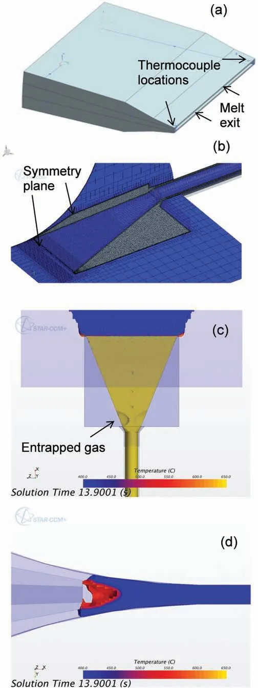
Fig. 23. Numerical modeling of delivery of molten metal to casting rolls: (a)ceramic nozzle, 250-mm wide; (b) polyhedral mesh in solid nozzle, hexahedral trim mesh to model the fluid (c) air pocket at nozzle-box interface; (d)temperature fiel from three-dimensional computation at 13.9 s. Reprinted from Ref. [136].
To transfer heat to the rolls and allow solidification there has to be a contact between liquid magnesium and the caster rolls. At the same time the alloy after solidificatio cannot stick to the rolls since it would lead to strip defects. The melt-roll contact is controlled by process parameters. When the caster is running too hot and too fast, solidificatio is not completed before the kissing point and the magnesium strip surface defects appear such as excessive surface oxidation (burnout), surface cracks due to solidificatio shrinkage or hot tearing and internal oxide inclusions. Therefore, an interaction of firs liquid and then solid magnesium with rolls is of primary importance for strip formation and its quality.While considering strip formation, four stages are generally distinguished:
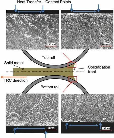
Fig. 24. Microstructural details of the contact between casting rolls and strip showing locations of high heat transfer.
1. Liquid magnesium alloy provided by the nozzle tip contacts the cold rolls, resulting in good heat transfer;
2. Solidificatio of magnesium on rolls takes place what results in shrinkage, reducing the contact surface and heat transfer;
3. As both solidificatio fronts, progressing from both rolls,meet, the contact between magnesium and rolls increases again due to high pressure imposed by the rolls what translates to better heat transfer;
4. After magnesium passes through the kissing point the contact with rolls decreases drastically and the same happens to heat transfer.
The microscopic observations of surface and near-surface regions of the strip reveal a scenario of its contact with the rolls. An example is shown in Fig. 24. Sticking of the sheet to the rolls, buckling, and deformation segregations constitute the common challenges of the TRC process that have to be addressed through appropriate tuning of the TRC parameters.
9.3. Process modeling
Hardware characteristics and process settings of the twin roll caster at CanmetMATERIALS are used as input and verificatio data for numerical simulations to provide a quantitative basis for optimizing the process variables to ensure high-quality sheet products.
The overall objective of McGill University computer modeling project was to formulate a simple linear multivariable model for the horizontal TRC system [137]. It aimed at understanding the fundamental dynamics involved in the process of interest and then developing a linear multivariable dynamic model that captures the fundamental dynamics of a horizontal twin roll caster.A secondary aim was adopting the linear multivariable dynamic model to design a controller that provides stable and an acceptable performance for set-point tracking using different methodologies such as classic control and Hinfinit control. In addition, an effort was made to fin the optimal parameters of the processing window including the casting speed, which is of paramount importance in defin ing the exit strip quality and thickness, using a mathematical model equation that is verifie through numerical simulation results.
As a result of modeling at University of Waterloo a finite element method (FEM) thermal-fluid-stres model has been developed and validated for twin roll casting of the AZ31 alloy [138],[139],[140],[141]. The validation was performed by comparing the predicted exit strip temperature and secondary dendrite arm spacing through the strip thickness with those measured and obtained by experiments. The model was then used to quantify how the thermo-mechanical history experienced by the strip during TRC would change as the equipment was scaled up from a laboratory 355mm rolls to a pilot scale with 600mm rolls and to an industrial scale machine with 1150mm rolls. The model predictions showed that the thermal history and solidificatio cooling rate, experienced by the strip, were not affected significantl by caster scaleup. However, the mechanical history experienced by the strip did change remarkably depending on the roll diameters. In particular, casting with bigger rolls led to the development of higher stress levels at the strip surface. The roll separating force per mm width of strip was also predicted to increase significantl when the TRC was scaled to larger sizes. Using the model predicted results, the effect of both casting speed and roll diameter was integrated into an empirical equation to predict the exit temperature and the roll separating force.Using this approach, a TRC process map was generated for AZ31, which included roll diameter and casting speed.
9.4. Strip microstructure
Detailed examination of strip microstructure and properties provides feedback for process parameters settings and alloy chemistry design.
9.4.1. SDAS vs solidification rate
The microstructural observations of magnesium strips,manufactured at different process settings, lead to conclusion that, in general, there is no symmetry between individual zones in regards to the strip centerline. The microstructure of the as-cast strip manufactured using TRC is very fin in nearstrip surface regions. Then, it contains columnar dendrites at the quarter thickness of the strip and equiaxed grains in the strip center. As seen in Fig. 25, there is no symmetry between two columnar zones: the upper zone contains coarser dendrites with quite different alignment than that seen in the bottom columnar zone.
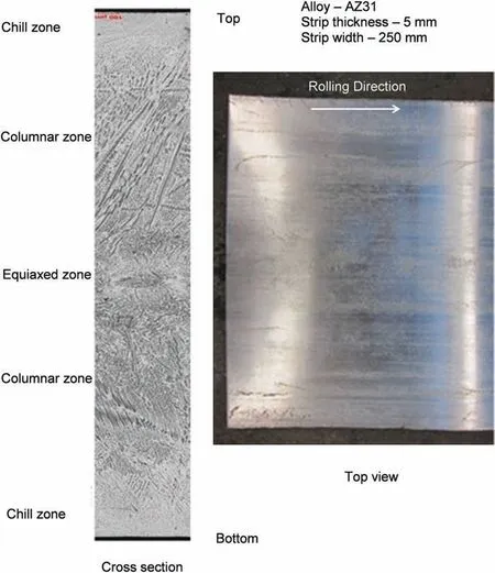
Fig. 25. Top surface view and cross section of the AZ31 strip with thickness of 5mm and width of 250mm with individual zones and asymmetric microstructure of top and bottom columnar zones.
The quantitative description of the strip microstructure is often expressed through secondary dendrite arm spacing(SDAS). As seen in Fig. 26, SDAS is directly affected by cooling rate. There are experimental formulas in the literature linking cooling rate (R) with secondary dendrite arm spacing (λ) and an example for the AZ31 and cooling rate from 10-1to 106°C/s, is expressed as follows [142]:

This empirical relation may be used to correlate the cooling rate and SDAS. Since the lowest cooling rate occurs in the strip center, there would be the largest SDAS with symmetric(in relation to the center line position) change to the smallest SDAS, predicted at both surfaces.
The experimental measurement of SDAS across the strip thickness is shown in Fig. 27. When the maximum SDAS is confirme in the strip center, measured values of SDAS in both columnar zones exhibit a lack of symmetry. Hence, assuming symmetry during consideration of solidificatio and heat transfer during TRC contradicts experimental observations.
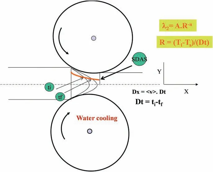
Fig. 26. Schematics showing secondary dendrite arm spacing, SDAS, (λ)versus solidificatio rate (R) correlation during TRC.
9.4.2. Segregations in mid-plane of the strip
There is also an important task with controlling the strip quality around the center line. The centerline of the strip is created through joining two solidificatio fronts developed by alloy solidifying on top and bottom rolls. As seen in Fig. 28,image contrast indicates inhomogeneity in phase composition within about 400μm thick layer of the strip. Since the center region is the last one to solidify,it is expected to see a residual shrinkage in the strip center. The spherical pore morphology with their dense distribution suggests gas porosity,likely from SF6used to shield magnesium entering the TRC rolls.
9.4.3. Post TRC processing

Fig. 27. Cross sectional analysis of the strip microstructure (top) and plot of measured secondary dendrite arm spacing across the TRC strip thickness (bottom).Alloy AZ31.
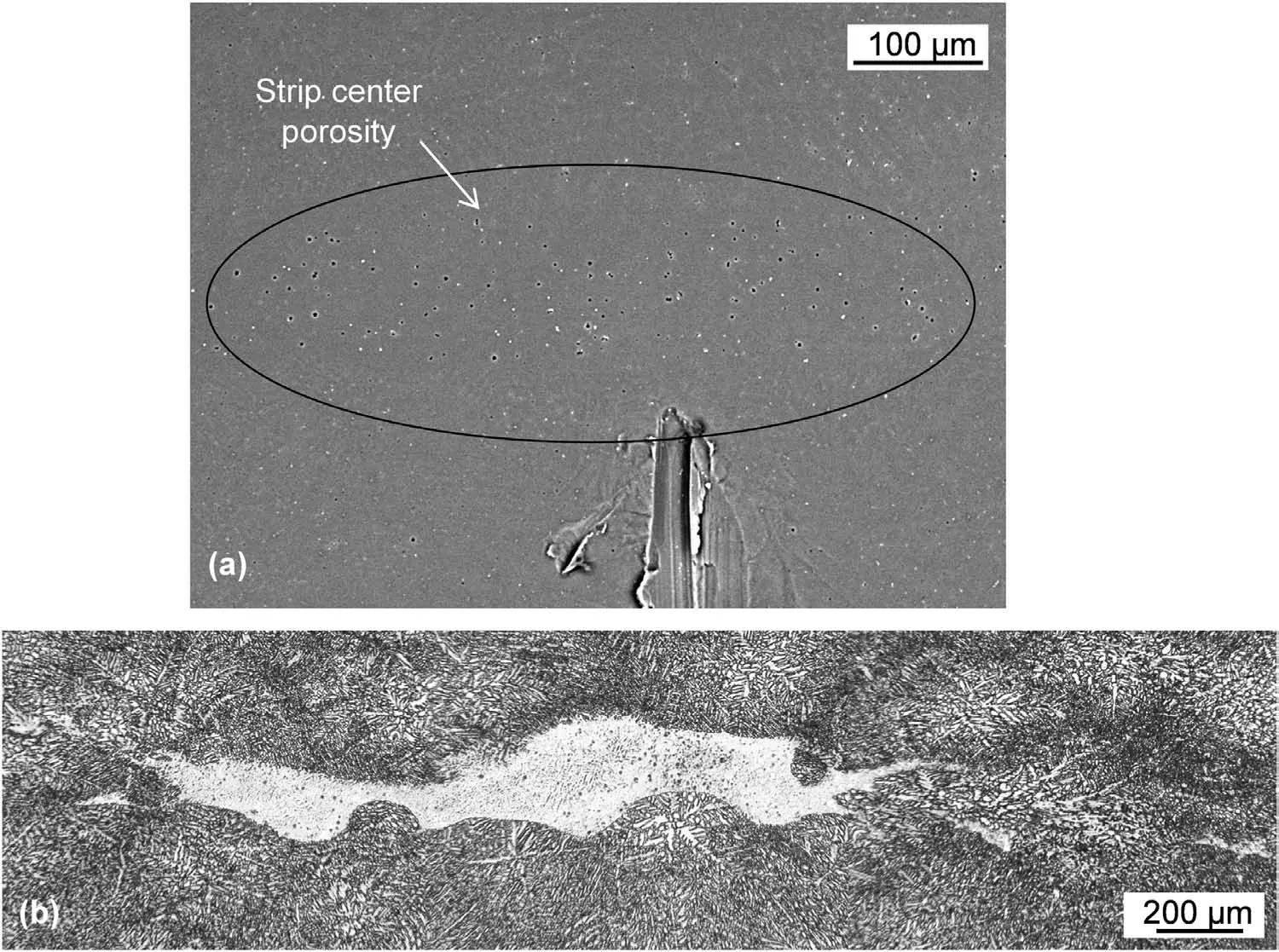
Fig. 28. Center line inhomogeneity within the AZ31 strip, 250mm wide, 5mm thick: (a) porosity concentration; (b) microstructure inhomogeneity with image contrast suggesting differences in phase composition.

Fig. 29. Effect of post-TRC treatment on microstructure of 5mm thick strip of AZ31 alloy: hot rolling at 450 °C from 5mm to 2mm and annealing of hot rolled sheet at 450 °C.
To manufacture a thin sheet from magnesium alloy, the TRC strip is subjected to further rolling and heat treatment.Thus,its formability during post-TRC processing is important.A transformation of strip microstructure during subsequent rolling and heat treatment is shown in Fig. 29. Hot rolling at 450 °C involves dynamic recrystallization refinin he grain size. Hot rolled microstructure is fine-graine with equiaxed grains being smaller in near surface region. There is seen some grain inhomogeneity in the quart and strip center where bands of larger, irregular shape grains are present. Additional annealing conducted at the same temperature as that one used for rolling, improves homogeneity of grain size, where bands with irregular grain disappear, positively affecting the sheet properties [143].
9.5. Oxidation effect on strip quality
A search for the solution to prevent magnesium oxidation during TRC is the essential direction of strip development. At high temperatures, especially that corresponding to semisolid or liquid states, molten magnesium alloys exposed to an oxidizing atmosphere react rapidly leading to catastrophic oxidation, ignition and combustion [1],[144]. To prevent oxidation and burning during TRC operations, magnesium alloys are protected by cover atmospheres [33]. The use of present protective atmospheres (SF6) increases manufacturing cost and heavily contributes to greenhouse gas emissions. Therefore,in addition to a search for new generation atmospheres there is an effort to reduce the reactivity of magnesium alloys by a modificatio of their chemical composition [145]. The improved oxidation resistance of alloys is of importance since the molten or hot solid metal cannot be protected by a gas during transfer from a furnace to rolls of a twin roll caster,during solidificatio between rolls and after leaving rolls as still hot solid strip [146].
A TRC practice shows that, despite using protective atmospheres, magnesium oxidation exerts effect on strip quality.As a result of reaction with oxygen, strip surface is covered with oxide (Fig. 30). If strip temperature is too high,extensive oxidation leading to local ignition may completely damage the strip (Fig. 31).
Magnesium reactivity affects also internal quality of the strip.After oxidation,experienced at different stages of liquidstate processing, the alloy contains a certain volume of oxides, predominantly magnesia MgO or also spinel MgAl2O4in grades containing Al. As opposed to solid state oxidation where oxide remains on the metal surface, oxide formed initially on a surface of the liquid alloy is subsequently entrained into the alloy volume [145]. The entrained oxide may reside inside a component as non-metallic inclusions or serve during solidificatio as nucleation sites of pores and other casting defects, thus reducing fina properties, especially the fatigue resistance. It is clear that controlling and minimizing oxidation of magnesium alloys during TRC is of strategic importance with multiply aspects including economic with product cost and application opportunities, environmental, alloy and component quality, and personnel safety [147].
9.6. Development of magnesium alloys for TRC

Fig. 30. Top view of TRC strip showing surface quality issues due to oxidation (AZ31 alloy).
A substantial portion of research effort is dedicated to development of new alloys, tailored specificall for twin roll casting. In search for alloying elements, rare earth elements attract a special attention since they weaken the basal texture and improve the room temperature formability [148],[149]. In addition the advantages of rare earth containing magnesium alloys are high strength, high creep resistance, acceptable corrosion behavior and improved flammabilit resistance.
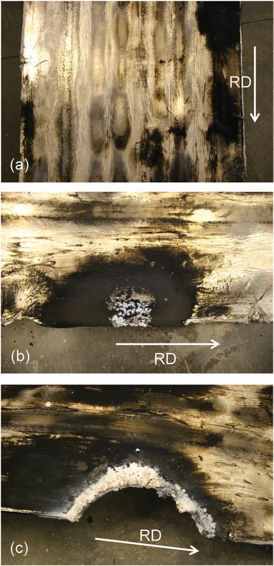
Fig. 31. Top view of TRC strip showing intensive oxidation after leaving rolls (AZ31 alloy).
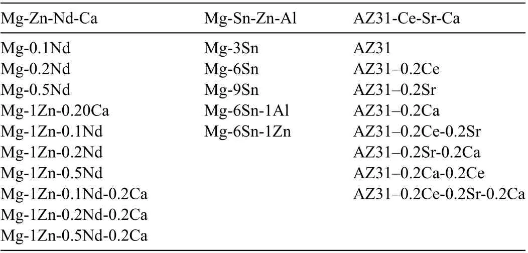
Table 5 Experimental alloys developed for sheet manufacturing through TRC technique. All values are in weight%.
Having modern foundry facility and expertise in alloy design, many experimental compositions were manufactured with testing their solidificatio characteristics and suitability for TRC. A list of experimental alloys melted at CanmetMATERIALS for investigation their properties towards application for sheet destination is summarized in Table 5. A combination of calculations using the FactSage software and measurements using a number of experimental techniques was explored to assess the solidificatio characteristics of experimental alloys along with commercial grades to determine the role of rare earth metals and calcium[150],[151],[152]. Casting parameters of various wrought magnesium alloys were evaluated with specificall designed wedge casting apparatus, equipped with water-cooled copper mold (Fig. 32). It was revealed that average SDAS of the as-cast strip produced by TRC is equivalent to that of the as-cast wedge at similar wedge thickness. Therefore,casting close to the wedge tip, can be used to simulate the microstructure of the twin roll cast strip. Thus, by verifying microstructure and properties of alloys solidifying at different rates, it was possible to select chemistry, which best suits the high solidificatio rates of TRC.
10. Present challenges
A review of the literature shows that within past decades,a substantial improvement in manufacturing of Mg strip at the global scale has been achieved. The progress is still required for Mg sheet to become a viable alternative to other materials. There is a continuous pressure from industry to reduce the operational cost of manufacturing processes. An advantage could be achieved through the TRC route of sheet manufacturing, which eliminates multiply operations. However, magnesium sheet must compete with both existing and new materials, such as steel, aluminum, titanium, plastics or composites based of both the cost and performance.
A challenge for TRC of magnesium is a protection of liquid Mg from oxidation by cover gas during transfer between metal delivery system components including furnace, tundish,nozzle and twin rolls. Development of a safe but simple protection for molten magnesium is crucial for achieving highquality sheet. Additional challenge is reactivity between nozzle material and liquid Mg alloys and a selection of material selection to avoid this reaction affecting cleanliness of Mg strip.
The problems with the conventional TRC process are coarse columnar grains of a size of approaching 1mm, severe chemical segregation at the center of the strip, large amounts of defects like bleeding and only casting dilute alloys with narrow freezing range. Molten magnesium freezes faster than molten aluminum wrought alloys. This tendency makes it more efficien to achieve uniform solidificatio across the sheet. Magnesium alloys have larger freezing ranges than aluminum wrought alloys what leads to formation of cracking and segregation defects in as-cast sheet.
It is anticipated that further progress in TRC of magnesium will be achieved through design of new alloys, tailored specificall for this manufacturing technique. The near-rapid solidificatio experienced by alloys during TRC requires alloys that take advantage of the increased amount of solute in the α-Mg solid solution, thus resulting in enhanced nucleation of precipitates within the matrix and their dense distribution. The features of microstructure modifications related to rapid solidification positively affect the strip formability at room temperature. Enhanced formability is an important enabler for the adoption of the sheet material for automotive body parts. There is also expectation that future alloys should exhibit improved oxidation resistance to prevent reaction during TRC processing. Recent studies have shown that magnesium when alloyed with rare earth elements may improve the above processing requirements and simultaneously performance characteristics required during service high strength, high creep resistance, acceptable corrosion behavior and improved flammabilit resistance.
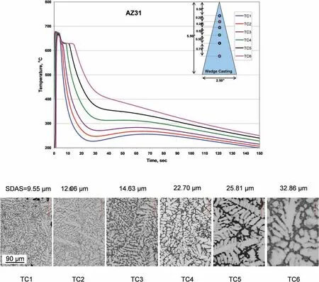
Fig. 32. Exploring wedge casting for alloy development for TRC: correlation between the cooling rate and microstructure of the AZ31 alloy. The secondary dendrite arm spacing measured for each cooling curve is indicated. Adapted from [175].
11. Summary
Twin roll casting is the effective manufacturing process of strips from ferrous and non-ferrous alloys and its expansion to magnesium is of paramount interest for modern industry. The technology is tested with magnesium alloys using the pilotand industrial scale equipment, installed in over 10 countries.At the small laboratory scale, there are attempts to explore TRC in non-conventional applications such as cladding,forming composite or amorphous strips or semisolid processing.So far, the predominant portion of R&D covers the wrought AZ31 alloy; however, there are trials with other commercial grades, having chemistry that is more complex. The need is emphasized for novel alloys, which would take advantage of unique conditions existing during TRC. The future alloys should also have an improved flammabilit resistance to prevent the strip-deteriorating oxidation during processing. Although a substantial progress has been achieved during recent decades,with the 2000mm wide strip being manufactured,the technology is still in its early commercialization stage. It appears that expansion of twin roll casting is hindered, in part,by nature of magnesium with its inherent low formability and high affinit to oxygen.
Acknowledgements
The authors thank Dr. Elchachmi Essadiqi and Dr. Mark Kozdras for overseeing the TRC activities, the CanmetMATERIALS team and external consultants for support during equipment modernizing and experimental trials.
Funding
The research was funded by the Program of Energy Research and Development (PERD) of Natural Resources Canada
杂志排行
Journal of Magnesium and Alloys的其它文章
- Mechanism of Mn on inhibiting Fe-caused magnesium corrosion
- An efficien and comparative adsorption of Congo red and Trypan blue dyes on MgO nanoparticles: Kinetics, thermodynamics and isotherm studies
- Twin recrystallization mechanisms in a high strain rate compressed Mg-Zn alloy
- Corrosion behaviour and cytocompatibility of selected binary magnesium-rare earth alloys
- Correlation between test temperature, applied load and wear transition of Mg97Zn1Y2 alloy
- Residual stress and precipitation of Mg-5Zn-3.5Sn-1Mn-0.5Ca-0.5Cu alloy with different quenching rates
