A hybrid tubular standing support for underground mines:Compressive behaviour
2021-04-08HongchoZhoTingRenAlexRemennikov
Hongcho Zho,Ting Ren,Alex Remennikov
a School of Civil,Mining and Environmental Engineering,Faculty of Engineering and Information Sciences,University of Wollongong,NSW 2522,Australia
b School of Geology and Mining Engineering,Xinjiang University,Urumqi 830000,China
Keywords:Standing support FRP PVC Confinement Composite structures Underground mines
ABSTRACT This paper presents the development of an innovative standing support for underground mines.The main feature of this standing support is its exterior container,a combination of polyvinyl chloride (PVC) with large rupture strain and fibre-reinforced polymer (FRP) with high strength-to-weight ratio.To demonstrate the advantages of this cementitious grout filled PVC-FRP tubular (PFT) standing support,a series of compression tests were conducted.Test variables included the strength of cementitious grout infill material and the thickness of FRP jacket.Compression tests were also conducted on cementitious grout-filled PVC tubular(PT) support and cementitious grout-filled FRP tubular (FT)support.These tests showed that PFT support presents a typical strain-hardening behaviour together with an outstanding axial deformation ability(>20%of the overall height of the support).In addition,the maximum compressive strength of PFT support is much higher than that of the corresponding PT support and FT support.Furthermore,using thicker FRP jacket or high strength cementitious grout material can enhance the load carrying capacity of PFT support.These comparative results indicated that the high performance of PFT support is mainly attributed to the combination of confining constituents (i.e.PVC and FRP) and infill material.
1.Introduction
With the continuous increase of mining depth,how to determine a suitable support system becomes to be critical for ground control engineers [1,2].The stability of problematic tailgates,bleeders,and large-scale intersections of longwall mining has drawn much attention [3,4].Poor serviceability of these problematic underground facilities will result in many problems including the disruption of ventilation and roof falls,and may have a major compact on the productivity and safety of the mining operations[5].To address these issues,various secondary standing supports including the timber chock [6],Propsetter system [7],and the CAN®support[8]have been utilized together with traditional bolt reinforcement system for underground mines [9].Among them,the pumpable standing support is believed to be one of the most popular products in the market [10].Casting in place with a fastsetting cementitious grout,the infill material of pumpable standing support is generally grouted into a fabric bag [10]or plastic tube [11]through the pump system.The foldable fabric bag or the telescopic plastic tube can provide full contact with roof without additional timber topped off,leading to the widely acceptances in more and more underground mines [10,12,13].
It has been well noted that the compressive behaviour of pumpable standing support is closely related to the infill material and exterior container.Because most popular cementitious materials(e.g.aerated cement,Portland cement,Portland pozzolan cement,ettringite-based cement) are generally the brittle materials [12],the limited deformation abilities restrict their wide utilizations.The effect of exterior container therefore becomes more important to maintain the integrity of the pumpable standing support with large deformation.
During the past decades,a large amount of engineering materials such as fabric[12]and polyethylene(PE)plastic[11]have been introduced to confine the cementitious grout material in different types of pumpable standing support systems.Compared with conventional pumpable standing support incorporating fabric bag(see Fig.1a),the alternative product,termed cementitious grout-filled plastic tubular support,shows its excellent performance in sustaining the integrity with large deformation (Fig.1b) [21].Most pumpable standing supports show a typical strain softening behaviour due to the relatively low tensile strength of the confining materials.To develop a strain hardening standing support,the fibre-reinforced polymer (FRP) composite,an emerging material in retrofitting/strengthening structures [14-16],was recently introduced into the fabrication of the cementitious grout filled FRP tubular (FT) support [17].The high strength-to-weight ratio of FRP composite makes it possible to obtain a strain hardening behaviour of concrete structures,as reported by the previous experimental studies [18-20].Different from concrete structures in civil engineering,the limited tensile strain of E-glass FRP used in FT support restricts the wide use in deep mining where the large axial deformation is the main concern.In addition,the brittle failure of FT support after the sudden rupture of FRP container(Fig.1c)is not expected from the design aspect.
Against this background,a conceptual pumpable standing support has been recently developed.Different from conventional pumpable standing support,the main feature of this novel standing support is that the exterior container is the combination of polyvinyl chloride (PVC) and FRP composite.For ease of reference,the cementitious grout-filled PVC-FRP tubular standing support is termed as PFT support in this paper.The combination of PVC and FRP in PFT support is expected to obtain the advantages of PVC tubular (PT) support and FT support.The large tensile rupture strain of PVC is expected to sustain the integrity of the pumpable standing support after the rupture of FRP composite.Meanwhile,the high strength FRP composite can contribute enough confining pressure on cementitious grout to achieve the potential strain hardening behaviour.Note that the simple change of the confining material will not affect the transportation and installation process of cementitious grout -filled plastic tubular support as shown in Fig.1b.
To demonstrate the expected advantages of this conceptual pumpable standing support,this paper presented a first ever experimental investigation on PFT columns subjected to axial compression.A total of 18 stub PFT specimens have been prepared and tested.The test variables studied in this research included the strength of cementitious grout material and the thickness of FRP composite.In parallel,the compressive behaviour of PT columns and FT columns were studied and compared.
2.Experimental program
2.1.Test specimens
A total of 34 specimens including 18 PFTs,6PTs,and 10 FTs were fabricated and tested in the High-bay Lab at the University of Wollongong.All specimens had a nominal diameter (i.e.inner diameter) of 152 mm and a height of 305 mm.According to the type of confining material (i.e.PVC+FRP,PVC,FRP),the waterto-powder ratio of cementitious grout material,and FRP thickness,these specimens were divided into three series covering nine groups.Three groups of PFT specimens with different water-topowder ratios of cementitious grout material were prepared in the first series.The specimens in group PFT-1.0 had two different thickness of FRP jackets(2-ply and 5-ply).Whereas three different thickness of FRP jackets (1-ply,2-ply,and 3-ply) were adopted for PFT specimens in other two groups with the water-to-powder ratio of 1.5 and 2.0,respectively.In the second series,6 PT specimens were divided into three groups according to the water-to-powder ratio of cementitious grout material.In addition,10 FT specimens were divided into three groups,covering different FRP thickness and water-to-powder ratio of cementitious grout material.Two or three identical specimens were prepared for each group.More detailed information about these specimens can be found from Table 1.
Each specimen is given a name,starting with its series name(i.e.PFT,PT,and FT),followed by a number to identify the waterto-powder ratio of cementitious grout material.The followed number is used to represent the number of plies of FRP jacket(i.e.1,2,3,or 5) if it exists.The last Roman number is used to differentiate identical specimens in each group.Taking PFT-1.5-3-I specimen for example,it refers to the first specimen in series PFT covered a 3-ply FRP jacket.The water-to-powder ratio of the cementitious grout material for this specimen is 1.5.
2.2.Material properties
2.2.1.Cementitious grout material
The high yield cementitious grout material was provided by China Mining &Civil New Material Science and Technology Co.,Ltd.The two-component powder material mixed with designed water was adopted to generate the cementitious grout material in the form of slurry.The main components of this cementitious grout material are the calcium sulphoaluminate cement,quicklime,gypsum,and some reactors [22,23].To investigate the compressive behaviour of cementitious grout material with different water-to-powder ratios at different curing ages,36 cylindrical specimens have been prepared and tested.All specimens had a dimeter of 152 mm and a height of 305 mm.The compressive strength of cementitious grout material,averaged from three identical specimens,are listed in Table 2.It is apparent that the compressive strength of cementitious grout material is closely related to the water-to-powder ratio.The smaller water-to-powder ratio can generally result in the high compressive strength of cementitious grout material at the same curing time.
2.2.2.PVC
PVC tube used in this experiment was provided by the local company.For each specimen with PVC tube,a white stormwater pipe with an inner diameter of 152 mm and a thickness of 3.5 mm was cut to the standard length(i.e.305 mm).Tensile properties of PVC tube were obtained from the tensile coupon tests on five dog-bone coupons,in accordance with ASTM D638-14 [24].The test set up of tensile test using the Nano digital strain camera is presented in Fig.2.

Table 2 Compressive strength of cementitious grout material at different curing time.
It is obvious from Fig.3a that the typical PVC coupon exhibited significantly ductile behaviour reaching to a large fracture strain of 65%.Similar to existing research on PVC coupon test [25],the tensile behaviour of PVC coupon can be divided into three portions:(1) the elastic linear part,(2) plastic bilinear part,and (3) the constant flat part.The unique tensile behaviour of PVC coupons,in particular,in the third part indicates that the tensile strength does not generally increase with the tensile strain.More detailed information about the PVC coupon tests can be found from Table 3.
Compressive behaviour of the hollow PVC tube was obtained by testing two hollow PVC tubes(i.e.PVC-I,II)in accordance with GB/T 5352-2005[26].These hollow PVC tubes were all failed with the global buckling(Fig.3b).Once the buckling observed from the hollow PVC tube,the load carrying capacity of PVC tube will significantly decrease,which can be found from the axial stress-axial strain curves shown in Fig.3b.Note that the axial strains presented herein were the nominal axial strains,which were calculated based on the axial deformation covering the overall height of the specimens.
2.2.3.UHMWPE FRP
Ultra-high-molecular-weight polyethylene(UHMWPE)is a subset of the thermoplastic polyethylene (PE),also known as highmodulus polyethylene (HMPE) or high-performance polyethylene(HPPE) [27].In the present experiment,UHMWPE fibre sheet(No.ZTZ 24) provided by Hunan Zhongtai Special Equipment Co.,Ltd,China was embedded into the epoxy resin to fabricate FRP composite.The styrofoam with the outer dimeter of 152 mm and the length of 610 mm was used as the mould for the preparation of FRP tube.To prevent the occurrence of premature debonding under compression,the additional fabric with a length of 152 mm was left as overlapping zone.
12 flat coupons with a nominal thickness of 0.135 mm per ply were cut from the UHMWPE FRP following ASTM D3039/D3039M [28].The typical tensile stress-strain behaviour of the UHMWPE FRP coupon can be seen from Fig.4.The UHMWPE coupons used in this experiment have an average tensile strength of 1980.84 MPa and an average Young’s modulus of 42.68 GPa.More detailed information about the properties of UHMWPE FRP and epoxy resin can be found from Table 4.Note that the average ultimate lateral strain of FRP (4.64%) is larger than that of the epoxy resin(3.40%),which may result in the debonding between FRP and epoxy resin during the test.

Fig.2.Tensile test set-up with Nano digital strain camera.
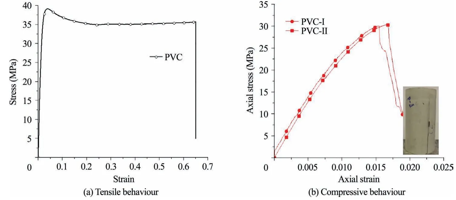
Fig.3.Behaviour of PVC under tensile and compression loading.

Table 3 Properties of PVC.
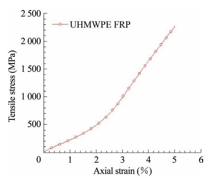
Fig.4.Typical tensile behaviour of FRP flat coupon.
2.2.4.PVC-FRP
Fig.5a shows the typical failure mode of the hybrid PVC-FRP tube,in which the 1-ply FRP jacket was wrapped on the surface of the PVC tube.Different from the plain PVC tube shown in Fig.3b,the buckling normally occurred near the ends of hollow PVC tube has been successfully changed with the additional confinement provided by the FRP jacket.In addition,the outward buckling deformation of hollow PVC tube has tended to inward.
Fig.5b shows the axial load-axial shortening curves of PVC-FRP tubes with different thickness of FRP jackets,in which two identical hollow PVC tubes were also presented for comparison.Once the inward buckling of PVC-FRP tubes happened,the axial load-axial shortening curves of these PVC-FRP tubes features an immediately descending.The other observation obtained from Fig.5b is that both the load carrying capacity and deformation ability of these PVC-FRP tubes with thicker FRP jacket are higher than that of their counterparts.
2.3.Preparation of specimens
The preparation procedure of PFT specimens included the following steps:(1) setting up of hollow PVC tubes on the waterproof wooden base(Fig.6a).The bottom ends of all PVC tubes were adhered to the base by sylinka;(2) mixing the two-component cementitious grout material with designed water in the plastic bucket (Fig.6b);(3) casting the well mixed cementitious grout material into the hollow tube and then covering these prepared specimens with the cling wrap to prevent the loss of moisture;(4) wrapping the FRP jacket on the surface of PVC tube (Fig.6c).In step 4,a continuous UHMWPE fabric embedded into the epoxy resin was wrapped on the PVC tube with the 152-mm-length overlapping zone.Note that the surface of the PVC tube was cleaned before the starting of wrapping process;and (5) both ends of the specimens were capped with the high strength gypsum plaster before the test (Fig.6d).
2.4.Test set-up and instrumentation
The 5000-kN compression testing machine(Fig.7a)was used in this research.Two liner variable displacement transducers(LVDTs)placed at the opposite corners between the bottom loading plate and the top steel plate were used to measure the overall axial shortening of specimen under compression.There are five strain gauges (20 mm length) installed at the mid-height of the specimens outside the overlapping zone for PFT specimens and FT spec-imens.Among them,two strain gauges were at 180° apart from each other to measure the axial strain while the other three strain gauges were used to measure the hoop strain (see Fig.7b).For PT specimens,only two hoop strain gauges and two axial strain gauges were uniformly attached on the mid-height region of the PVC tube.

Table 4 Properties of UHMWPE FRP and epoxy resin.
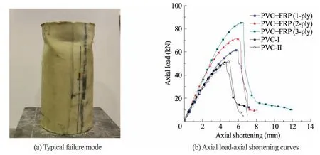
Fig.5.Compressive behaviour of hybrid PVC-FRP tube.

Fig.6.Preparation of specimens.

Fig.7.Test set-up and layout of strain gauges.
Displacement control was used to drive the compression machine at a constant speed of 0.8 mm/min for all compression tests according to ASTM D7012-10 [29].The relative low loading rate is adopted to obtain a progressive failure mode of specimens with large axial deformation.All test data,including the strains,load,and displacements,were recorded simultaneously by a data logger.
3.Experimental results and discussions
3.1.Failure modes
Fig.8a shows the typical failure modes of PT specimens with different water-to-powder ratios of cementitious grout material.It is apparent that all PT specimens experienced a serious buckling of the exterior PVC tubes.The non-uniformly outward buckling was distributed either near the end or at the mid-height region.This unique failure was different from the hollow PVC tube under compression,because the infilled cementitious grout material in PT specimen has restricted the potential inward buckling of the PVC tube.Note that these compression tests on PT specimens were prematurely terminated to protect the compression machine with limited displacement.It is believed that the large deformation ability of PT specimen could be achieved since there was no apparent rupture observed from the exterior PVC tube.
Different from PT specimens after tests,the obvious debonding of FRP tubes were observed for these FT specimens at large axial shortening (Fig.8b).The occurrence of these unexpected debonding before its rupture in tension indicated that the connection between UHMWPE fabric and epoxy resin was not strong enough.One of the main reasons for the occurrence of debonding is the tight surface of the UHMWPE fabric,resulting in the difficulty in embedding into epoxy resin.In addition,the relatively smaller tensile strain of epoxy resin should also be accounted for.Because these unexpected debonding would significantly affect the confining action of FRP on cementitious grout material,the axial load carrying capacity of FT specimen at the ultimate state was generally underestimated as well.
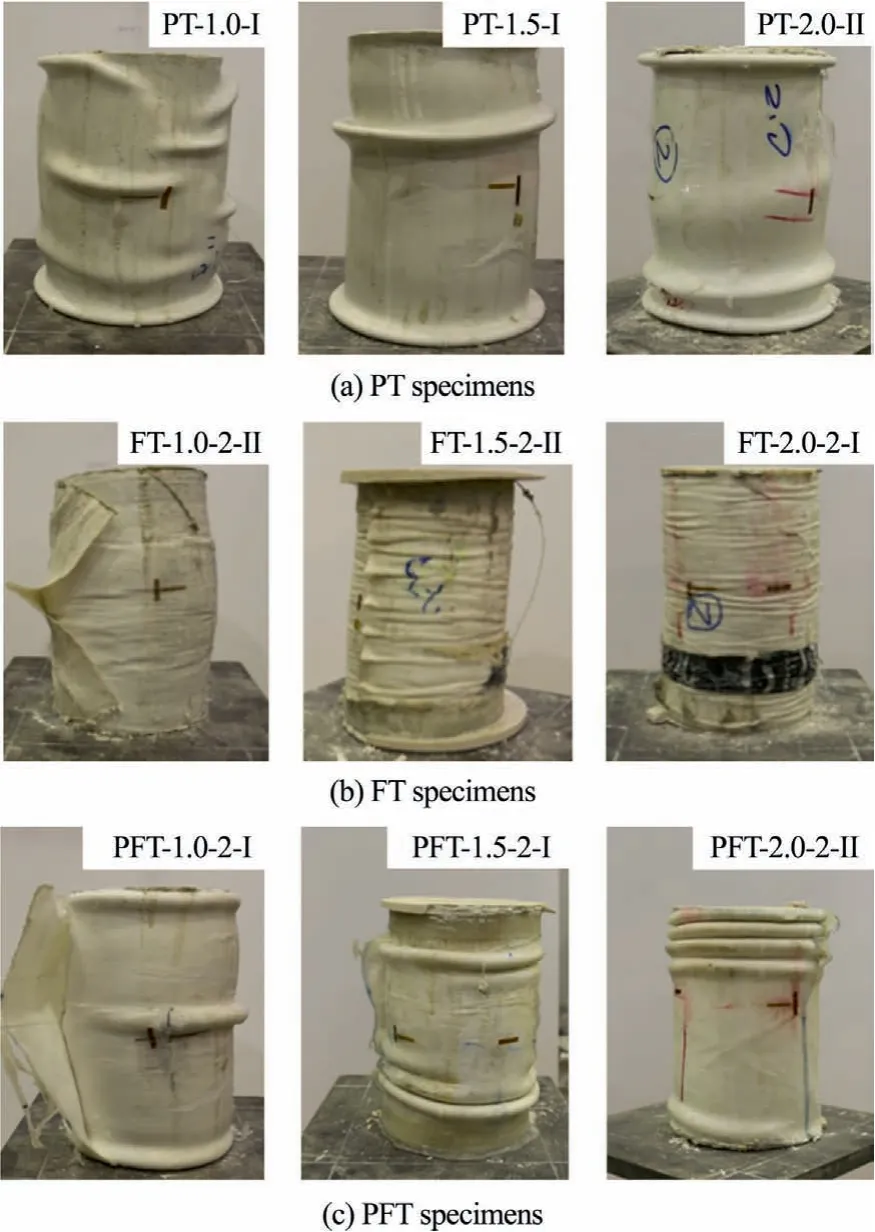
Fig.8.Typical failure modes of specimens after test.
Fig.8c depicts the typical failure modes of PFT specimens with different water-to-powder ratios of cementitious grout material.The rupture of FRP composite in tension was only observed from the mid-height of PFT specimen with small water-to-powder ratio(i.e.1.0) of cementitious grout material.The rupture of FRP jacket was around the mid-height of the specimen,nearby the buckling of PVC tube.In this case,the PVC tube with large tensile strain was expected to maintain the integrity of the tubular column after the rupture strain of FRP jacket was reached.With the increase of the water-to-powder ratio of cementitious grout material,only severe buckling was observed from the PVC tube in these PFT specimens rather than the rupture of FRP composite.Although the compression tests on PFT specimens were prematurely terminated,the failure of FRP jacket is expected to be earlier than PVC tube,due to its relatively small rupture strain.
3.2.Axial load-axial shortening behaviour
3.2.1.General behaviour of PFT specimens
Fig.9 shows axial load-axial shortening curves of all PFT specimens,the axial shortening of which was averaged from the reading of two LVDTs covering the overall height of the specimen.Most PFT specimens,excluding these from groups PFT-1.0-2 and PFT-1.5-1,were prematurely terminated when the large axial shortening(around 90 mm) of the specimens was reached.For specimens from groups PFT-1.0-2 and PFT-1.5-1,the compression tests were manually stopped when the serious debonding of FRP occurred.It is apparent that all specimens present a strain hardening behaviour associated with the large axial deformation before the termination of the compression tests.For ease of comparison,the given point corresponding to the axial shortening of 61 mm,equivalent to 20% of the overall height of the specimen,was determined as the ultimate state in this research,if there is no other specified.
To further investigate the behaviour of PFT specimens,Fig.10 shows the typical axial load-axial shortening curves of specimens from group PFT-1.0-2 together with the curves of the hybrid PVC-FRP tube and the cementitious grout material (abbreviated as CM in Fig.10).In addition,the sum of the cementitious grout material and hybrid PVC-FRP tube are listed in Table 5 for comparison.The axial load-shortening behaviour of cementitious material was directly averaged from three identical specimens tested at the same date with PFT specimens.In detail,for a given axial shortening of the cementitious grout material,the corresponding axial loads resisted by each identical specimen were collected and averaged.The axial load-axial shortening curve of the PVC-FRP tube was directly obtained from the preliminary test during the investigation of the material properties.The sum of cementitious material and the PVC-FRP tube was obtained by the similar method as mentioned above.It should be noted that only the axial load at the same axial shortening can be used for calculation to make sure the reliability for further comparison.
It is also apparent in Fig.10 that the ascending bilinear shape axial load-axial shortening curves of PFT specimens were not only much longer but also higher than that of the sum of cementitious grout material and the PVC-FRP tube,suggesting that the combination of three materials(i.e.PVC,FRP and cementitious grout material) achieved the superior compressive response compared to their performance alone.
The main mechanical properties of PFT specimens are listed in Table 5 for further comparison.In Table 5,the compressive strength of cementitious grout material and the PVC-FRP tube are denoted as Pcemand Ptube,respectively.The axial load resisted by the PFT specimen at the ultimate state corresponding to the axial shortening of 61 mm is termed as Ptotal.Note that PFT-1.5-1-I was terminated when the axial shortening was 58 mm and therefore the value of Ptotalfor which is not discussed in Table 5.The value of (Ptotal-Ptube)/Pcemis used to represent the contribution of the confinement provided by the hybrid FRP-PVC tube on cementitious grout material in PFT specimens.
3.2.2.Comparison between PFT specimens and PT specimens
The axial load-axial shortening curves of PFT specimens with a 2-ply FRP jacket are plotted together with the corresponding PT specimens with the same water-to-powder ratios of cementitious grout in Fig.11.Because the only difference between these PFT specimens and PT specimens in Fig.11 was the type of exterior container,the strain hardening behaviour of these PFT specimens were believed to be the contribution of the FRP jacket attached on the surface of PVC tube.Although the axial load-axial shortening curves of these PFT specimens are generally higher than corresponding PT specimens,the initial stiffness of PFT specimen and PT specimen was much similar,indicating that the effect of FRP jacket at the initial stage is not obvious.Further discussion on the effect of FRP jacket will be discussed in the following section.
The inward buckling mode of PVC tube can be restricted when it was filled with cementitious grout material,however,the outward buckling of PVC tube in PT specimen still resulted in the occurrence of load shedding events as shown in Fig.11.Even though,the PVC tube with large rupture strain sustained the integrity of PT specimen after the occurrence of outward buckling.Different from PT specimen,the additional FRP jacket attached on the surface of PVC tube in PFT specimen can only postpone the occurrence of PVC buckling and provide additional confinement to infilled cementitious grout material.The FRP jacket cannot totally prevent the occurrence of PVC buckling when large axial deformation was reached (see Fig.5a).As a result,some load shedding events still occurred for PFT specimens.

Fig.9.Axial load-axial shortening behaviour of PFT specimens.
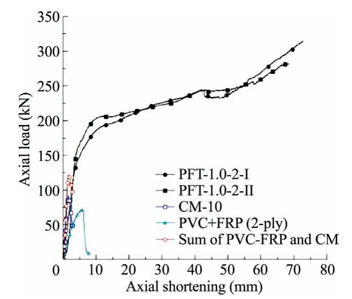
Fig.10.Typical axial load-axial shortening curves of PFT specimens.
3.2.3.Comparison between PFT specimens and FT specimens
Fig.12 compares the axial load-axial shortening curves of PFT specimens and corresponding FT specimens with the same water-to-powder ratio of cementitious grout material.It is apparent that the peak load of PFT specimen before the transition point is larger than that of FT specimen.The direct reason is that the load carrying capacity of the PVC-FRP tube is larger than that of FRP tube alone attributed to the load carrying capacity of the PVC tube.With the increase of the axial shortening,the axial load-axial shortening curves of PFT specimens are in parallel with the curves of FT specimens,except for specimen from group PFT-1.0-2 associated with unexpected debonding of FRP jacket.This unique observation indicated that the strain hardening behaviour of PFT specimen was mainly attributed to the exterior FRP jacket in the hybrid PVC-FRP tube.It can be also found that there were some fluctuations observed from the axial load-axial shortening curves of PFT specimens rather than FT specimens.These load shedding events were attributed to the buckling of PVC tube,which has been previously discussed.
3.3.Confining action of PVC-FRP tube on cementitious grout material
The cementitious grout material in PFT specimen is confined by the PVC tube and the FRP jacket together.The combined confining action of hybrid PVC-FRP tube is graphically illustrated based on the force equilibrium for each material shown in Fig.13.
As depicted in Fig.13,the confining pressure provided by the FRP jacket (flF) and the PVC tube (flP) can be expressed by Eqs.(1)and (2),respectively.

where Efand Epare the elastic modulus of FRP and PVC,respectively;tfand tpthe thickness of FRP jacket and PVC tube,respectively;d the diameter of the cementitious grout material,which is equal to the inner dimeter of the PVC tube;and εhthe lateral strain of cementitious grout material under compression.Assuming that no slippy occurred between FRP jacket and PVC tube,the same lateral strain(εh)is therefore adopted for the calculation of the confining pressure provided by the FRP jacket and the PVC tube.
The total confining pressure applied on the cementitious grout material (fl’) in PFT specimen can be obtained through Eq.(3).

Based on the above theoretical analysis,the typical axial loadaxial shortening curves of unconfined cementitious grout material,PT specimen,FT specimen,and PFT specimens are plotted together in Fig.14a.In addition,the hoop strain-axial shortening curves of these specimens are presented in Fig.14b,in which the hoop strains were averaged from two or three hoop strain gauges attached in the mid-height of the specimens.

Table 5 Key results of PFTs.

Fig.11.Comparison of the axial load-axial shortening behaviour between PFT specimens and PT specimens.
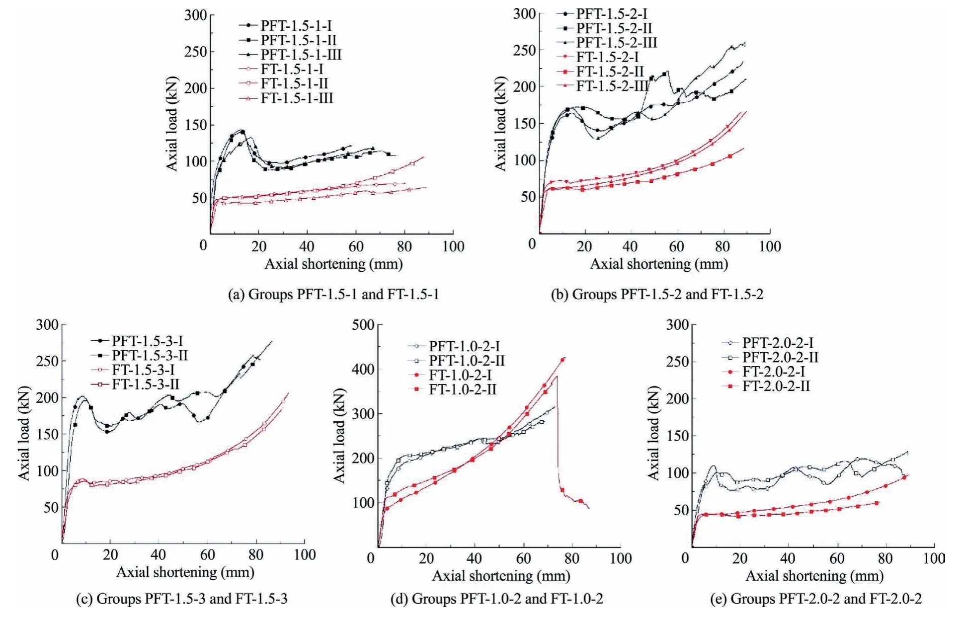
Fig.12.Comparison of axial load-axial shortening behaviour between PFT specimens and FT specimens.

Fig.13.Confining action of hybrid PVC-FRP tube on cementitious grout material.
At the initial testing stage,the lateral expansion of the PVC tube in PT specimen is much obvious than that of cementitious grout material due to the large Poisson’s ratio of the PVC (see Fig.14b).As a result,the confining action of PVC tube will only work until the radial compression stress appears between the interface of the PVC tube and infilled cementitious grout material.Different from PVC tube,the FRP jacket with linear elastic tensile behaviour can provide effective confining pressure on cementitious grout material in FT specimen from the initial loading stage.Therefore,the elastic modulus of confined cementitious grout material in FT specimen should be larger than that of PT,which agrees well with the observations shown in Fig.14a.When the hybrid PVC-FRP tube is used in PFT specimens,the large confining pressure applied on the cementitious grout material results in the relatively large elastic modulus of PFT specimens.
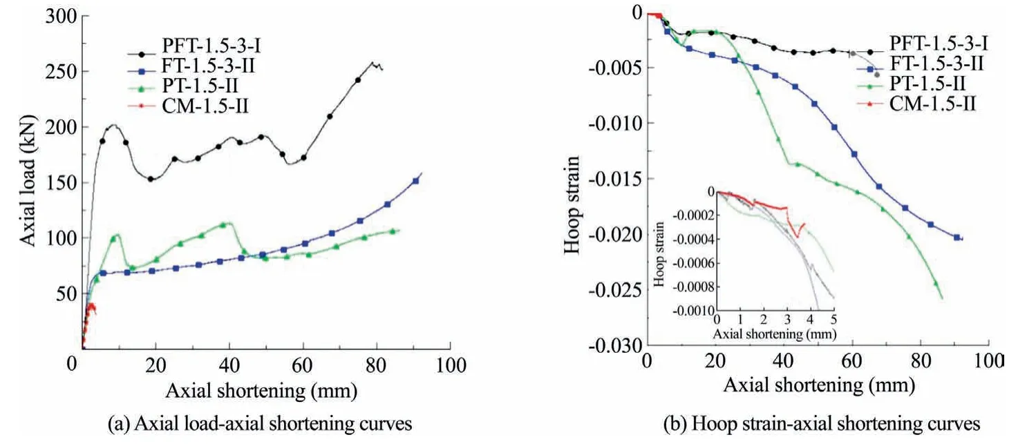
Fig.14.Comparison between unconfined and confined cementitious grout material in different specimens.
Theoretically,the axial load-axial shortening behaviour of PFT specimen is designable through changing the confining pressure applied on cementitious grout material.As illustrated in Eq.(3),the following methods can be adopted:(1)increasing the thickness of FRP jacket or PVC tube.Due to its high strength-to-weight ratio,increasing the thickness of FRP jacket is highly recommended.The effectiveness of using thicker FRP jacket to obtain the higher axial load-axial shortening curves of PFT specimens has been demonstrated in Fig.9b;(2)selecting FRP or PVC with larger elastic modulus,which has not yet considered in this paper.
Apart from the confining material itself,the lateral dilation behaviour of cementitious grout material will also affect the behaviour of PFT specimen under compression.When other parameters are the same,the large lateral strain of cementitious grout material will result in a higher confining pressure.However,some water was extruded from the confined cementitious grout material with large water-to-power ratios (e.g.1.5 and 2.0).Due to the loss of water,the failure modes of confined cementitious grout were much different from that without confinement (see Fig.15),the latter of which seems to be somewhat brittle.
As expected,the lateral dilation of cementitious grout material should experience a continuous increase with applied the axial loading.However,the loss of water indicated that the lateral dilation of cementitious grout material experienced the reduction.It is apparent in Fig.15 that the lateral deformation of PFT specimen is smaller than that of PT specimen and FT specimen,which can also be found from Fig.14b.The water loss significantly affects the slope of the second portion of the axial shortening curves of PFT specimens.For these PFT specimens with large water-to-powder ratio of cementitious grout material,much more water will be easily to extrude at a given confining pressure.As depicted in Fig.16,the axial loads of specimens from group PFT-1.0-2 increased quickly than their counterparts with larger water-topowder ratios of cementitious grout material.
Note that all above discussions are based on the small-scale tests.For PFT specimens with large dimension,the effective confining pressure applied on infilled cementitious grout material will be changed,which can be theoretically calculated by Eq.(3).When the same mechanical behaviour of PFT specimen shown in this experimental test is expected,the thicker FRP jacket should be applied to provide the same confining pressure.
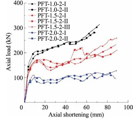
Fig.16.Effect of the water-to-powder ratios of cementitious grout material on behaviour of PFT specimens.
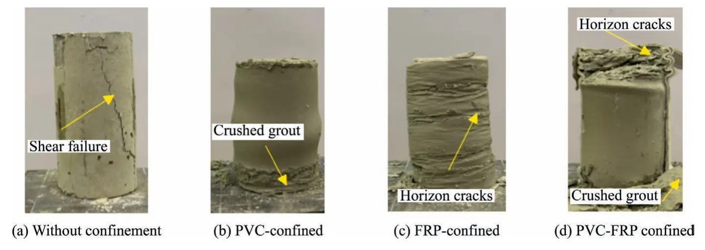
Fig.15.Failure mode of cementitious grout material confined by different materials.
4.Conclusions
A novel hybrid structure,namely cementitious grout materialfilled PVC-FRP tubular (PFT) standing support,has been recently developed for underground mines where the integrity of the structure is critically important.Compared with conventional pumpable standing support,the main feature of this new standing support is its container made of the hybrid PVC-FRP tube.The combined use of PVC with large tensile strain and FRP with high strength-to-weight ratio results in the superior compressive behaviour of PFT support.To verify the expected structural response of the hybrid standing support,a series of compression tests were conducted.Test variable covered the strength of cementitious grout material and the thickness of FRP jacket.Based on the experimental results and discussions,the following conclusions can be drawn:
(1) Compared with cementitious grout material filled PVC tubular (PT) standing support,the axial load-axial shortening curves of PFTs feature an ascending strain-hardening behaviour associated with large axial deformation,demonstrating that the confinement provided by the FRP jacket attached on PVC tube is effective.
(2) Compared with cementitious grout filled FRP tubular (FT)standing support,the additional PVC tube increases the load carrying capacity of PFT,not only because the axial load resisted by the PVC tube but also attributed to the increased confining pressure provided by the PVC tube on the infilled cementitious grout material.
(3) From the design aspects,the load carrying capacity of PFT support can be enhanced by using thicker FRP jacket to provide large confining pressure on cementitious grout material.In addition,approximate water-to-powder ratio of cementitious grout material in PFT support will affect the behaviour of PFT support when the loss of water is considered.
It should be noted that the main objectives of this paper are to investigate the structural behaviour of the PFT standing supports with different configurations of infills and confinements,and to verify their performance and unique advantage.Before the field trials of the standing supports,further full-scale tests of PFT standing supports under different loading conditions (e.g.uniaxial and biaxial) should be conducted to optimise the geometric parameters of the standing support.Furthermore,the PVC and FRP have to be a fire resistant or flame retardant for underground use.
Acknowledgements
This work is supported by the Australia government through the Australian Research Council’s Industrial Transformation Research Hub for nanoscience based construction material manufacturing (IH150100006) and the Australia Coal Industry’s Research Program (C28068).The first author also wishes to thank the University of Wollongong for the financial support for his PhD study.Professor Tao Yu’s kindly support during the preparation of this paper is acknowledged as well.
杂志排行
矿业科学技术学报的其它文章
- Development of ensemble learning models to evaluate the strength of coal-grout materials
- An updated empirical model for ground control in U.S.multiseam coal mines
- Study on seepage and deformation characteristics of coal microstructure by 3D reconstruction of CT images at high temperatures
- Drilling signals analysis for tricone bit condition monitoring
- The influence of borehole arrangement of soundless cracking demolition agents (SCDAs) on weakening the hard rock
- Numerical assessment of the influence of former mining activities and plasticity of rock mass on deformations of terrain surface
