An experimental investigation of the fracturing behaviour of rock-like materials containing two V-shaped parallelogram flaws
2020-12-20JinjinTianDongjingXuTianhaoLiu
Jinjin Tian,Dongjing Xu,Tianhao Liu
College of Earth Sciences & Engineering,Shandong University of Science and Technology,Qingdao 266590,China
ABSTRACT The distribution characteristics and evolution law of rock mass fissures induced by mining are a key scientific issue in the study of deep rock mechanics.In this study,a series of uniaxial compression experiments was conducted on rock-like specimens containing double V-shaped prefabricated fissures at dip angles of α=β=45°,α=45°<β=60°,α=β=60°,and α=60°<β=75° with a rock mechanics servocontrolled testing system.According to the experimental results,the effects of the dip angles of the double V-shaped prefabricated flaws with the same area on the mechanical parameters and fracturing process of the specimens were analysed in detail.Additionally,the crack initiation stress presented a nearly linear growth trend,which is generally similar to that of the crack peak stress with increasing flaw dip angle.By applying photographic monitoring to the crack initiation,propagation,coalescence,and failure modes in rock-like specimens,it was easily seen that the V-shaped flaw properties slightly influence the crack initiation positions but significantly influence the crack trajectories.The crack failure modes can be summarized into two distinct types.The study reported herein can provide a better understanding of the evolution of double V-shaped prefabricated fissures induced by coal mining.
Keywords:V-shaped fissure Fracturing process Overburden strata Coal mining
1.Introduction
Longwall mining has historically been used for underground coal extraction.As the mine panel advances,it may cause the roof to break or bend,and induce overburden subsidence and fissure generation due to the removed coal [1].As shallow coal resources are gradually depleted,resource development continues to move deep into the earth,with high water pressure,high ground stress,high gas,and high ground temperature appearing [2].For these reasons,deep underground coal mining may cause safety problems,such as gas and water-inrush accidents,because of the increased stress change and ground fissures in the overburden strata [3,4].The distribution characteristics and evolution law of rock mass fissures induced by mining are also key scientific issues in the study of deep rock mechanics,and they pose a serious threat to the orderly exploitation of deep coal resources in many mining areas [5–7].In recent years,with the increasing awareness of the importance of this issue,a variety of methods,ranging from analytical methods and field experiments to numerical and physical simulations,have been used,mainly focusing on the developed state of mining-induced fissures in overburden strata; however,different scholars have proposed different theories.Some hold that mining-induced fissures maintain arch-shaped development in the advancing direction of the working face [8–15],while others think that they evolve in V-shaped fissures (see Fig.1) ahead of the coal face [16–19].The cracking behaviour of natural rocks and rock-like specimens containing pre-existing flaws under uniaxial compression has been experimentally and numerically studied for the past few decades [20–24].Rock specimens with different specimen sizes,shapes,and materials were tested,and pre-existing flaws with different flaw geometries and numbers have been used for studying the mechanical modes of rocks [25–27].However,current research on mining-induced fissures during coal mining has been conducted at a macroscopic scale,and few studies have been performed at the mesoscopic scale,especially for V-shaped fissures (see Fig.1),which greatly affect fissure initiation,coalescence patterns,and rock strength.
In this study,experimental research on numerous rock-like specimens with two identical V-shaped parallelogram flaws loaded under uniaxial compression was carried out to simulate the cracking behaviour of the fissures in the overburden strata during coal mining.Each V-shaped flaw has two flaws with the same area at different inclination angles.The objectives of this work were (1)to examine the effects of the inclination angles of two V-shaped flaws having the same area on their mechanical parameters; (2)to investigate the crack initiation,propagation,coalescence and failure modes in rock-like specimens via photographic monitoring;and (3) to determine the effects of flaw inclination angles on the dip angles of surface cracks in the ultimate failure modes of the specimens.
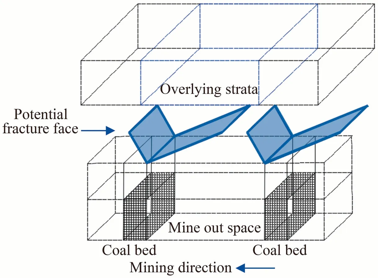
Fig.1.Schematic diagram of the double V-shaped failure pattern during the mining process.
2.Materials and methods
2.1.Experimental design and preparation
According to the theory of the trapezoidal broken model established by Xu et al.[15]and the V-shaped conceptual model of fracture evolution patterns in the overlying strata during horizontal coal seam mining process [19],the experimental samples of rock-like materials and the geometric parameters of the double prefabricated V-shaped flaws are set up,as shown in Fig.2.The dimensions of the sample are 100 mm × 50 mm × 50 mm.The geometric parameters of each prefabricated V-shaped flaw include the right flaw inclination angle (β,angle between the right flaw long side and the horizontal axis),the left flaw inclination angle(α,angle between the left flaw long side and the horizontal axis),flaw height(h),long side length(a),short side length(b),and ligament length(l).Additionally,the interpenetrated flaws are created by a thin steel sheet.The short side and the height of each flaw are the same and are fixed at 2 and 5 mm,respectively.The distance between the upper outer tip of the right one in the first V flaw(UOTRFV) and the upper outer tip of the left one in the second V flaw (UOTLSV) is fixed at 5 mm and that between the lower outer tip of the first V flaw(LOTFV)and the lower inner tip of the first V flaw (LITFV)and between the lower outer tip of the second V flaw(LOTSV) and the lower inner tip of the second V flaw (LITSV) are both 3 mm.The inclination angles of α and β for the four kinds of samples keep one angle of the two flaws in each V-shaped fissure unchanged,with a 15° increase in the other of the two flaws(Fig.2).SV of the SV5is short for separate V flaw,and the subscript represents the ligament,as shown in Fig.2.A detailed description of these tested samples with different flaw geometries is presented in Table 1.
In this experiment,fine sand (0.15–0.30 mm size) was used as the skeletal material,along with cement as the cementing material to combine the fine sand.The ratio of the material compositions including cement,fine sand,and water is 26:25:10 (by weight).In this way,not only is the brittle behaviour of the rock satisfied,but it is also more likely to experience the fracturing processes and strength variations in rock-like materials with particles distributed more uniformly,unlike natural rocks.Cement mortar samples,with mechanical properties similar to natural rocks,were applied in this research.
2.2.Experimental setup
A series of uniaxial compression tests on rock-like specimens containing double prefabricated V-shaped flaws was carried out with a rock mechanics servo-controlled testing system (Fig.3) at an axial displacement rate of 0.1 mm/min to obtain the mechanical properties.A specimen was loaded until it failed or until cracks had coalesced under uniaxial compression conditions.Each loading process was recorded by a high-speed camera (FASTCAM SA1.1)to detect new crack initiation,propagation,and coalescence,which were observed with the support of the Photron Fastcam Viewer.The FASTACM SA1 uses the latest CMOS sensor to achieve sensitivity and speeds that were previously unattainable.It is capable of capturing 5,400 full frames per second (fps) with mega pixel(1 K × 1 K) resolution.Additionally,by testing intact specimens with no flaws,the mechanical parameters and stress–strain curves of the intact specimens were obtained to compare with that of the specimens with flaws.
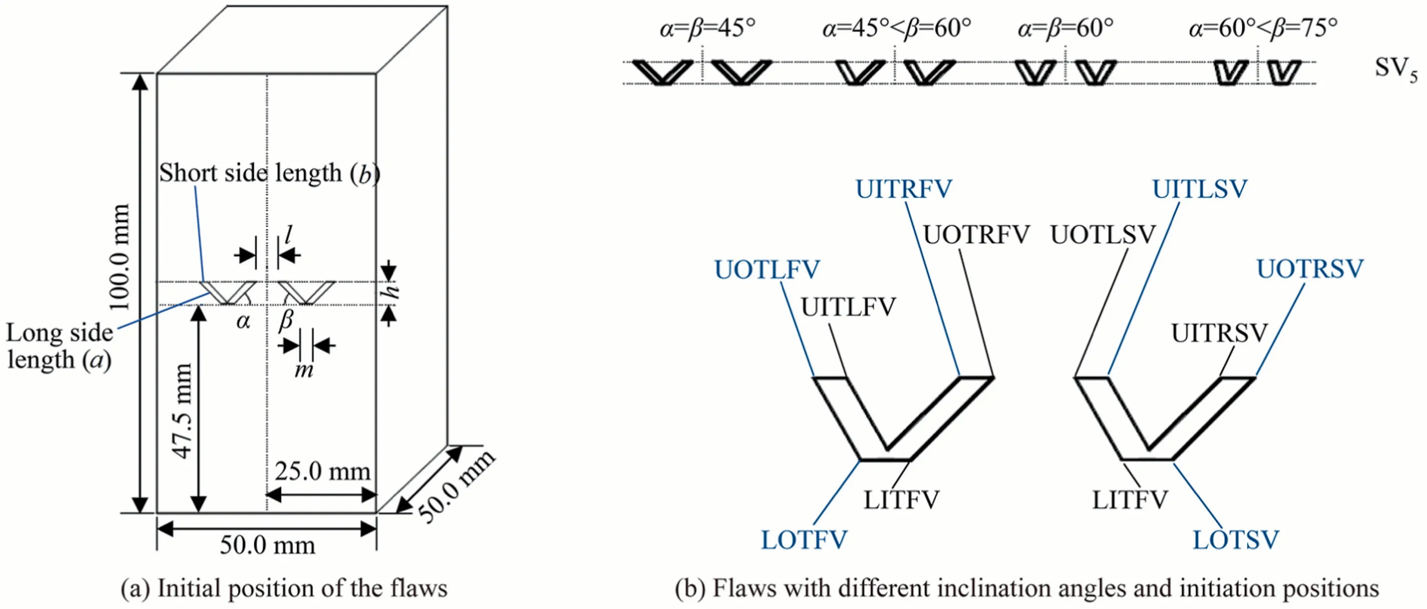
Fig.2.Schematic illustration of the initial position of the flaws and description of the flaw geometry with different inclination angles and initiation positions with respect to the double prefabricated V-shaped flaws.

Table 1Geometric parameters of the tested sample containing double prefabricated V-shaped flaws under uniaxial compression.
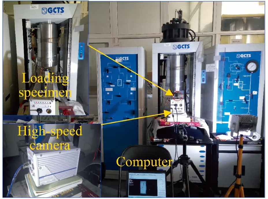
Fig.3.Testing process and main equipment used.
3.Results and discussion
3.1.Stress response of the double V-shaped flawed specimens
Fig.4 shows that the stress–strain curves of the specimens containing double prefabricated V-shaped flaws under uniaxial compression show a progressive change with increasing inclination angle.Specimens with or without flaws show an initial nonlinear deformation,mostly induced by the closure of internal particles in the material.Then,the axial stress shows an approximately linear relationship with the axial strain,clearly indicating the beginning of elastic deformation.There are no obvious stress drops before the peak strength is rapidly reached in all of the specimens;subsequently,the stress is quickly reduced to 0,and the axial deformation increases slightly,showing an obvious brittle failure.
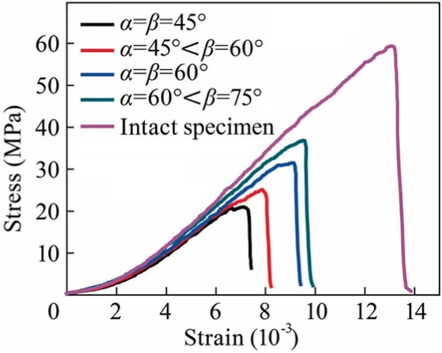
Fig.4.Stress–strain curves for the specimens containing no flaws and double prefabricated V-shaped flaws at different angles under uniaxial compression.
In this study,the initiation stress is defined as the stress when the first new crack initiation was found with the naked eye,whereas the peak stress was achieved by the rock mechanics servo-controlled testing system.Fig.5 shows the crack initiation stress presents a nearly linear changing trend generally similar to that of the crack peak stress with increasing flaw inclination angles.Furthermore,the magnitude of the former is moderately higher than that of the latter in the scope of flaw inclination angles from α=β=45°to α=60°<β=75°(the difference ranges from 2.8 to 8.23 MPa).By comparing the difference between the magnitudes of the crack initiation stress and peak stress,it can also be determined that there is a relatively greater difference at both ends of the flaw inclination angles such as α=β=45° and α=60°<β=75° and a minor difference at the middle section.The largest difference for the specimens at flaw inclination angles of α=β=45°is 8.23 MPa,which may be induced by a long transverse flaw length.The flaw length has more influence on the specimens than flaw concentration for each flaw with the same area.It is also evident that lower angles may have a larger influence on the initiation-peak stress stage for each flaw with the same area in the specimens of double prefabricated V-shaped fissures,compared to that of larger angles.Additionally,the transverse flaw length has a larger influence on the crack initiation and propagation in specimens than that of the flaw concentration on the premise of each flaw having the same area.
3.2.Peak strength,peak strain,and modulus of elasticity
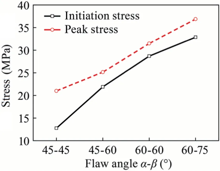
Fig.5.The crack initiation stress and peak stress versus the flaw inclination angle in the flawed specimens.

Fig.6.The effects of the orientation of the flaws with the same area on the strength and deformation parameters of specimens containing double prefabricated V-shaped fissures.
The peak strength,peak strain,and modulus of elasticity of the intact specimen are obtained from the uniaxial compression test,namely,59.39 MPa,13.85 × 10-3,and 5.73 GPa,respectively.Fig.6 shows the effects of the orientation of the flaws with the same area on the strength and deformation parameters of the specimens containing V-shaped flaws can be easily seen.The peak strength,peak strain,and modulus of elasticity of the flawed specflaws has the greatest effect on the initiation position of first tensile wing cracks.imens are obviously lower than that of the intact specimen,showing a large influence of the prefabricated V-shaped flaws on the strength and deformation parameters of the specimens.Results show that the peak strength generally presents a linear and fast growth trend with increasing flaw inclination angle (Fig.6a),whereas the peak strain presents an approximately upward convex growth trend (Fig.6b),along with a relatively increasing concave upward trend for the modulus of elasticity (Fig.6c).When the two flaw inclination angles increase from α=45°<β=60° to α=β=60° with a 15°increase in either of the two flaws,the peak strength increases linearly from 25.15 to 31.49 MPa; the peak strain has a faster increasing trend than that of the peak strength from 8.22 × 10⁻³to 9.41 × 10⁻³,together with a relatively slow increasing trend from 4.66 to 5.12 GPa for the modulus of elasticity.The development tendency of the curves in Fig.6 presents how much the peak strength,the peak strain,and the modulus of elasticity of the specimens have been influenced by the flaw inclination angles.In the scope of flaw inclination angles from α=β=45° to α=60°<β=75°,it can be easily found the lower the flaw inclination angle is,the easier the destruction of the rock specimens is.Additionally,the flaw angles have a linear effect on the strength and deformation parameters,especially for the peak strength.
3.3.Crack evolution behaviour in specimens containing double prefabricated V-shaped fissures
New cracks are always observed to initiate at the tips of nearby pre-existing flaws under an applied load,and these new cracks expand almost in the direction parallel to the maximum principal stress in the flawed specimens,leading to the coalescence of the cracks before unstable failure.Although the first macro-wing cracks in the specimen for α=β=45°initiate from the upper inner tip of the left one in the first V flaw (UITLFV) and LOTFV,those in most specimens initiate from the outer side of the first or second V-shaped flaw and usually initiate from the lower-angle flaw as tensile wing cracks,as shown in Fig.7.Fig.7 also reveals that one lower-angle flaw among the double prefabricated V-shaped

Fig.7.First macrocracks initiated from the specimens containing prefabricated Vshaped fissures with different inclination angles under uniaxial compression.
Fig.8 shows more secondary cracks along the direction parallel to the maximum principal stress are discovered in the neighbourhood between the double V-shaped flaws,which are the positions where the stress concentration or confinement increases.Additionally,the cracks development is more complicated in the specimens with α=β=45°than the others.From Fig.8,it can be seen that the crack propagation and coalescence patterns are slightly different with respect to the flaw inclination angles α and β.In the specimens with α=β=45°,the tensile wing cracks emanating from two flaw tips or near the tips continue to develop some distance along the direction parallel to the maximum principal stress,but the cracks cease after a while and a new wing crack initiates at the UOTLSV and the upper outer tip of the right one in the second V flaw (UOTRSV) of the other V-shaped fissure and becomes the main propagation crack.Meanwhile,two new cracks initiating at the UOTLSV,one at the LOTSV,and one at the UOTRFV overall develop downward along the direction parallel to the maximum principal stress,though the crack at the LOTSV first propagates along the direction of the left crack in the second V-shaped flaw.Additionally,one new crack initiating at the upper outer tip of the left one in the first V flaw (UOTLFV) propagates upward,and then a lateral crack develops inward from the edge.Only the cracks initiating at the UOTRFV and UOTLSV propagate downward and converge,and then continue to develop; these cracks are not the main ones involved with specimen failure.
In the specimens with α=β=60°,the tensile wing cracks emanating from the two flaw tips or near the tips continue to develop some distance along the direction parallel to the maximum principal stress,but the cracks cease after a while and a new wing crack initiates at the UOTRSV and LITSV of the other V-shaped fissure and becomes the main propagation crack.Meanwhile,two new cracks initiating at the UOTRFV develop upward and downward for a short distance,and there is also no crack convergence.
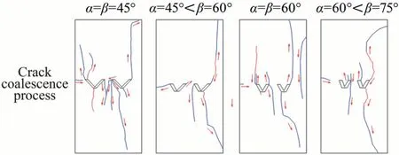
Fig.8.Sketch of the macrocrack propagation and coalescence process in the specimens containing double prefabricated V-shaped flaws with different angles under uniaxial compression(the red lines represent the initial cracks,the blue lines represent the new cracks emanating from the initial cracks,and the arrows represent the extended directions).
In the specimens at two different flaw inclination angles,including 45°<β=60° and 60°<β=75°,there is generally the same crack development trend,and there is no crack convergence.The tensile wing cracks emanating from the UOTLSV and LOTSV of a lower-angle flaw continue to develop into the boundary along the direction parallel to the maximum principal stress,becoming the main cracks of the specimen failure.Meanwhile,for the specimens with 45°<β=60°,one new crack initiating at the UOTLSV propagates downward for a short distance along the direction parallel to the maximum principal stress,and for the specimens with 60°<β=75°,one new crack initiating at the upper inner tip of the left one in the second V flaw (UITLSV) and one crack at the upper inner tip of the right one in the first V flaw (UITRFV) propagate upward for a short distance along the direction parallel to the maximum principal stress,with one new crack at the UOTRFV propagating downward for a short distance in the same way.Additionally,a lateral crack initiating from the edge propagates inward for a short distance.
As the above analysis shows,most main cracks initiate from the flaw tips with lower angles and close to the edges,and the specimens for two different flaw inclination angles have generally similar crack propagation patterns,which are the same as the specimens for the two same flaw inclination angles,and the latter has a symmetrical crack development trend.Additionally,cracks in the middle part of the two V-shaped flaws are developed.An obvious difference is presented in the crack propagation and coalescence under the effect of different V-shaped flaw inclination angles.
Fig.9 shows the main types of cracks can be categorized as wing cracks,shear cracks,secondary cracks,surface spalling,and farfield cracks.Additionally,the cracks in the experimentally failed specimens are a mixture of various crack types,the characteristics of which are not discussed in detail here.The failure of the flawed specimens is always caused by the expansion of cracks after the occurrence of crack initiation from prefabricated flaws.
The crack failure modes depend largely on the inclination angles of the two flaws in a single specimen,as shown in Fig.9.These modes can be summarized into two distinct types as described below.
(1)Type Ⅰ—the load direction-dominated mode(α=β=45°and α=β=60°).The two main cracks starting at the upper tips of the outer two V-shaped flaws develop their own trajectories upward in almost the direction parallel to the maximum principal stress,and they do not link until the failure of the specimen.There is possibly downward crack coalescence failure in the middle part of the double V-shaped flaws,and this crack develops downwards until failure of the specimen.
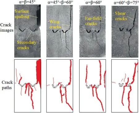
Fig.9.Ultimate failure modes of the specimens containing double prefabricated Vshaped flaws at different angles under uniaxial compression.
(2) Type Ⅱ—the mixing-dominated mode (α=45°<β=60° and α=60°<β=75°).The two main cracks starting at the tip of the one with the smaller inclination angle in the right V-shaped flaw propagate outward (one towards the upper right part of the side edge and the other towards the lower right part of the side edge),possibly because of the large flaw angle difference in the flawed specimen,which also indicates that the lateral damage is strong and is very different from the other failure modes.
From these two failure modes,it can be inferred that the new crack trajectories were mainly controlled by load direction with little influence from the prefabricated flaw inclination angle due to the symmetrical effect of bilateral inclination angle (α=β=45°and α=β=60°) in Type Ⅰ.However,in Type Ⅱ(α=45°<β=60°and α=60°<β=75°) the new crack trajectories were controlled by the lower-angle flaw of exterior edges together with the loading direction.And there is no increasing inclined trend of crack failure in the direction of the lower-angle flaw with decreasing flaw inclination angles,supposing that there is a mixed influence from the lower-angle flaw and loading direction.Relatively speaking,there is a bigger influence on the crack trajectories of the specimens from the flaw with increasing inclination angels.
3.4.Characteristics of surface cracks in the specimens at ultimate failure
ImageJ is an image processing and analysis software,allowing the analysis of the areas,lengths,and angles.In this study,this software was used to obtain binary images of the surface cracks in the ultimate failure modes of all specimens and then identify the surface crack areas (crack area > 2 mm2) and their inclination angles.Fig.10 shows that the horizontal axis represents the dip angles of the identified surface cracks,and the vertical axis shows the percentage of the crack area at different dip angles accounting for the total surface crack areas.And the displayed flaw angles are the angles between all identified crack directions and the left horizontal direction; for example,the dip angle of the prefabricated flaw,α=60°<β=75°,is presented as displayed flaw angle of 120° and 75°,respectively.
In Fig.10,for the specimens with α=β=45° (displayed flaw angle,135° and 45°),the crack dip angle focuses on the range of 90° and 0°–10°,and the percentage of the former is much larger than that of the latter,showing that the direction of the surface cracks mainly develops in the load direction.For the specimens with α=45°<β=60°(displayed flaw angle,135°and 60°),the crack dip angle focuses on the range of 80°–100°and 0°–10°,and the percentage of the former is much larger than that of the latter,both of which are much larger than the range of 50°–60°,indicating that the direction of the surface cracks mainly develops in the load direction,and the lateral direction is in a secondary position.For the specimens with α=β=60° (displayed flaw angle,120° and 60°),the crack dip angle focuses on the range of 85°–100°,whose percentage is much larger than that of 60°–70°,indicating that the direction of the surface cracks mainly develops in the load direction,and yet the load direction has a much larger influence on the dip angle of these cracks than the flaw inclination direction.For the specimens with α=60°<β=75°(displayed flaw angle,120°and 75°),the crack dip angle focuses on the range of 85°–100°and 165°–170°,and the percentage of the former is slightly larger than that of the latter,indicating that the direction of the surface cracks still mainly develops in the load direction,and the lateral direction is second to the load direction.These results suggest that the distribution of the main crack dip angle in the specimens at ultimate failure containing double prefabricated V-shaped flaws is mainly subject to the loading stress,and the prefabricated flaws have little influence on the distribution of the dip angle.

Fig.10.Crack binarization images and the distribution of the dip angle of the main cracks in the ultimate failure modes of the specimens containing double prefabricated Vshaped flaws under uniaxial compression.
4.Conclusions
(1) From a series of uniaxial compression experiments conducted in this study,it can be found that most of the first macrocracks initiated from the outer side of the first or second V-shaped flaw and always from a lower-angle flaw as the tensile wing cracked.The specimens for two different flaw inclination angles had generally similar crack propagation patterns,and the specimens for two identical flaw inclination angles were the same,along with the cracks that developed in the middle part of the two V-shaped flaws.
(2) The crack failure modes depended largely on the inclination angles of the two flaws in a single specimen.Additionally,on the basis of the analysis of the characteristics of surface cracks in the ultimate failure modes of the specimens,it determined that the distribution of the main crack dip angle in the specimens at ultimate failure containing double prefabricated V-shaped flaws was mainly controlled by the loading stress,with little influence from the prefabricated flaws.
(3) Therefore,although this kind of prefabricated flaw did not necessarily induce its ascending coalescence,the trend of coalescence became more pronounced with the increase in the flaw dip angle,especially for specimens with different flaw dip angles.More studies are needed to gain a better understanding of the complex process of double V-shaped prefabricated fissure development under the influence of coal mining.
Acknowledgements
This work was supported by the financial support of the National Natural Science Foundation (Grant Nos.41572244,41807283,and 51804184),the Natural Science Foundation of Shandong Province (Grant No.ZR2015DM013),the Scientific Research Foundation of Shandong University of Science and Technology for Recruited Talents (Grant No.2017RCJJ031),Open Fund of State Key Laboratory of Coal Resources and Safe Mining (Grant No.SKLCRSM19KFA10),and Science and Technology Research Directive Plans of China National Coal Association (Grant No.MTKJ2018-263).Sincere gratitude is expressed to the reviewers for their many helpful comments and constructive criticisms.
杂志排行
矿业科学技术学报的其它文章
- Identification of digital technologies and digitalisation trends in the mining industry
- Experimental and theoretical investigation on mechanisms performance of the rock-coal-bolt (RCB) composite system
- Creep characteristics of coal and rock investigated by nanoindentation
- Comparative evaluation of different statistical tools for the prediction of uniaxial compressive strength of rocks
- A rapid and accurate direct measurement method of underground coal seam gas content based on dynamic diffusion theory
- Optimization of gob ventilation boreholes design in longwall mining
