Experimental and theoretical investigation on mechanisms performance of the rock-coal-bolt (RCB) composite system
2020-12-20GenshuiWuWeijianYuJianpingZuoShaohuaDu
Genshui Wu ,Weijian Yu ,Jianping Zuo,*,Shaohua Du
a School of Mechanics and Civil Engineering,China University of Mining and Technology-Beijing,Beijing 100083,China
b State Key Laboratory of Coal Resources and Safe Mining,China University of Mining and Technology-Beijing,Beijing 100083,China
c School of Resource & Environment and Safety Engineering,Hunan University of Science and Technology,Xiangtan 411201,China
d School of Resources and Safety Engineering,Central South University,Changsha 410083,China
ABSTRACT For coal mines,rock,coal,and rock bolt are the critical constituent materials for surrounding rock in the underground engineering.The stability of the ‘‘rock-coal-bolt” (RCB) composite system is affected by the structure and fracture of the coal-rock mass.More rock bolts installed on the rock,more complex condition of the engineering stress environment will be (tensile-shear composite stress is principal).In this paper,experimental analysis and theoretical verification were performed on the RCB composite system with different angles.The results revealed that the failure of the rock-coal (RC) composite specimen was caused by tensile and shear cracks.After anchoring,the reinforcement body formed inside the composite system limits the area where the crack could occur in the specimen.Specifically,shearing damage occurred only around the bolt,and the stress-strain curve presented a better post-peak mechanical property.The mechanical mechanism of the bolt under the combined action of tension and shear stress was analyzed.Additionally,a rock-coal-bolt tensile-shear mechanical(RCBTSM) model was established.The relationship (similar to the exponential function) between the bolt tensile-shear stress and the angle was obtained.Moreover,the influences of the dilatancy angle and bolt diameter of the RCB composite system were also considered and analyzed.Most of the bolts are subjected to the tensile-shearing action in the post-peak stage.The implications of these results for engineering practice indicated that the bolts of the RCB composite system should be prevented from entering the limit shearing state early.
Keywords:Thin coal seam Coal and rock roadway Bolt Tension-shear failure‘‘Rock-coal-bolt” composite system
1.Introduction
In southern China,there are abundant reserves of inclined and gently inclined thin coal seams in coal mines.Statistically,inclined seams with the angle above 35° account for more than 20% of the total coal resources in China [1–4].In the mining process of such inclined thin coal seams,roadways are usually constructed between the coal seam and rock mass [5].Engineering practice shows that the instability and failure of rock-coal composite roadways(RCCRs)mainly depend on the development and expansion of joints or fissures in coal-rock mass.Moreover,the structural plane of fissured rock mass determines the mechanical properties of rock mass [6–12].Over the past century,the rock bolt anchoring technology has gradually occupied a critical position in large-scale rock engineering and geotechnical engineering [13–15].The rock bolt can improve the self-strength and bearing capacity of the anchoring target rock mass;moreover,it can well resist different degrees of impact failure of hard rock under static and dynamic loads,high stress,and high strength[16,17].Therefore,the use of rock bolt as a supporting and reinforcing method has become increasingly mature in most underground mines and many other large-scale projects (bedding slope anchoring,dam,composite layered tunnel excavation,and underground chamber,etc.)around the world[18–22].The rock bolt anchoring in large structural planes e.g.coal and rock mass can show a good reinforcement effect[23].However,the deformation between the surrounding rock and the anchorage body of many thin coal seam roadways is not harmonious.Thus the roadways are liable to cause uneven shrinkage and extrusion damage.Rock-coal (RC) composite systems are unstable from the coal body to non-linear damage,and instability of the whole system seriously threatens personal safety and restricts production efficiency.
Laboratory and field test results show that if the interaction mechanism between rock bolt and rock mass is complicated,its mechanical behavior modeling is also complicated.Therefore,the interaction among rock,fissure,grouting,and bolt should be considered [24–29].Currently,many scholars mainly focus on the following aspects of rock anchoring technology [30–32]:(1)the innovation of bolt anti-corrosion technology,(2) development and application of high bearing capacity anchoring system,(3) study and reveal of the long-term working performance of the bolt,and (4) research on distribution characteristics of bolt bond stress under tension-shear and innovation of mechanism for improving the load transfer of anchor.More research results have been achieved in the first three aspects,while the research on the distribution characteristics of tensile-shear stress of anchor joints and fractured bolts is still in the exploratory stage.Under the action of tension-shear,the calculation of the resistance between the rock bolt and the RC composite system is complicated,which is mainly reflected in the following two aspects:(1) The axial force and shear force of rock bolt are affected by the shape and geometric mechanical parameters of the bolt,the mechanical properties of coal as well as rock mass,and the structural fracture plane.(2) The bolt is acted by axial stress and transverse shear force; thus,it cannot be analyzed separately [33–36].In recent years,many scholars have paid great attention to the mechanical properties and material parameters of rock bolts.Stille et al.considered different bolt properties,and the closed form elastic-plastic analysis solution of grouting bolt was given [37].Cai et al.derived the analytical solution of rock bolt describing interaction based on the shear lag model [38].Ma et al.put forward an analysis model of rock bolt,which could predict the shear performance of bolt by comprehensively considering the pre-tightening force,axial force,interfacial-bonding stress between the bolt and cement slurry,and the transmission force acting on bolt transversely [39].Although many theoretical and numerical analysis models have been proposed to describe the mechanical response of the bolt and rock joint subjected to shear load [40–42],most of them focus on a specific part of the bolt for independent research and often ignore the mechanical characteristics of the integral anchoring of rock bolt and rock; few can successfully predict and explain the complex tensile and shear forces generated in the rock bolt and anchor body.Most scholars tend to pay more attention to the study of the RC composite system’s mechanical behavior,judging from the current research content.
For the thin seam coal and rock roadway engineering,the surrounding rock is usually composed of the so-called ‘‘rock-coalbolt”(RCB)composite structure.Many researchers do not take into consideration the stress characteristics of the RCB composite system under complex stress states [43–46].In complex geological conditions,the interaction mechanism between the bolt and anchored coal and rock is quite different.However,under the condition of thin coal seam mining,the coupling behavior between the coal,rock mass,and support structure has special nonlinear deformation characteristics.Therefore,coal,rock mass,and supporting structure cannot be studied separately; on the contrary,it should be considered as a whole coupling ‘‘coal-rock-bolt” system for analysis,so as to fully grasp the mechanical characteristics of this kind of composite rock mass and the support structure.In this paper,therefore,a series of uniaxial compression tests on inclined RCB composite specimens are carried out.According to the mechanical relationship between the rock bolt and the inclined coal-rock composite structural plane,the rock-coal-bolt tensileshear mechanical(RCBTSM)model of the bolt through the inclined coal-rock composite structural plane under tension and shear is established and further verified.
2.RC/RCB composite specimens preparation
A large number of thin coal seam resources are distributed in southern China.Fig.1 illustrates the failure of the No.5126 mining gateway in Zhoujing coal mine in Baise City,Guangxi Province,China.During the roadway excavation,due to the disturbance of excavation stress,the rock bolt anchored in the coal of the thin coal seam RCCRs has shown a slight expansion deformation.The rock bolt restrains the formation of anchor solids between inclined coal and rock layers,internal cracks,and structural planes,making the coal and rock mass form a new stress equilibrium state.As shown in Fig.1a,once the anchorage fails,the upper rock and coal will produce non-linear extrusion deformation.When the coal seam is mined,due to the stronger mining superposition stress of the adjacent working face,the bolt in the coal and rock mass is easy to fail,resulting in the large irregular deformation (similar to step deformation) of the coal and rock mass (Fig.1b).No matter whether the coal seam is in the upper part of the rock mass or the rock mass is in the upper part of the coal seam,the nonlinear and non-uniform deformation failure will occur when the roadway is excavated.Therefore,based on the engineering characteristics of thin seam RCCRs,the coal and rock were sampled on site.The standard specimens were prepared and uniaxial compression tests (UCTs) were carried out.
The rock sampling site is a thin coal seam mine in Changde City,Hunan Province,China(the buried depth is 500 m).Before the test,the scanning electron microscopy (SEM) was carried out on coal and sandstone (Fig.2).After 500 times magnification,the coal micro morphology shows the typical wavy distribution,and some primary fractures can be observed.In contrast,the micro morphology of sandstone is smooth and flat without any visible micro cracks.Therefore,the micro integrity of sandstone is better than that of coal.
The inclined RC composite specimens are composed of coal and sandstone.The volume ratio of rock to coal is 1:1,and the RC composite specimens with the angle of 0°,15°,30°,and 45°,are denoted as RC-0°,RC-15°,RC-30°,and RC-45°composite specimen,respectively.The specimens are strictly carried out with the International Society of Rock Mechanics (ISRM) standard [47],and the length-to-diameter ratio is 2:1 (the diameter φ is 50 mm and the length h is 100 mm).There is not only a mechanical interlocking force formed by rock bolt restraint between the fracture structural planes of the RC composite system in the actual roadway,but also the cohesive force between the structural planes of the coal and rock system.Therefore,in order to restore the actual mechanical properties of the RC interface as much as possible,the authors chose to treat and paste the RC interface with marble glue,as shown in Fig.3.Before the experiment,the authors first selected the same rock sample and coal sample with good homogeneity,and removed the rocks with a significant difference for combination after the acoustic test,so as to avoid errors caused by the sample.A unified adhesive quantity was also used to reduce the error of test results caused by the uneven adhesion.The test loading equipment is the RMT-150C electro-hydraulic servo rock mechanics test system developed by the Institute of Rock and Soil Mechanics,Chinese Academy of Sciences.The loading rate is 0.005 mm/s constantly (displacement-loading control) until the specimens are entirely destroyed.Some physical parameters of the specimens are shown in Table 1.The diameter error of all test combination specimens is 50±1 mm,and the height error is 100±2 mm.Additionally,each group of tests was repeated three times to improve the accuracy of the test.

Fig.1.Typical failure behavior of RCCRs and stress state of rock bolt.

Fig.2.SEM apparatus and SEM results of coal and sandstone.
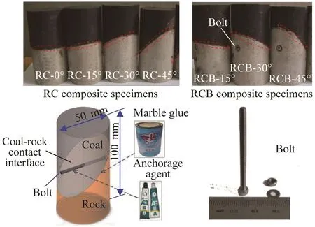
Fig.3.Partially inclined RCB composite specimen.
The RCB composite specimens are set up with three combination angles of 15°,30°,and 45°,denoted as RCB-15°,RCB-30°,and RCB-45° composite specimen,respectively,that is,the bolt is anchored along the full-length of both horizontal ends (see Fig.3).Horizontal RC composite specimens (RC-0°),sandstone,and coal specimens are used as referenced specimens.The anchoring process of the RCB composite specimens is as follows.Firstly,a drill with a 3 mm diameter was used to have the same size bolt hole along the horizontal direction.After that,threaded steel rock bolts were passed through the inclined surfaces of coal and rock,and AB glue was used as the anchoring agent for full-length anchoring.The specific mechanical parameters of the bolts are shown in Table 2.
3.RC/RCB composite specimens UCT results
3.1.Failure pattern
Fig.4a shows the typical failure macroscopic crack distribution of the RC composite specimens.The failure cracks of the RC-0°and RC-15° composite specimens are mainly distributed in the coal,and a small number of cracks developed in the rock,mainly in the tension failure of the coal.The macro-cracks of RC-30° and RC-45° composite specimens penetrate the coal and rock,mainly the combined failure of tension and shear.A slight slip on the coal-rock contact surface of the RC-45° composite specimen can be observed.The cohesive force between the coal-rock contact surfaces is generally more significant than the failure force; thus,the slight slip is not the principal reason for the primary instability failure of the specimen.There are two complicated principal failure planes in all specimens,and the fracture surfaces exist in the form of intersections.
Different from the large-scale rock bolt direct shear test[48,49],the RCB composite system in this test is a special combination system.The coal and rock interface has a particular strength of the cohesive force.Under the action of external load,coal,rock,and bolt play their respective roles to maintain the system balance.Fig.4b illustrates the typical failure of the RCB composite specimens.Through thermal imaging technology,the characteristics of tensile and shear cracks in the rock fracture process can be distinguished.The specific method can be referred to [50].The tensileshear cracks are developed in the coal of the RCB-15° composite specimens.The RCB-30°and RCB-45° composite specimens jointly formed a similar X-shaped conjugate shear and tensile failure in coal and rock.The two principal shear planes do not form an intersection due to a bolt-reinforcement anchorage zone.The coal-rockbolt anchorage body limits the area where the normal specimen crack could occur.The damage zone is mainly distributed on both sides of the bolt anchorage zone.It could be noted that the failure and instability of small-angle (i.e.RC-0° and RC-15°) composite specimens,as well as RCB-15° composite specimens first occurred on the relatively weak coal.Since the combined surface’s inclination angle is small,the stress acting on the structural surface of the coal rock body is relatively uniform.After the angle is increased(>15°),once the coal begins to resist tensile-shear fracture,local stress concentration will be formed on the contact surface of coal and rock and the bolt anchorage body,mainly for the tensileshear composite stress action.As a result,both the coal and the rock have tensile damage and shear failure.Under this complex condition,the strength of the inclined RCB composite specimen is influenced by the strength of the coal,the rock,and the rock bolt.
Under the external load,the RC composite system first cracks in the coal,and then gradually develops to the composite failure ofthe coal and the rock.The bolt strengthening effect fails after the ultimate peak strength.Fig.5 shows a sketch map of the coal failure in the RC and RCB composite specimens depending on the statistics of UCT.It can be observed that the cracks mainly run through the middle of the coal,specifically,the cracks are mainly tensile cracks developed on both sides,and shear cracks are a secondary failure.The RCB composite specimen is only fractured in a small range around the coal body.Therefore,the bolt can restrain the development of irregular fractures in the coal.

Table 1Physical parameters of specimens (average).

Table 2Specific mechanical parameters of the bolt.
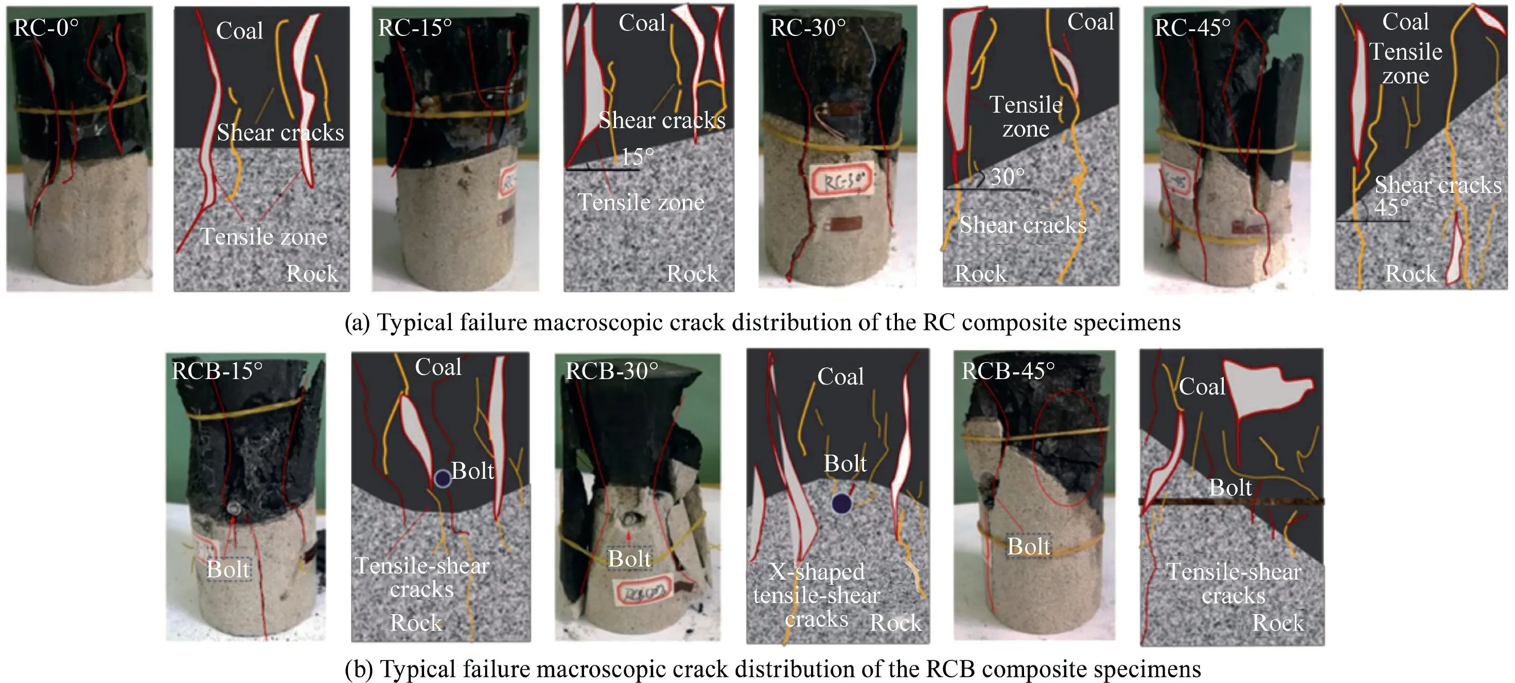
Fig.4.Failure mode and sketch of RC/RCB specimens with different combination angles.
3.2.Mechanical characteristics
Fig.6 shows the stress-strain curve of the intact coal and sandstone specimen.It can be observed that sandstone and coal specimens show a typical brittle failure.The mean uniaxial compressive strength (UCS) of sandstone specimens is 37.06 MPa.Compared with sandstone specimens,the internal defects of coal are quite different,and the mean UCS is 20.04 MPa.

Fig.5.Sketch of bolt mechanics mechanism of the RC and RCB composite system.
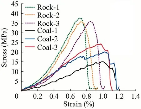
Fig.6.Stress-strain curves of intact coal and sandstone specimens.
Fig.7a and b show the stress-strain curve of the RC and RCB composite specimens,respectively.The curves of RC and RCB composite specimens have undergone compaction,linear elasticity,and post-peak stages,which are the same as the curve trends of intact sandstone and coal specimens.The RC composite specimens have slightly multi-peak fluctuation in the post-peak stage,which results in a stepped stress drop (Fig.7a).The main reason is that the mechanical properties of the RC composite specimens are significantly different with those of rocks.When the loading is near the peak,especially in the post-peak stage,a sizeable macroscopic fracture occurs at the critical point of the coal-rock interface,and the elastic deformation energy is released.It can be seen in Fig.7 that the stress-strain curves before the peak of the RC and RCB composite specimens are consistent without any significant differences.However,after the peak of the curve,there are three modes of failures of RC/RCB composite specimens:(1)only coal failure,(2)only rock failure,and (3) both coal and rock composite failure.From the results of the damage of the specimens (Fig.4),most of the failures are the composite failures of coal and rock.It is worth noting that unlike typical intact brittle rocks typical test results,the inclined RC composite specimens have multi-peak properties after the peak and the mechanical properties are complicated.

Fig.7.Stress-strain curves of RC and RCB composite specimens.
Generally,the bolt tensile-shear could occur in the post-peak stage of the RC/RCB composite specimens.Therefore,the RCB composite system analysis cannot just consider the effect of one shearing force.However,the resistance model of the bolt under the condition of the tensile-shear should be considered comprehensively.This model needs to take into account the angle of the coal-rock contact surface,mechanical properties of the bolt,and mechanical differences of the coal and rock to describe and guide the mechanical design of the RCB composite system.Therefore,this model build of the RCB composite system is detailly described in Section 4.
4.Rock-coal-bolt tensile-shear mechanical (RCBTSM) model
4.1.Mechanical properties of anchor bolt
In engineering practice,the interface between the composite stratum(coal and rock) can be assumed as a special fracture combination surface.The reinforcement effect of the bolt is mainly to improve the shear resistance and deformation restraint capability of the coal-rock structural plane,which strengthens the stability of the RC composite system.In the stage of slight deformation of anchor bolt,the anchoring effect of the bolt and RC composite system is mainly manifested in the following three aspects (see Fig.8a).
Firstly,the bolt will resist the tensile-shear stress when there is a deformation or deformation trend in coal or rock mass.Afterward,the axial stress of bolt increases the shear resistance of the structural plane along with the normal component of the RC contact plane.
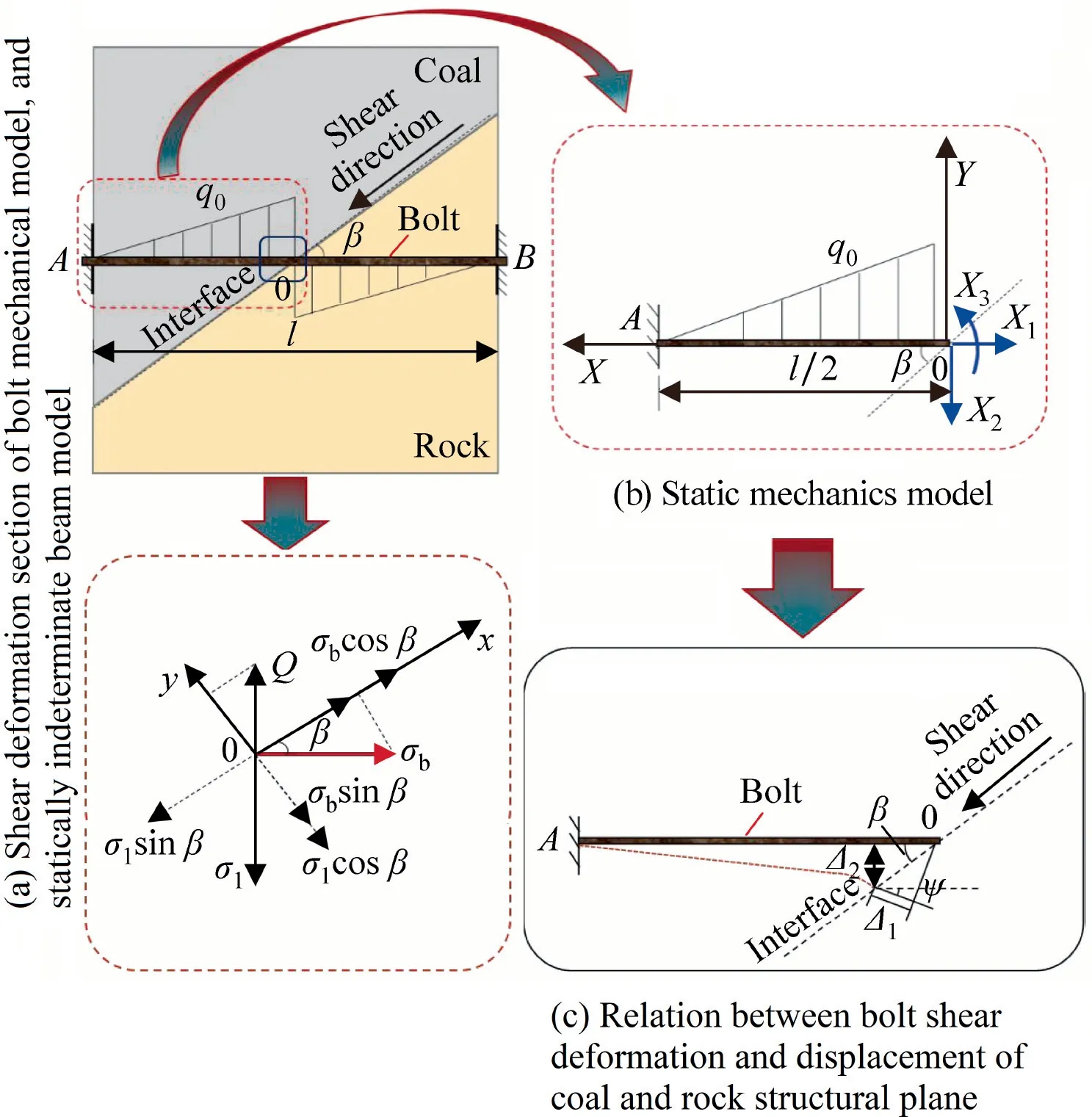
Fig.8.Stress analysis of RCB composite system.

where σbis the axial stress of the bolt;σ′bthe normal component of σb;β the angle between the contact surface of the coal and rock and the horizontal bolt; and φ the internal friction angle.
Secondly,the component σ′′bof the axial stress of the bolt(along the direction of the RC contact plane) directly provides the anti-sliding stress.

The total anti-sliding stress σbN,provided by σbat the coal-rock interface,can be obtained by Eqs.(1) and (2).

Thirdly,the relative displacement of the coal and rock contact planes will make the bolt resist tension-shear stress.Due to the rock bolt has a certain initial stiffness,the transverse resistance shear stress σbQof the bolt will limit the relative deformation between the contact planes of inclined RC composite system.

where σQis the normal shear stress perpendicular to the axial stress of the bolt.
4.2.Model establishment
There are two failure modes of bolts on the RC structural plane for anchoring different types of rocks.One exists in the relatively hard rock mass,the anchor bolt at the fracture surface shows the tensile-shear failure under the combined action of axial force and shear force.Ferrero [51] believed that the UCS of hard rock subjected to tensile-shear failure should not be less than 50 MPa.It should be pointed out that from the test results in Section 2,the combined failure of the bolt under tension and shear also exists in the RCB combined system.This type of combined rock properties is complex and it is not suitable to use UCS as an evaluation index.The other mode is that when the bolt is anchored in the weak rock mass or coal,the tension-bending failure occurs in the range of 2–4 times bolt diameter on both sides of the structural fracture plane.Besides,when the rock is fragile,the lateral shear resistance of the bolt is small,and the bolt presents a typical pull-out failure [21,52].This section mainly discusses the bolt tensile-shear mechanism.
Under the action of tension and shear stress,the length of the bending deformation section of the bolt is generally several times of the bolt diameter.The stress and deformation are antisymmetric distributed along the structural plane.Based on this,the bending deformation section at the sliding surface of the full-length bonded bolt can be regarded as a beam with fixed ends at both ends.The structural mechanic analysis is performed by considering the deformation section of the bolt,and the static structure at both ends is fixed.The linearly distributed load provided by the host material along the transverse deformation section of the bolt depends on the bolt and the host material’s geometrical and mechanical parameters,which should be very complicated.Therefore,the linearly distributed load is often simplified by researchers.For example,a trapezoid distribution and a triangular distribution were applied by many scholars [53–55].In this case,it can be assumed that the shear-deformed section of the rock and coal has a triangular distribution of the lateral restraint load of the bolt[54],as shown in Fig.8a.
The two ends of the bolt are subject to the same binding force,and the load is an antisymmetric distribution,which belongs to the statically indeterminate structure model(Fig.8b).In order to simplify the calculation,the A0 segment of the bolt (Fig.8b) can be taken for internal force analysis.The statically indeterminate problem of the transverse shear deformation section is transformed into the statically determinate beam problem,as shown in Fig.8b [21].
The axial displacement,deflection,and rotation angle are defined as Δ1,Δ2,and Δ3at the point 0 of the bolt.Based on the structural mechanics theory,the bolt force method equation can be established.

where δijis the compliance coefficient (i,j=1,2,3),which is the displacement along the Xidirection generated by the unit force Xj=1;X1,X2,and X3the axial force,shear force,and bending moment at the bolt point 0,respectively;Δiqthe displacement in the Xidirection caused by the load.The compliance coefficients δijand Δiqcan be obtained by the force method equation as follows.

where l is the length of the bolt deformation section; E the elastic modulus of the bolt; A the cross-sectional area of the bolt; I the moment of inertia of the bolt; G the shear modulus of the bolt; q0the load concentration of the bolt deformation section; and k the uneven distribution coefficient of the shear force of the bolt section,and k can be set as 10/9 for the circular section anchor.
The point 0 in Fig.8 is the reverse bending point of the transverse shear deformation section of the bolt.In the small deformation stage,the shear force at the point 0 of the bolt equals zero.Therefore,substituting X3=0,X2=0,and Eqs.(6) and (7) into Eq.(5),the following equation can be obtained.
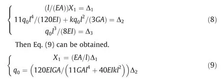
As shown in Fig.8,the force axis is established,and the load distribution of the bolt,Qq,can be obtained.

According to the material mechanics and structural mechanics,the equations of axial force and shear force at the point 0(l=1/2l)of the bolt,N0and Q0,can be obtained.

In the deformation stage of the bolt,the dilatancy(shear shrinkage) of the structural plane of the RCB combined system is taken into account.Let the dilatancy angle of the coal-rock contact face be ψ.The established coordination relationship between the sliding deformation of the bolt and the sheared structural plane of the RCB combined system is shown in Fig.8c.Under the action of the internal and external shear load of coal and rock contact plane,the following displacement equation is satisfied.

The simultaneous Eqs.(11)–(13)can be used to obtain the relationship between bolt axial force N0and shear force Q0of the RCB combined system.

According to the principle of material mechanics[53],the stress equations of axial force and shear force at bolt section 0 is as follows.

where SQis the cross-sectional area of the shear force at the point 0 of the bolt,and for the circular anchor SQ=ξA,where ξ=0.1 is the bolt stress section coefficient.
From Eqs.(3) and (4) and Eqs.(15) and (16),the equation of shear stress contribution ratio provided by the bolt to the RCB combined system structural plane can be obtained.

where K=(11GAl2+40kEI)SQ/(30GIA) is the correlation constant of the section characteristics of the bolt.
The tensile-shear resistance ratio of the bolt in Eq.(17) is related to the combination angle of the coal and rock,the crosssectional coefficient of the bolt,and the dilatancy angle.These parameters are of great significance for evaluating the stability of the RCB combined system.However,the rock-coal-bolt tensileshear mechanical (RCBTSM) model does not consider the anchoring angle between the bolt and the contact plane of the RCB combined system.The selection of the anchoring angle is also essential.Therefore,the prediction and optimization angle of the bolt of the RCB combined system will be further discussed.
4.3.RCB combined system anchoring optimization model
Before analyzing the RCB combined system optimization model of the bolt,the following assumptions are made:(1) The strength of RC combined system obeys Mohr-Coulomb criterion.(2) The RC combined system structural plane obeys Mohr-Coulomb criterion.(3) The RC combined system is isotropic and homogeneous.For intermittent jointed rocks containing both microcracks and macroscopic cracks,the damage variables can be calculated by coupling the damage caused by these two types of defects [55].
Under the condition without bolt anchorage,the normal stress σ and shear stress τ on the structural plane of the RCB combined system can be expressed by the first and third principal stresses[56,57].

where σ1is the maximum principal stress(axial stress);and σ3the minimum principal stress (confining pressure).
Assuming that the shear strength of the structural plane between the coal and rock follows the Coulomb criterion [57–59],the following can be obtained.

where c and φ are the cohesion and internal friction angle of the RC composite system,respectively; and σ and τ the normal and shear stress on the structural plane of the RC combination,respectively.
By substituting Eq.(18) into Eq.(19),the failure conditions of coal and rock structural planes can be obtained.

where subscript ω represents the RC structural plane parameter.
After the RC combined system is supported by bolts,it is assumed that the designed anchoring angle between the bolts and the structural plane of coal and rock is θ.The additional increment of principal stress and shear stress (σbaand τba) exerted by the bolts on the structural plane of the RCB combined system are as follows.

where n ≥1 is the number of bolts;and 0°<θ<90°the acute angle between the bolt and the RC combined system structural plane,and θ=β when the bolt is horizontally anchored.
By combining Eqs.(18),(19),and(21)together,the equations of the total principal stress and shear stress on the RC combined system structure surface after bolt anchoring are obtained.

When small deformation and sliding failure occur on the RCB combined system structure surface,the shear action of the bolt can produce maximum additional shear stress σbQ.The shear strength of the RCB combined system can be obtained.

where σbQ=nσQsinβ -nσQcosβtanφ.
By substituting Eq.(22)into Eq.(23),the Coulomb strength criterion of the RCB combined system structural plane expressed by the first and third principal stresses is obtained.

According to Eqs.(21) and (25),the compressive strength Δσbaof the RCB combined system structural plane can be obtained,i.e.the contribution value of the bolt,as shown in the following equation.

Eq.(25)is a variation law model of the strength increase of the RC combined system considering the anchor angle of the bolt,i.e.the optimal anchoring angle prediction model of the bolt.
5.Influencing factors of the RCBTSM model
5.1.Bolt resistance contribution
In order to have a better comparative analysis,a single bolt(n=1) was selected as an example in this section.The bolt,the RC interface,and the RC combined system are regarded as an intact‘‘rock-coal-anchor”combination body.The internal friction angle φ is 30°,the elastic modulus E=200 GPa,the shear modulus G=75 GPa,the bolt diameter D=20 mm,and the length of the bolt deformation section l=3D.The moment of inertia of bolt I=πD4/64[20].The shear modulus of the bolt,G,has the following relation with the elastic modulus E.

where μ is the Poisson’s ratio of the bolt.
The self-developed Matlab program can be utilized to obtain the variation of the bolt resistance contribution rate(σbQ/σbN)and the dilatancy angle (β),as shown in Fig.9.The relationship between the contribution ratio of bolt resistance and the angle of RCB combined system contact face in the RCBTSM model shows a ‘‘similar to exponential function” relationship,which can be divided into the following two stages:(1) Stage I (0° < β < 30°),the axial stress of the bolt plays a significant role,while the shear stress hardly acts.(2) Stage Ⅱ(30° < β < 80°),the bolt starts to be subjected to shear stress,and then increases continuously.Taking the contribution rate of the bolt resistance of the RCBTSM model as one critical value(i.e.the axial force and shear force of the bolt are consistent),the result shows that the larger the dilatancy angle is,the smaller the contribution rate of anchor resistance will be in Stage Ⅱ.In other words,the bolt resistance contribution value with larger dilatancy angle will enter the shear state earlier with the increase of the angle (β=71°,72°,and 75° when ψ=0°,3°,and 5°,respectively.).The law of the bolt resistance ratio and the angle shows that the shear contribution ratio of the bolt in the whole stage increases with the increase of the angle of the RCB combined system contact surface.It should be noted that the inclination angle β=30° is the occurrence point of the shear stress in the RCBTSM model corresponding to different dilatancy angles.At that point,the bolt begins to be subjected to shear stress and increases with the increasing angle.When the angle of the RC combined system contact face is less than that of this point,the axial stress of bolt plays a crucial role in the stability of coal and rock.When the angle is higher than that of this point,the bolt will be subjected to tensile-shear stress.It is worth noting that in practical applications,the bolt and anchored coal and rock mass should be prevented from reaching this combined limit state of tension and shear.
Fig.10 shows the relationship between the resistance contribution ratio of conventional bolts with different diameters and the contact face angle.The increase of bolt diameter also changes the β value corresponding to the bolt resistance contribution ratio value σbQ/σbN=1 in the model (β=58.0°,61.8°,64.0°,and 69.9°when D=16,20,22,and 30 mm,respectively.).It is demonstrated that the larger the bolt diameter is,the smaller the ratio of axial effect to shear effect will be.That is,the larger the bolt diameter is,the later it will enter the shear state.It is easy to see that when the critical value of the bolt resistance contribution ratio of the bolt diameter D=30 mm is 1,the anchoring angle can reach 71.9°,which is larger than that of the small-diameter bolt.Therefore,the large-diameter bolt can prevent the bolt from entering the final failure state of tension and shear prematurely,and also be used in the RC combined system under more complicated conditions.

Fig.9.Relationship between surface angle,dilatancy angle,and the bolt resistance ratio of the RCB combined system.
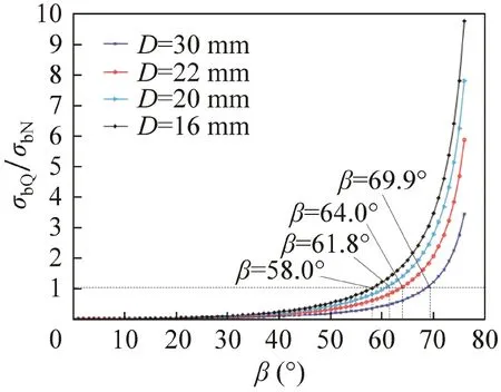
Fig.10.Relationship between the resistance contribution ratio of conventional bolts with different diameters and the contact face angle (ψ=5°).
In order to analyse the influence of the number of bolts on the strength of rock fracture structural plane,Li et al.[60] carried out laboratory tests and numerical analysis on different jointed rock masses.Taking the test results of rock mass without bolt as an initial reference,the increment of rock mass strength (bolt contribution value) in the condition of 45° anchoring angle,UCT (σ3=0,β=60°) was calculated,as shown in Fig.11.The results show that when the angle of anchorage is less than 16°,the difference of UCS between single anchor,double anchor,and the triple anchor is small(<1.2 MPa).When the anchoring angle is increased(θ>16°),the more anchor bolts installed,the more obvious effect of increasing the UCS of rock structure plane is.The anchoring angle θ=45°is the optimal anchoring angle in this test condition.Similar to the test results,in the same anchoring system,the number of bolts does not change the optimal anchoring angle.However,the number of bolts will change the contribution value of bolts.That is,as the number of bolts increases,the bolt contribution value also increases.Therefore,the theoretical results are in good agreement with the experimental results.
5.2.Optimal anchoring angle and model verification
The law of different anchoring angles on the strength of the RC combined system contact face (contribution value of the bolt) is shown in Fig.12.The trend of the bolt contribution curve is similar to a quadratic parabola with a downward opening.It can be seen in Fig.12 that:(1)In the region of θ<38°,with the increase of anchoring angle θ,the increment of compressive strength Δσbaof the RCB combined system contact surface increases.(2) In the region of θ > 37°,with the increase of anchoring angle θ,the compressive strength Δσbaof the contact surface of the RCB combined system decreases.It can be concluded that there is an optimal anchoring angle between the bolt and the coal-rock interface.This angle will maximize the increment of the compressive strength of the RCB combined system contact surface,i.e.the optimal anchoring angle of the bolt penetrating through the contact plane of the RC combined system.
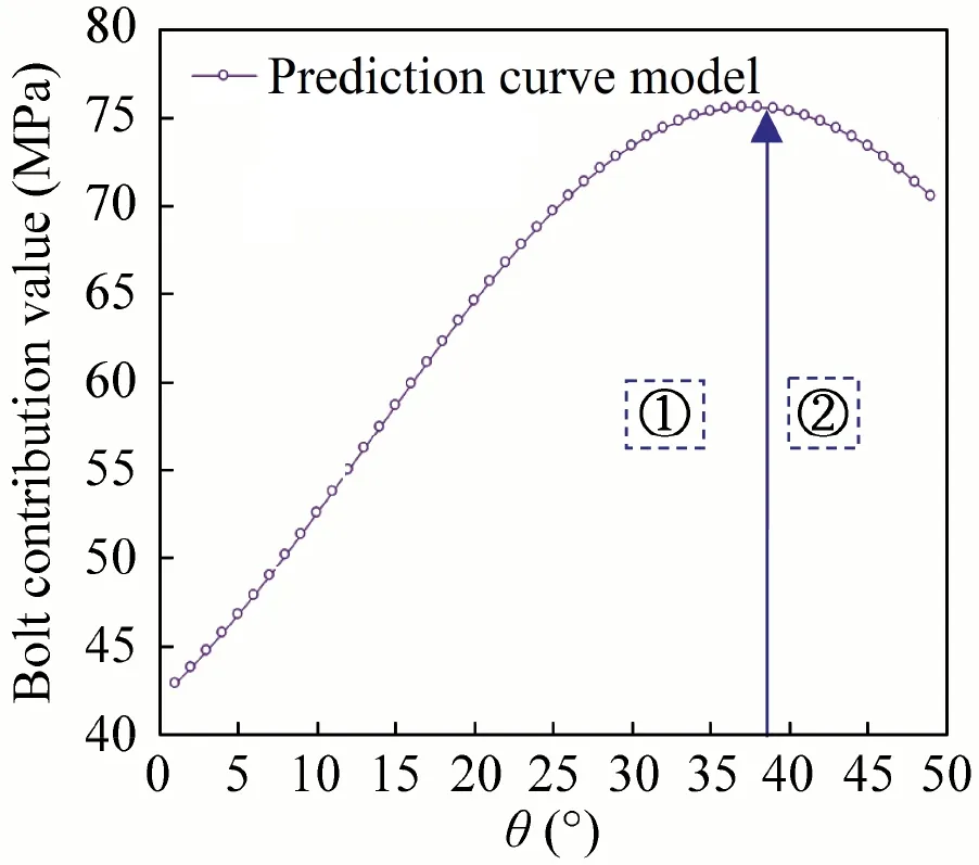
Fig.12.Relationship between the anchoring angle and the strength increment of the RC combined system contact plane (β=26°,σb=5 MPa).
The relationship between the increment of UCS (contribution value of bolt) and the anchoring angle with and without bolt is illustrated in Fig.13a.The anchoring effect is small when the anchoring angle is 15°(σb=0.05 MPa,σq=0.01 MPa).The anchoring angle of the bolt is in direct proportion to the increase of the UCS of the RC combined system when θ<38°.The larger anchoring angle is(i.e.the coal and rock inclination angle),the higher the UCS value will be.In contrast,the UCS decreases with the increase of anchoring angle when the inclination angle exceeds 38°.The scatter points of the test data are in good agreement with the prediction curve of the model.Additionally,Grasselli carried out shear tests on jointed rock mass with different anchoring angles(0–45°)and different bolt numbers [61].According to the bolt-reinforced joint shear test results with different inclination angles,it can be concluded that there is also an optimal anchoring angle (i.e.45°)in the shear test,which makes the contribution value of the bolt reach the maximum.The prediction of the model data can also well conform to the variation rule of the test results(Fig.13b),when the internal friction angle is 15°,bolt diameter D is 20 mm,and bolt number n is 2.

Fig.11.Relationship between the anchoring angle,the number of bolts,and the increment of the compressive strength of the cracked structural plane.
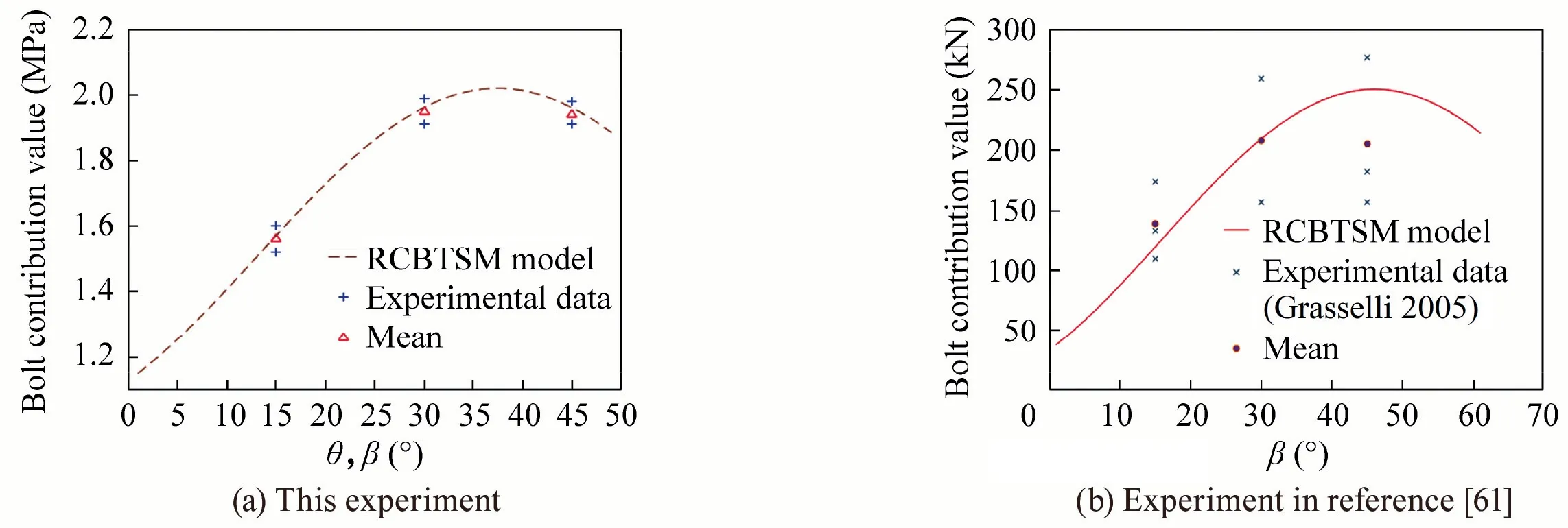
Fig.13.Comparison of results of the model and experiments.
6.Conclusions
In this study,the mechanical performance of the RC/RCB composite system was tested and analyzed.Combined with relevant mechanical theories and experimental results,the rock-coal-bolt tensile-shear mechanical (RCBTSM) model was deduced and verified.The following conclusions can be obtained.
(1) The anchoring reinforcement formed by bolting and coalrock changes the failure distribution mode and stress curve characteristics of the RCB composite system.It mainly limits the macro fracture and the release of elastic deformation energy near the RCB composite system’s peak value.The bolts unify the differences in the mechanical parameters of the composite rock.
(2) The dilatancy angle is critical to judging whether the bolt and RC composite systems are continuously damaged.The bolt diameter and the position of the RC composite system contact face also affect the change in the bolt resistance contribution.
(3) The relationship between the anchoring angle of the bolt and the UCS increment of the RC composite system shows a highly linear correlation when θ<38°.The larger the anchoring angle(i.e.the larger the coal-rock interface angle)is,the more significant increase of UCS will be.After the angle exceeds 38°,the UCS decreases with the increase of anchoring angle.
Most notably,the complex post-peak mechanical properties of the RCB composite system have a significant impact on the rock bolt.The post-peak fluctuation and the damaged area of the anchored specimen have been improved.Therefore,it should be considered in engineering practice to prevent the bolt from entering the ultimate tensile-shear state prematurely.
Acknowledgements
This study was financially supported by Beijing Outstanding Young Scientist Program(BJJWZYJH01201911413037),the projects supported by National Natural Science Foundation of China(Grants Nos.41877257,51622404,and 51974117),Shaanxi Coal Group Key Project (2018SMHKJ-A-J-03),and Yueqi outstanding scholar Award Program by CUMTB.The authors would also like to express appreciation to the reviewers and editor for their valuable comments and suggestions that helped improve the quality of this paper.
杂志排行
矿业科学技术学报的其它文章
- Identification of digital technologies and digitalisation trends in the mining industry
- Creep characteristics of coal and rock investigated by nanoindentation
- An experimental investigation of the fracturing behaviour of rock-like materials containing two V-shaped parallelogram flaws
- Comparative evaluation of different statistical tools for the prediction of uniaxial compressive strength of rocks
- A rapid and accurate direct measurement method of underground coal seam gas content based on dynamic diffusion theory
- Optimization of gob ventilation boreholes design in longwall mining
