Environmentally assisted cracking behavior of U-bend specimens of Mg-RE alloys in chloride containing basic solution
2020-12-18JakraphanNinlachartNikunjaShresthaKrishnanRaja
Jakraphan Ninlachart,Nikunja Shrestha,Krishnan S.Raja
a Department of Marine Engineering,Academic Branch,Royal Thai Naval Academy,Samut Prakan 10270,Thailand
b Chemical and Materials Engineering,University of Idaho,Moscow,ID 83844-1021,USA
Received 1 December 2019;received in revised form 15 March 2020;accepted 13 April 2020 Available online 3 June 2020
Abstract Environmentally assisted cracking(EAC)behavior of two Mg-rare earth(RE)alloys such as Mg-Zn-Gd-Nd-Zr(EV31A)and Mg-Y-Nd(WE43C)alloys was investigated by using U-bend specimens.Open circuit potentials(OCP)of the U-bend specimens were monitored during the EAC tests in 0.1 M NaOH solution with different chloride concentrations at room temperature.EV31A(as-received,and peak aged)and WE43C(peak aged)specimens failed by SCC in 80 ppm chloride containing 0.1 M NaOH solution at OCP.When the EAC initiation occurred,the OCP decreased continuously.Irregular fluctuation of the OCP were observed in the absence of EAC.The OCP versus time profil could be used for monitoring EAC failure of the Mg-RE alloy components in real life service.Applied potentials did not cause cracking of the EV31A alloy in 80 ppm Cl−containing 0.1 M NaOH.Accelerated cracking was observed on the WE43C alloy in peak-aged condition under the applied potentials in the transpassive region when compared to that of OCP condition.Overaging decreased the susceptibility to cracking.© 2020 Published by Elsevier B.V.on behalf of Chongqing University.This is an open access article under the CC BY-NC-ND license.(http://creativecommons.org/licenses/by-nc-nd/4.0/)Peer review under responsibility of Chongqing University
Keywords:Magnesium rare earth(Mg-RE)alloy;Stress corrosion cracking;Hydrogen assisted cracking;Localized corrosion.
1.Introduction
Mg-RE-Zr alloys such as EV31A(Mg-Zn-Gd-Nd-Zr alloy),and WE43C(Mg-Y-Nd alloy)retain high strength at elevated temperatures(∼300 °C)[1].Addition of rare earth elements such as Nd,Gd,and Y impart strengthening at high temperatures through solid solution strengthening and precipitation hardening due to formation of metastableβ′andβ1phases[2].Mg alloys are susceptible to environmentally assisted cracking(EAC)including stress corrosion cracking(SCC),and hydrogen assisted cracking(HAC)[3].The susceptibility of Mg alloys to SCC may depend on their alloying elements,for example,Zr-containing alloys are less susceptible than Zr-free alloys[4],and Mg alloys with the compositions containing rare-earth elements are reported to have improved SCC resistance[5].Wrought Mg alloys are more susceptible to SCC than cast Mg alloys[4].
Kannan et al.[5]studied SCC behavior of Mg-RE alloys such as ZE41,QE22 and EV31A(Elektron 21)and compared the results with that of AZ80 in distilled water,and 0.5 wt% NaCl solution under slow strain rate test(SSRT)conditions.The results showed that AZ80 was equally susceptible to SCC both in distilled water,and 0.5 wt% NaCl solution while,ZE41,QE22 and EV31A were more susceptible to SCC in 0.5 wt% NaCl than in distilled water.The fracture mode varied with the grain size of the materials.Finer grains in AZ80 showed transgranular cracking(TGSCC)mode,whereas,coarser grains in ZE41,QE22,and EV31A showed mixed TGSCC and intergranular cracking(IGSCC)modes[5].Padekar et al.[6-8]investigated SCC behavior of EV31A(Elektron 21)in different electrolytes such as:distilled water,0.01 M and 0.1 M NaCl saturated with Mg(OH)2solution,and compared the results with that of AZ91E by using SSRT,and constant load test(CLT).The SSRT results showed that both EV31A and AZ91E were susceptible to SCC in all three environments investigated.However,EV31A showed better SCC resistance than AZ91E.The fracture mode of AZ91E was TGSCC in all the test solutions,while EV31A revealed TGSCC in distilled water,and mixed IGSCC and TGSCC in chloride-containing solutions[7].The constant load test was carried out in 0.1 M NaCl saturated with Mg(OH)2solution[6,8].The results showed that 60%of the yield stress was sufficien to cause SCC in AZ91E,whereas no SCC failure was observed in EV31A even after 1008 h of testing at a stress level of more than 100% of the yield strength[8].
Raman and co-workers[9]studied SCC behavior of biodegradable and Al-free Mg alloys ZX50,WZ21,and WE43 in simulated body flui by using SSRT.They found out that WE43 failed in ductile mode in air because of mechanical overload whereas it showed mixed TGSCC and IGSCC in the simulated body fluid IGSCC was related to large precipitates at grain boundaries which caused electrochemical dissolution.They also applied cathodic potentials during SSRT,and compared the results with that obtained at OCP.The results showed not much difference in total strain-to-failure of WE43 between cathodic bias and OCP,the fracture mode was TGSCC,and the failure was associated with hydrogen assisted cracking[9].Recently,the effect of grain size on SCC of as extruded Mg-6.2Zn-0.8Zr alloy was reported under different bimodal grain size conditions[10].Fine grains showed IGSCC and coarse grains showed TGSCC.Li et al.[11]reported SCC behavior of EV31A in 0.1 M Na2SO4saturated with Mg(OH)2and the results were compared with that of pure Mg and WE43B.Threshold stress for SCC of Mg,EV31A,and WE43B was 0.3σys,0.6σys,and 0.8σys,respectively.The SCC velocity of Mg,EV31A,and WE43B was 7.2×10−8,5.6×10−9,and 1.5×10⁻⁹m/s,respectively at a stress rate of 7.3×10⁻⁴MPa/s.
The review of published reports indicated that most of the literature on SCC of Mg-RE alloys pertains to testing under SSRT.Since the samples are subjected to continuous straining during the SSRT,passive fil formed on the specimen surface may not be in a steady state and therefore it is diffi cult to investigate the role of stable passive fil on SCC as suggested in Ref.[6].Under constant load conditions,SCC was not observed on the Mg-RE alloys(EV31A)within a reasonable time scale conducive in laboratory[6,8].Typically,IGSCC of Mg alloys was attributed to the anodic dissolution of grain boundary region due to microgalvanic effect of grain boundary precipitates,and the transgranular cracking mode was associated with the hydrogen assisted cracking[12].Passivity is not generally observed in the Mg alloys exposed to neutral or low pH solutions even though this term is loosely used while describing the SCC behavior of Mg alloys[13].Therefore,the SCC mechanism associated with passive fil breakdown and anodic dissolution may not be applicable to the Mg alloys.Furthermore,the deformation behavior of Mg alloys having hcp lattice structure is different from that of alloys having bcc or fcc structures.In the hcp structure no f ve independent slip systems operate to satisfy the von Mises criterion for uniform deformation.Therefore,twinning or non-basal slip system needs to be activated[14].Twin systems consisting of{10-12}@<10-11>are activated during plastic deformation of Mg and Mg alloys.Large(100μm)grains show more susceptibility for twin assisted deformation than the small grains(3μm)[15].The Volta potential difference between twinned and untwinned region was reported to be about 200 mV which would provide a driving force for localized corrosion[16].Therefore,twin boundaries could act as preferential sites for stress corrosion crack propagation by anodic dissolution.Also,twin boundaries have been considered to provide preferential pathways for hydrogen diffusion[17].These observations indicate that environmental assisted cracking of Mg alloys could be associated with both anodic dissolution and hydrogen assisted cracking along twin boundaries.The SCC behavior of Mg and Mg alloys is different from that of alloys with a cubic lattice structure where stacking fault energy played a significan role.In general,stacking fault energies were high for an immune material with fcc structure and low for a susceptible material.Lowering stacking fault energy restricted cross slip,and promoted planar slip[18].Planar dislocation arrays in austenitic stainless steels promoted SCC while cellular dislocation structure mitigated SCC[19].Dislocation pileup played a crucial role as the crack followed dislocation pile up locations in ferrous alloys[20].The role of deformation characteristics on the surface fil breakdown and SCC behavior of Mg alloys is not fully documented in the available literature.An additional complication arises from the negative difference effect(NDE)observed in the Mg alloys.Since the hydrogen evolution rate increases with the anodic polarization the individual contribution of anodic dissolution,and hydrogen assisted mechanism on the environmental assisted cracking of Mg alloys cannot be clearly discerned.The major objective of this investigation was to understand the role of passive fil rupture on the SCC behavior of Mg-RE alloys by testing them in a high alkaline environment.
In this study,EAC of EV31A,and WE43C in different heat treated conditions was investigated using U-bend type samples in 0.1 M NaOH with different chloride concentrations.Using U-bend samples,threshold stress(σSCC)level for SCC cannot be determined but the susceptibility of different alloy compositions and heat treatment conditions can be compared.The fracture mode and crack initiation behavior can also be investigated using U-bend samples.This method is not only simple and cost-effective(as multiple samples can be tested at the same time without requiring loading fixtures)but also the most severe straining condition can be applied because large amounts of elastic and plastic strain are present[21].The alkaline test environment was selected based on our previous work on the localized corrosion susceptibility of EV31A and WE43C alloys in alkaline solution containing chlorides[22,23].In this pH condition,a‘protective'Mg(OH)2surface fil is formed on the Mg alloys.Therefore,the role of surface fil on the SCC behavior can be evaluated in this pH condition.Our earlier results showed that the threshold chloride required for passive fil breakdown in 0.1 M NaOH was 80 ppm for EV31A,and 200 ppm for WE43C.

Fig.1.U-bend dimensions of(a)EV31A,and(b)WE43C.
This work focuses on the role of protective surface layer on the EAC mechanism of Mg-RE alloys.The EAC occurred in combination of the fil rupture and anodic dissolution mechanism and hydrogen adsorption induced dislocation emission mechanism.Hydrogen alone(under cathodic polarization)could not initiate the EAC.However,hydrogen played a significan role in the crack propagation.
2.Experimental
2.1.Material and characterization
The materials used in this investigation were Mg-Zn-Gd-Nd-Zr alloy(EV31A)and Mg-Y-Nd alloy(Elektron 43 or WE43C)in wrought 16-mm-thick plate form(hereafter referred to as‘as-received'or‘AR').Both Mg alloys were donated by Magnesium Elektron N.A.Inc.The specimens were cut in transverse to the rolling direction with the dimensions as shown in Fig.1(a)and(b).They were machined close to the required thickness and ground to the fina thickness(1.0 mm)as the last step.The as-received(AR)EV31A strips were solution heat-treated at 525 °C for 8 h in nitrogen atmosphere and quenched in water at room temperature.This condition is referred to as solution-treated or ST.The solution treated EV31A strips were given two different aging treatments:(1)aging at 200 °C for 16 h,referred to as peak aging(PA),and 2)aging at 300 °C for 4 h which is referred to as overaging(OA).The as-received WE43C strips,also was solution heat-treated at 525 °C for 8 h in the nitrogen atmosphere and quenched in water at room temperature.The WE43C-ST coupons were aged to two different conditions:peak aging at 200°C for 168 h(PA),and overaging at 300°C for 2 h(OA).It should be noted that the two Mg-RE alloys had two different aging heat treatment parameters to achieve the PA and OA conditions.All samples were cooled in air after aging.The strips were ground with coarse SiC papers to obtain a fina thickness of 1 mm.The outer surface of the strips was metallographically polished down to 1500 grit finish cleaned with acetone,dried in air before bending,and cleaned with acetone and dried in air again after bending.The bending was carried out in two stages following the procedure outline in ASTM G 30[24]as shown in Fig.2(a)and(b)with a bend radius of 10 mm.Stainless steel bolts and nuts,were used to maintain the legs of the U-bend parallel to each other.Plastic sheaths and washers were used for insulating the stainless steel bolts and nuts from galvanic coupling with the sample.The outer surface of the U-bend sample has a constant tensile strain and inner surface is under compressive strain whose magnitude is given by the well-established relation:
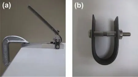
Fig.2.Two-stage bending configuration(a)frst-stage to form approximately U-shape,and(b)second-stage to form test stress.

where,ε=strain,t=thickness of sample,R=bend radius.
The U-shape specimens were inspected for presence of any cracks with 10X magnifying glass after bending prior to SCC testing,and then they were assembled in the electrochemical cell.The specimens designated as“unstressed”were cut in transverse to the rolling direction with the dimensions of 1.6 cm×2.5 cm×0.3 cm.Heat treatment and cleaning procedure were the same as that of the U-bend specimens.The unstressed specimens were ground with SiC papers down to 1500 grit for electrochemical measurement,and using 1-μm diamond suspension for microstructural observation.
2.2.Electrochemical tests and environments
The U-bend specimens of EV31A and WE43C in all heat treatment conditions were assembled in 400 ml beakers f lled with 250 ml of test solution and covered with lids.The electrolytes were 0.1 M NaOH(pH 13.5)with different chloride concentrations(80,100,and 200 ppm Cl−in the form of NaCl).Deionized(DI)water(resistivity 18.2×10⁶ohm-cm)obtained from a water purifie(MilliPore Model:Milli-QPF Plus)and reagent grade chemicals were used for preparing the test solutions.The open circuit potential(OCP)of U-bend specimen was measured by using a potentiostat(VersaSTAT MC,and VersaStudio software version 2.42.3 from Princeton Applied Research)for the firs 48 h of exposure.A spiraled Pt wire(0.5 mm diameter and∼700 mm long with a total exposed surface area of about 9.4 cm2)was the counter electrode,KCl-saturated Ag/AgCl(199 mV vs SHE)was the reference electrode,and the U-bend specimen(exposed total surface area∼10 cm2)was the working electrode.After 48 h,the potentiostatic connection was removed from the electrochemical cell,and the OCP was measure twice a day by using a multimeter(Fluke Model 26III)and a KCl-saturated Ag/AgCl reference electrode.The OCP measurements continued until the samples failed.SCC tests under anodic bias were carried out on the U-bend samples by applying constant potentials.SCC tests under cathodic bias were carried out by applying a cathodic current density of−10 mA/cm2.All tests were carried out at room temperature without controlling the dissolved oxygen in the electrolyte.For comparison,U-bend specimens of EV31A-as received,and WE43C-peak aged were tested in 0.1 M NaOH solution(without any chloride addition)at open circuit condition for 21 days.
Cyclic polarization was carried out on both U-bend and unstressed specimens by scanning the potential from 0 V vs OCP to 2.5 V vs reference electrode at scan rate of 1 mV/s.The scan direction was reversed when the potential reached 2.5 VAg/AgClor the transpassive current density reached 1 mA/cm2(whichever occurred frst).All the tests were duplicated or triplicated in some cases in order to check reproducibility.The variation in the results was within±20%.The best representing reproducible results are discussed in this report.
2.3.Microstructure and fractography
The polished specimens were etched with glycol etchant containing 10 ml HNO3,24 ml DI water,75 ml ethylene glycol to reveal the microstructure.The SCC tested U-bend specimens were rinsed with DI water,and cleaned with acetone under ultrasonication.The optical microscopy was conducted by using an OLYMPUS PMG3 optical microscope,and the scanning electron microscopy(SEM)was conducted by using a FE-SEM(LEO SUPRA 35VP)with an energy-dispersive X-ray spectroscopy(EDS)detector.The grain sizes of the specimens were determined manually by using a linear intercept method as per the ASTM standard E112-13.Gracing angle X-ray diffraction patterns were obtained using a Rigaku Smartlab 3 kW with Cu kαX-ray tube operated to 40 kV and 44 mA,where the incident angle of the X-rays was 0.5° with respect to the sample surface.
3.Results and discussion
3.1.Microstructure
Fig.3(a)-(e)shows optical microstructures of EV31A and WE43C in unstressed conditions.Fig.3(a)shows the microstructure of EV31A in as-received(AR)condition with fin grains and texture across the sample.The grain size varied between 10 and 14μm.The secondary phases were identifie as Mg12Nd,Mg3RE,and Mg41Nd5[22].The Vickers hardness number(VHN)of EV31A-AR specimen was∼66 kgf/mm2.The grain size of EV31A in the peak-aged(PA)condition was larger than that of AR condition due to the high temperature solution treatment that preceded the aging treatment and was in the range of 25 to 63μm with an average of 45μm as shown in Fig.3(b).The peak aged microstructure still showed some texture,but was less significan than that was in the AR condition.The secondary phase found in the peak aged condition wasβ′′which had nanoscale size,and could not be detected by the optical microscope[22].Presence of this phase resulted in a peak hardness of 84 VHN in spite of having a larger grain size than that of AR condition.Microstructure of EV31A in overaged condition is shown in Fig.3(c).Grain size of OA samples varied widely between 25 and 140μm,with an average of 76μm.The dark-etched grains were the result of a high volume fraction of cellular-typeβphase(Mg3RE)[22].The hardness of EV31A-OA was about 68 VHN.Fig.3(d)illustrates microstructure of as-received WE43C specimen.A fin grain size between 9 and 16μm and texture were observed in this condition.The hardness was about 96 VHN.The XRD analysis revealed presence of secondary phases such as Mg12Nd,Mg24Y5,Mg41Nd5,and Mg3Gd in the as-received WE43C[23].Microstructure of WE43C in peak-aged condition(WE43C-PA)is shown in Fig.3(e).The grain size of the peak aged sample was significantl larger(average∼92μm)than that of as-received condition.The grain growth occurred during the solution treatment and the textured feature completely disappeared in WE43C-PA,in contrast to the microstructure of EV31A-PA.The hardness of WE43C-PA was about 100 VHN.
3.2.SCC at open circuit potential(OCP)
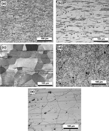
Fig.3.Optical microstructure of EV31A and WE43C in unstressed conditions;(a)as-received of EV31A,(b)peak-aged of EV31A,(c)overaged of EV31A,(d)as-received of WE43C,and(e)peak-aged of WE43C.
Fig.4(a)and(b)shows open circuit potential(OCP)plots of EV31A and WE43C specimens in different heat treated conditions in 0.1 M NaOH with 80 ppm chloride concentration for the frst 48 h,and after 48 h,respectively.Table 1 summarizes the initial,the most positive,fina OCPs derived from the plots in Fig.4(a)and(b),time at which a crack observed frst,and time to failure(that cracks propagated throughout the width of the specimen and total failure of sample).It should be noted here that the crack propagation occurs in two dimensions-across the thickness and along the width of the U-bend specimens(possibly as a thumbnail crack).Dimension of the crack along the width is referred to as crack length with an assumption that the crack is a through thickness crack.The OCP transient of unstressed specimen is considered firs as a reference for further comparison with the Ubend specimens.The OCP of the unstressed peak-aged specimen increased significantl from−1.64 VAg/AgClto−1.16 VAg/AgClfor the firs 25 min then decreased steeply to−1.52 VAg/AgClfor the next 7 min(Fig.4(a)).This increase-decrease fluctuatio occurred again,then the OCP increased sharply to−0.86 VAg/AgClat hour 2.After the significan fluctuations the OCP gradually increased to−0.77 VAg/AgClat hour 26.From 26 to 48 h,the OCP fluctuate in the range of−0.79 and−0.94 VAg/AgCl.Marquis and co-worker[25]observed a similar behavior in the WE43 Mg alloy immersed in 3.5 wt%NaCl.They attributed the increase in the OCP to the formation of a passive film and the decrease in the OCP to the passive fil break-down.The subsequent increase of OCPwas associated with the repair of the ruptured passive film After recovery,the fil became thicker[25].Similar OCP fluctuation were reported in alkaline solutions without chloride addition for the Mg-Al alloys in the unstressed condition[26].Potential fluctuation were observed in the unstressed Mg-RE coupons also in 0.1 M NaOH without chloride addition[27].Addition of 80 ppm chloride to 0.1 M NaOH did not affect the magnitude of the potential fluctuations
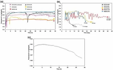
Fig.4.Open circuit potential(OCP)plots of the specimens in 0.1 M NaOH with 80 ppm chloride concentration;(a)the firs 48 h,(b)after 48 h,and(c)OCP of EV31A as-received after cracks showed.AR as-received,PA peak-aged,OA overaged.

Table 1Summary of the initial,the most positive,f nal OCPs from the plots in Fig.4(a)and(b),and time to crack completely.
OCP of the EV31A-AR U-bend specimen increased significantly from−1.39 VAg/AgClto−0.71 VAg/AgCl,and two small bumps were present at the frst 5 h of exposure.After that,the OCP was almost constant at−0.62 VAg/AgCluntil 20 h.The OCP decreased sharply after 20 h,to−1.30 VAg/AgCl,and increased steeply again to−0.88 VAg/AgClwithin 3 h.Even though the OCP slightly increased after this point,it showed minor fluctuation until 48 h.This fluctuatio could have occurred because of initiation of pits on the sample's arms(unstressed portions of the U-shape)just below the solution level.The OCP of EV31A in peak-aged condition increased significantly from−1.34 to−0.6 VAg/AgCland was constant for 9 h.The OCP gradually decreased to−0.77 VAg/AgClwhen it reached 48 h.The OCP transient of EV31A-OA indicated that overaged specimen spent more time to form a thicker passive layer compared to the as-received sample as the OCP remained more negative for an extended period of time.As seen from Fig.4(a),the OCP of the EV31A-OA increased from−1.53 to−1.05 VAg/AgCl,during the firs 3 h and then decreased steeply to−1.43 VAg/AgCl.When the passive fil repaired,the OCP moved upward to−0.92 VAg/AgCl,and fluc tuated.The fluctuation could again be attributed to initiation of pitting on the arms(unstressed part)of the U-bend sample that were just below the solution level.Initiation of pits was observed at the unstressed arms;whereas,no pits were observed on the bent(strained)region.The OA samples showed the most active OCP values among the specimens tested.Interestingly,the specimens EV31A-PA,WE43C AR,and WE43C-PA showed almost similar OCP profil without significan fluctuations The increase in OCP of the WE43C as-received sample at the initial stage is quite low compared to the OCP of both EV31A and WE43C in the peak-aged conditions.The OCP of WE43C-AR specimen moved in positive direction from−1.43 VAg/AgClto−1.20 VAg/AgCl,then slightly increased to−1.07 VAg/AgClat hour 20.From this point to hour 48,the OCP profil showed fluctuation due to pitting corrosion at the arms of the sample at the solution/air interface.For the peak-aged WE43C,the OCP increased significantl from−1.53 VAg/AgClto−0.79 VAg/AgClfor the firs 3 h of exposure.Then the OCP gradually increased to−0.61 VAg/AgClfor the next 11 h,and was almost constant until hour 48.
TheV−tprofile of the U-bend specimens could be related to their microstructural conditions,deformation characteristics(twins versus basal and pyramidal dislocations),nature of surface film hydrogen evolution rate on the surface(due to NDE),and hydrogen diffusion in the material.The potential fluctuation were relative lower in the strained condition than that observed on the unstrained specimen.This observation indicates that a more stable surface layer was formed on the strained surface than that of the unstrained condition.Since the Pilling-Bedworth ratio of Mg(OH)2is 1.77,a compressive residual stress could be expected on the surface.Tensile stresses present on the outer surface of U-bend specimens would compensate for the compressive growth stresses of the Mg(OH)2,which in turn,lead to better stability of the surface layer and less number of fluctuations As discussed in an earlier section,twins will be activated during plastic deformation of large grain structures specimens such as EV31A-PA,EV31A-OA,and WE43C-PA.However,twin formation will be difficul in smaller grains such as-received conditions of EV31A and WE43C.Addition of rare earth elements such as Nd,Gd,and Y changes stacking fault energy of Mg,and enhances solute-drag of grain boundaries and dislocation pinning effect[28].The reduction in the energy of basalI1stacking fault(sessile ABABACAC stacking)helped nucleate dislocations on pyramid planes<c+a>.Typically the rare earth elements(RE)segregate at dislocations and grain boundaries[28].
The increase in the OCP could be hypothetically explained based on the mixed potential theory by considering the following factors:(a)thickening of the surface layer that leads to a lower corrosion current of the anodic reaction;(b)increase in the Tafel slope and/or decrease in exchange current density for with time for the anodic reaction,but the cathodic reaction parameters do not change with time;(c)increase in the cathodic reaction kinetics with time(increase in exchange current density,and shallower Tafel slope)but the anodic reaction kinetics remain the same,and(d)combinations of the afore mentioned factors.The decrease in the OCP follows the similar line of reasoning with an opposite trend.In addition to the mixed potential theory,the deformation dynamics such as emergence of slip planes/dislocations/twins at the surface cutting the surface layer and exposing bare metal would also influenc the OCP.Furthermore,a significan magnitude of stress gradient exists across the thickness of the U-bend specimens which could be an additional driving force for diffusion of species across the meta/film and film/electrolyt interfaces.The diffusion flu could affect the OCP values as a function of time.These are just speculations.No experimental data on the exchange current densities(i0),and Tafel slopes(βaandβc)as a function of time or available to support the above speculations.In a latter section,the values ofi0andβcfor hydrogen evolution are given(Table 3)for a freshly polished and surface layered covered surfaces,but not as a function of time.In order to know the exact reason behind increase in the OCP or fluctuation in the OCP more analyses are required.It was observed that the exchange current density increased with fil coverage.The fluctuation of potential were significant in the AR specimens which could be related to smaller grain size,and microgalvanic effect due to secondary phases observed along the grain boundaries.The overaged EV31A also showed significan potential fluctuation and more active potentials which could be associated with the large volume fraction ofβ-phase that could promote galvanic coupling with theα-matrix.
Long-term OCP monitoring after the initial 48-h recording was carried out using a digital multimeter.Fig.4(b)shows the OCP vs time plots recorded at every 12 h during the SCC tests of U-bend samples.The OCP of EV31A as-received specimen fluctuate between−1.30 VAg/AgCland−0.7 VAg/AgClfor 5 days.Then the OCP decreased significantl for the next 3 days before the OCP was almost stabilized at−1.6 VAg/AgCl.At the constant potential region,many small cracks were observed with an average crack length of 3.5 mm(data not shown here).After 12 h,the average crack length became 6.1 mm,with an estimated average crack growth rate of∼6×10⁻⁸m/s.This estimation of crack velocity is only for comparison of results of this study and no deterministic value could be derived out of this observed result.This crack velocity was similar in the order of magnitude(2.2×10⁻⁸m/s)reported for the case of galvanically induced crack growth by Atrens'group[29].At this stage,the OCP was recorded continuously using a potentiostat.The plot of OCP is shown in Fig.4(c).Saw-teeth like potential fluc tuations were observed at the crack propagation stage.Each fluctuatio wave could possibly be associated with an increment of a crack.The width of each fluctuatio peak varied between 10 and 15 min,and the height of the peak varied between 0.9 and 1.5 mV.The width and amplitude of the potential fluctuation were consistent which implied that each fluctuatio could correspond to a constant magnitude of crack increment.The potential decreased continuously during the fi nal crack growth stage.The EV31A as-received sample completely cracked in 13 days of exposure to the 80 ppm chloride containing 0.1 M NaOH solution as summarized in Table 1.A second specimen cracked in 14 days.The OCP transient profil of EV31A peak-aged specimen was almost similar to that of the as-received specimen.The fluctuatio of OCP for the frst 4 days was between−0.95 and−0.68 VAg/AgCl.The OCP moved downward(more negative direction)from−0.68 VAg/AgClto−1.60 VAg/AgClwithin 5 days of exposure,and then the OCP was constant and cracks were observed.Before the specimen completely cracked,the OCP decreased from−1.61 to−1.74 VAg/AgCl.The peak-aged specimen of EV31A cracked in 19 days of exposure,while the second specimen cracked in 16 days.The EV31A overaged specimen showed extreme fluctuatio of OCP(−1.33 to−0.58 VAg/AgCl)during the frst 4 days,and became almost constant at−0.6 VAg/AgClfor the next 11 days.The OCP then moved in the negative direction to−1.42 VAg/AgCland stayed constant until cracks propagated throughout the width of the specimen and complete fracture occurred at day 38.For the WE43C as-received specimen,the OCP showed widely varying fluctuation after 48 h of exposure.The OCPs after 48 h fluctuate in the range of−1.32 and−0.66 VAg/AgCl.The fluctuation could be attributed to the corrosion on the arms of the specimen above the aqueous solution whereas the U-bend area immersed in the solution did not show any evidence of pitting corrosion or cracks due to SCC.The specimen did not show stress corrosion crack initiation for more than 43 days and the experiment was terminated after 43 days of exposure.The peakaged specimen of WE43C showed a V-t profil more or less similar to that of EV31A specimen in the overaged condition but with more number of fluctuation in the range of−0.86 and−0.59 VAg/AgCl.The WE43C in peak-aged condition cracked into 2 pieces in 23 days.The second sample failed in 25.5 days.The crack growth rate of the two WE43C peak-aged specimens approximated 5.56×10⁻⁷m/s(∼8 h from crack initiation to completely crack).
In terms of crack initiation and crack propagation,it could be seen from Table 1 that EV31A in overaged condition had the longest time for crack initiation and crack propagation which were 26 and 38 days,respectively.Even though the peak-aged specimens of both EV31A and WE43C had longer time for crack initiation than EV31A as-received specimen,crack propagation rates were much faster than that of EV31A as-received condition.Crack growth rate depends on heat treatment conditions which are related to mechanical properties.Higher the hardness,the faster was the crack growth rate.
Fig.5(a)and(b)shows OCP plots of the EV31A specimens in as-received condition in 0.1 M NaOH with different chloride concentrations for the firs 48 h,and after 48 h,respectively.In 100 ppm Cl−solution,two small fluctua tions due to formation-breakdown-repair of passive fil were present on the plot with the−1.49 VAg/AgClof initial OCP.At the third time of repassivation,the OCP was constant for around 1.5 h,increased again to−0.48 VAg/AgCl,and was almost constant at that potential.The specimen immersed in 200 ppm Cl−solution passivated continuously as the potential increased from−1.51 VAg/AgClto−0.81 VAg/AgClwithin 3 h,and the OCP fluctuate for approximately 2.5 h.The OCP then plunged to−1.39 VAg/AgCl,and moved upward again to−0.72 VAg/AgCl.After that potential recovery,the OCP fluctuate in a narrow range and gradually decreased.After 40 h,the fluctuatio of OCP was at a higher amplitude than that observed in the earlier period.At the end of 48 h exposure,localized corrosion at the solution/air interface was significan at the arms of the specimen.After 48 h of the continuous recording by a potentiostat,the OCP was measured using a multimeter at every 12 h in 80,100,200 ppm Cl−electrolyte and the results are shown in Fig.5(b).The OCP of the sample in the 100 ppm Cl−solution fluctuate for the whole period of the experiment.Even though the OCP of the sample in the 200 ppm Cl−solution did not signifi cantly fluctuat for the whole period of the experiment as in the 100 ppm Cl−,localized corrosion was observed on the arms of the specimen just below and above the solution level.The localized corrosion observed at the liquid-vapor interface indicated severity of this environment as compared to that of bulk liquid.Similar observations were reported for 316 L stainless steel and nickel base alloy 825 in 1000 ppm Cl−solution[30].Interestingly,the as-received of EV31A specimens exposed to 100 and 200 ppm Cl−solutions did not show any cracks at the bent(strained)regions of the U-bend sample.
Fig.5(c)and(d)shows OCP plots of the WE43C specimens in as-received condition in 0.1 M NaOH with different chloride concentrations for the firs 48 h,and after 48 h,respectively.As seen from Fig.5(c),the OCP of the WE43CAR in 100 ppm Cl−showed potential fluctuation predominantly due to formation-breakdown-repair of passive fil and not by localized corrosion.Three and a half loops of fluctua tions could be observed during the firs 48 h.When chloride concentration was increased to 200 ppm,the fluctuatio of OCP due to localized corrosion could be observed after 5 h of exposure while the fluctuatio for the frst 5 h could be attributed to formation-breakdown-repair of passive film After 48 h,the OCP fluctuation of the specimens in 100 and 200 ppm Cl−showed featureless pattern.It was observed that the increase in chloride concentration to 100 or 200 ppm did not affect the OCP of the U-bend specimens as compared to that of 80 ppm chloride solution.WE43C-AR in 100 and 200 ppm Cl−solutions showed similar resistance to SCC as that in 80 ppm Cl−as discussed early.The little or no influ ence of chloride ions between 80 and 200 ppm concentration on the OCP and SCC behavior could be explained based on the surface reactivity of magnesium alloy surface.The surface reactivity could be influence by the kosmotropic/chaotropic nature of the ions(Mg2+and Cl−)which is based on the ability to highly(kosmo)or poorly(chao)structure the water molecules around the ions[31].The Mg2+ion,because of its high surface charge density,will bind the water molecules more strongly than between H2O-OH2and considered kosmotrope.On the other hand,Cl−is a chaotrope because of its large size and low surface charge density.Kosmotropes are attracted to hydrophilic surfaces and repelled by hydrophobic surfaces while the chaotropes are attracted to hydrophobic surfaces[32].Furthermore,by applying the‘matching affinit concept'[33]it can be noted that oppositely charged kosmotropic Mg2+and chaotropic Cl−may not attract each other.On the other hand,kosmotropic OH-will combine with Mg2+to form Mg(OH)2,a reaction referred to as‘salting out'[34].Therefore,presence of chloride in low concentrations(<500 ppm at pH:13)may not significantl affect the surface layer containing Mg2+ions.
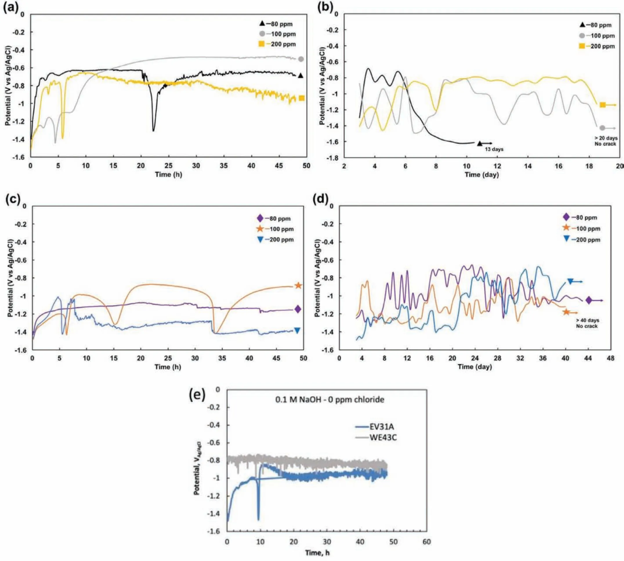
Fig.5.OCP plots of the specimens in as-received condition in 0.1 M NaOH with different chloride concentrations;(a)EV31A at the frst 48 h,(b)EV31A after 48 h,(c)WE43C at the frst 48 h,and(d)WE43C after 48 h,(e)0 ppm chloride EV31A and WE43C in as-received(AR)condition.
For comparison,SCC tests were carried out on EV31A(as-received)and WE43C(peak aged)specimens in 0.1 M NaOH solution(without chloride addition)under open circuit potential conditions for 21 days.The OCP of the specimens were monitored for the frst 48 h continuously and the results are shown in Fig.5(e).After initial potential excursions,the OCP values of both alloys almost stabilized at about−0.85 VAg/AgClafter 48 h.At the end of 21 days of exposure both the alloys showed almost similar potentials in the range of−0.82-0.84 VAg/AgCl.No cracking was observed on these specimens.The tests were interrupted after 21 days of exposure and specimens were observed under the SEM.
From the OCP profile it could be noticed that the OCP of the specimens,which failed by EAC,decreased gradually when cracks initiated and propagated.On the other hand,the OCP of the specimens which were susceptible only to localized corrosion but not to EAC showed a fluctuatin behavior without the monotonously decreasing trend.This observation could be applied to in-service monitoring of components.
3.3.Microscopy of specimens failed at OCP
Fig.6(a)and(b)shows optical micrographs of EV31A in overaged condition and WE43C peak-aged condition that failed at OCP,respectively.From Fig.6(a),it could be seen that cracks initiated at pits.It is not clear from the micrograph that if cracks propagated along grain boundaries or not.However,cracks on the area around localized corrosion were observed as intergranular.Cracks also initiated at the localized corrosion and propagated along grain boundaries in WE43C peak-aged specimen(Fig.6(b)).Our earlier work on the localized corrosion of EV31A[22]and WE43C[23]in different heat treatment conditions exposed to 0.1 M NaOH+500 ppm Cl−showed that pit initiation occurred within spherical secondary phase particles that were enriched in Zr.The localized corrosion observed on the U-bend specimens could also be attributed to the preferential dissolution of secondary particles.The intergranular cracking observed on the samples indicated that a possible SCC mechanism could be due to anodic dissolution of regions adjacent to the secondary phases[3].
Fig.6(c)and(e)shows the surface morphology of the unstressed region of EV31A(as received)specimen exposed to 0.1 M NaOH+80 ppm Cl−solution at open circuit condition for 1,5 and 10 days,respectively.The surface layer consisted of a fla y morphology consisting of leaf like Mg(OH)2platelets re-precipitated on the surface.There was no significant change in the surface morphology with the increase in the exposure time.On the other hand,the morphology of surface layer of the stressed region looked different from that of unstressed region,as seen in Fig 6(f)and(g).The stressed region showed a more compact surface layer consisting of disc shaped and acicular hydroxide/oxyhydroxide phases.The results of energy dispersive X-ray analyses spectroscopy(EDS)showed predominantly Mg and O peaks and the intensities of Nd and Gd were not significant The EDS results could not differentiate the composition of disc and acicular morphologies.Therefore,the EDS results are not shown here.Fig.6(f)and(g)shows the morphologies of stressed EV31A-AR specimens after 5 and 10 days of exposure in 80 ppm chloride solution of pH:13.5,respectively.The number density of acicular morphology in the surface layer increased with the exposure time.
Fig.6(h)and(i)shows the morphologies of the stressed regions of EV31A-AR and WE43C-PA specimens exposed to 0.1 M NaOH(without chloride addition)solution at OCP for 21 days,respectively.The surface layer formed in the 0.1 M NaOH solution without chloride addition was more compact than that observed in the 80 ppm chloride containing environment.No cracks were detected on the specimens after 21 days of exposure to 0.1 M NaOH solution.Therefore,the resistance to SCC in 0.1 M NaOH solution could be attributed to a more compact surface layer formed on the Mg-RE alloys.
Fig.7(a)-(g)shows features of the fractured surface of EV31A in as-received condition.Fig.7(a)shows the fractured surface at a low magnificatio where four different morphologies are seen in each segment with dimensions around 145,525,55,and 100μm across the thickness of the specimen.Fig.7(b)shows the magnifie view of outer fibe region(top 145μm thick).Secondary cracks are seen on the surface that was covered with a layer of corrosion product.The second region showed transgranular crack growth due to SCC with the localized secondary cracks as shown in Fig.7(c).The dimension of this region was around 525μm in the thickness direction.The third region was predominantly ductile with dimples and decohesion of secondary particles(Fig.7(d)).This region showed crack growth mainly by mechanical stress because around 3/4 of the cross-sectional area was already affected by SCC.This part was around 55μm thick.The mechanical fracture in the third part could lead to featureless smooth fracture surface which was the characteristic of the last part as shown in Fig.7(e).Plastic deformation was also observed on the smooth surface.This area was around 100μm thick.Fig.7(f)shows planar view of the outer surface of the Ubend sample that reveals mixed mode(primary intergranular cracks along with transgranular secondary cracks)cracking morphology.The outer surface was covered with Mg(OH)2fil as seen in Fig.7(g)at high magnification and secondary cracks due to SCC could be seen.The fractured surface was covered with the corrosion products that obliterated some of the features described.The initial efforts taken to remove the corrosion products by ultrasonication or selective chemical cleaning by boiling chromic acid solution(200 g/l)[35]were not useful for obtaining an unaltered f lm-free surface.Therefore,all the fractographic results pertain to surfaces covered with the corrosion products.
Fig.8(a)-(d)shows fracture features of the EV31A in peak-aged condition.The fracture showed both transgranular and intergranular mode,and secondary cracks were also observed as seen in Fig.8(a).Attack on specifi crystallographic planes that resembled transgranular morphology could be seen in Fig.8(b)(marked by arrow).Fig.8(c)and(d)shows top view of the outer surface subjected to tensile strain.The fracture morphology of EV31A-PA was similar to that of the EV31A as-received specimen.From the fracture morphology it is difficul to distinguish between the two possible SCC mechanisms such as fil rupture-dissolution or hydrogen assisted cracking.Cracks observed at specifi crystallographic planes(Fig.8(b))indicated possible hydrogen adsorption on certain planes that decreased the surface energy[36].
Fig.9(a)and(b)shows crack propagation on the outer(tensile)surface of the EV31A overaged U-bend sample.The fla e morphology of Mg(OH)2formed on the surface of the overaged(Fig.9(a))specimen appeared to be less dense than that observed on the as-received specimen.However,the overall thickness of the surface layer was significantl higher than that formed on the other heat treated conditions.The thick surface layer formed on the overaged specimen could be attributed to the longer incubation time required for crack initiation than that required for the as-received specimens.The firs crack of the as-received specimen was observed on day 9 with crack length of 3.5 mm,while for the overaged specimen a 2 mm long of crack was observed on day 26.Fig.9(b)shows significan dissolution of the fracture surface and deposition of corrosion products.The time taken for crack growth was also significantl long(∼12 days)during which time the cracked surfaces were exposed to the test solution that lead to the corrosion products to re-precipitate.It was noticed that even though crack propagated throughout the width of the U-bend specimen,the specimen did not separate into two pieces.Based on the nature of fina fracture and surface layer covered,‘fil rupture and dissolution'could be the predominant mechanism in the overaged condition.However,the role of hydrogen could not be precluded.

Fig.6.Microstructures of the specimen surface at different conditions:(a)optical microstructure of EV31A overaged,(b)optical microstructure of WE43C peak aged,(c)-(e)are EV31A coupons in the as received(AR)and unstressed conditions exposed to 0.1 M NaOH+80 ppm Cl−at OCP for 1 day(c),5 days(d),and 10 days(e),respectively.(f)and(g)are U-bend(stressed region)specimen surfaces of EV31A AR exposed to 0.1 M NaOH+80 ppm Cl−at OCP for 5 days(f),and 10 days(g),respectively.(h)and(i):surface morphology of stressed regions exposed to 0.1 M NaOH solution at OCP for 21 days:(h)EV31A as-received,and(i)WE43C peak aged.
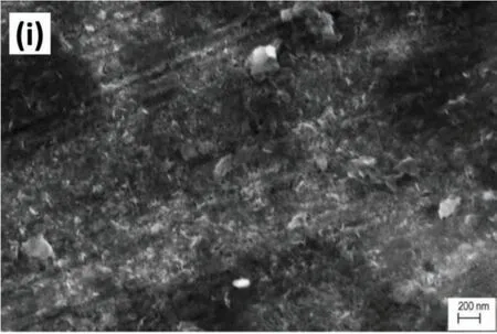
Fig.6.Continued
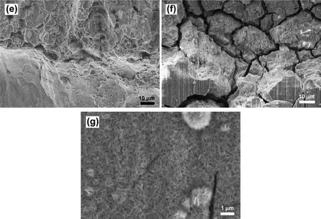
Fig.7.Fracture feature of EV31A in as-received condition;(a)cross sectional view showed 4 different fracture feature,(b)top section of(a),(c)second section of(a),(d)third section of(a),(e)bottom section of(a),(f)top view of tension side surface,and(g)passive f lm on the surface in(f).Noted that the length of each section in(a)was not the actual length,but it could be close to the actual length.The measurement gives an idea of the proportion of each fracture feature.
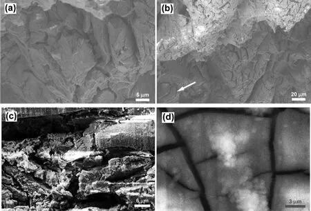
Fig.8.Fracture feature of EV31A in peak-aged condition;(a)transgranular and intergranular mode,and secondary cracks,(b)specifi crystallographic planes attack(marked by arrow),(c)top view of tension side surface,and(d)passive fil on the surface in(c).
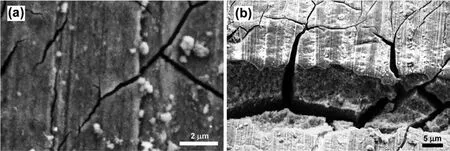
Fig.9.Crack propagation on top of the tension side surface of the EV31A overaged sample;(a)passive fil on crack surface,and(b)crack surface at low magnification
Fig.10(a)-(e)shows fractographs of the WE43C in peakaged condition.The cross-sectional fracture surface had two different fracture modes as seen in Fig.10(a).The upper section which was the tension side of the U-bend showed predominantly intergranular cracking with preferential attack on specifi crystallographic planes as seen in Fig.10(b).Some of the fracture planes appeared featureless,possibly indicating{0001}basal planes as cleavage planes where cracks propagated.Adjacent to those cleavage planes,fin parallel crystallographic planes running almost perpendicular to the basal planes could be observed as seen in Fig.10(b).These planes could be{10-1X}flute planes similar to that reported by Lynch and Trevena[37].The deposition of corrosion product could be observed on the fractured surface beneath the outer fibe.Minor cracks were observed running perpendicular to the primary crack growth direction as shown in Fig.10(c).Fig.10(d)shows predominantly transgranular mode at the region closer to the original neutral axis of the U-bend specimen,and smooth fracture surface with local plastic deformation was observed at the fina fracture surface where mechanical overload played a significan role.Fig.10(e)shows the crack initiation sites on the top surface of the outer fibe of the U-bend specimen.The crack initiation occurred at the intersection of pit and dislocations emerging from slip steps indicated by an arrow.Overall,SCC of the peak aged WE43C specimen at open circuit potential in alkaline chloride solution could have occurred in two stages viz.,stage 1:crack initiation which was controlled by the fil rupture and dissolution at the slip steps;and stage 2:crack propagation which occurred by reduction in cohesive strength of crystallographic planes by possible hydrogen adsorption.The effect of hydrogen on the EAC behavior will be discussed in a latter section.
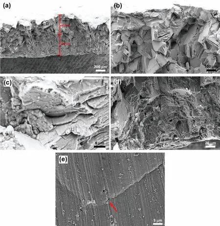
Fig.10.Fractures of WE43C in peak-aged condition;(a)two different fracture features,(b)upper section,(c)shallow level under tension surface,(d)lower section,and(e)crack propagation at the edge of slip step region.Noted that the length of each section in(a)was not the actual length,but it could be close to the actual length.The measurement gives an idea of the proportion of each fracture feature.
3.4.Cyclic polarization
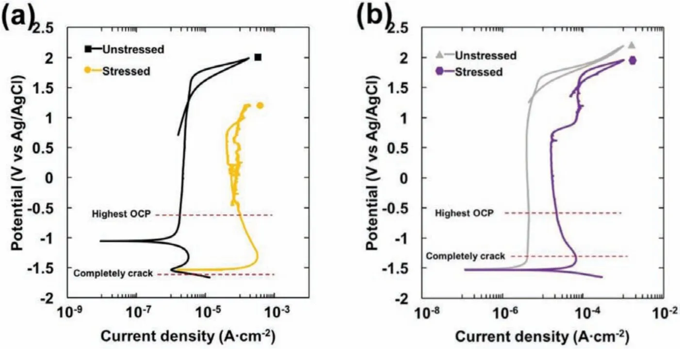
Fig.11.Cyclic polarization plots of the specimens with and without applied stress in 80 ppm Cl−+0.1 M NaOH solution;(a)EV31A as-received,and(b)WE43C peak-aged.

Table 2Cyclic polarization results from Fig.11(a)and(b).
In order to understand the relation between the stability of passive layer and the SCC susceptibility,cyclic polarization was carried out on the U-bend specimens and the results were compared with the polarization behavior of the unstressed coupons.Fig.11(a)and(b)shows cyclic polarization plots of EV31A as-received and WE43C peak-aged specimens with and without applied stress in 80 ppm Cl−+0.1 M NaOH solution.Table 2 summarizes the cyclic polarization results from Fig.11(a)and(b).The transpassivity of unstressed specimens was observed at>1.6 VAg/AgCl.If the transpassive condition was associated with just oxygen evolution reaction,no hysteresis could be expected.The hysteresis during the reverse scan and a cross-over potential indicated modificatio of the surface layer possibly by localized corrosion.The cross-over potential is referred to as pitting protection potential.From Fig.11(a),it can be seen that transpassive potential and pitting protection potential of the unstressed EV31A-AR were higher than that of the stressed specimen.The passive current density of the unstressed specimen was two decades lower than the stressed specimen.The polarization results indicated that the passive fil of the unstressed specimen was more protective and stable than the passive fil of stressed specimen.However,the morphologies of the surface layer of unstressed and stressed regions at OCP as presented in Fig.6 were not in supportive of the cyclic polarization results.The results obtained in the OCP conditions cannot be correlated with that of external bias conditions.It could be observed from Figs.4(a)and 11(a)that after passive fil broke down the specimen tried to repassivate,but the f lm was not able to recover which lead to initiation of pits.When the OCPs of EV31A as-received specimen from Fig.4(a)and(b)were superimposed on Fig.11(a),the highest OCP value recorded was in the passive range just negative to the pitting protection potential of the U-bend specimen;whereas the potential recorded during the crack growth period was in the cathodic region of the cyclic polarization plots.The transpassive potential and pitting protection potential of WE43C peak-aged specimens with and without applied stress were similar to each other,but the unstressed specimen showed lower passive current density.The passivation behavior from cyclic polarization plot correlated with the plot of OCP in Fig.4(a).When the OCPs from Fig.4(a)and(b)were superimposed on Fig.11(b),they were at the anodic region,while the potential recorded during the crack growth stage coincided with the Flade potential of the stressed sample.
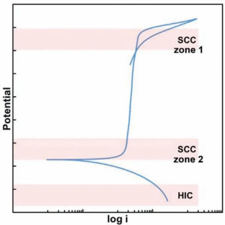
Fig.12.The schematic polarization curve showing SCC susceptible zone and hydrogen induced cracking(HIC)zone.
3.5.Failure at SCC susceptible zones-effect of external bias
Fig.12 illustrates the schematic polarization curve showing SCC susceptible zones and hydrogen induced cracking(HIC)zone[38].At the zone 1,passive fil breaks down and causes pit initiation,that acts as precursor for SCC initiation.At the zone 2,passive fil is in the initial stage of formation which could be metastable due to the transition from active to passive state.The passive fil is not stable in both zone 1 and 2 and therefore the material is more susceptible to SCC.At the HIC zone,hydrogen evolution reaction(HER)occurs,that causes hydrogen damage on the material[39].
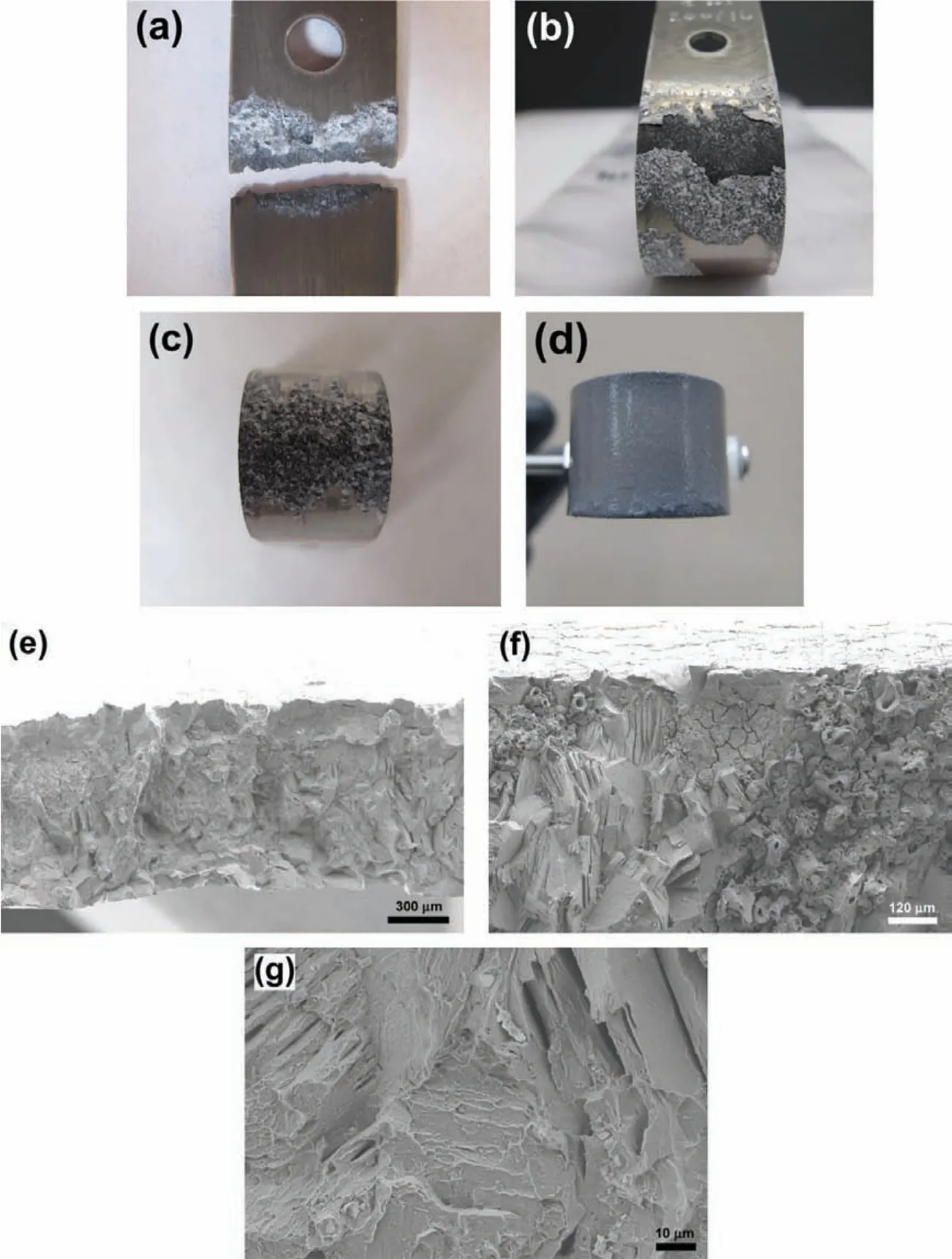
Fig.13.EV31A sample in different heat treatment conditions which were applied the potential and current in different regions from Fig.11(unstressed plot)in 0.1 M NaOH solution with 80 ppm Cl−;(a)EV31A peak-aged(Eapp=1.6 VAg/AgCl:transpassive potential),(b)EV31A peak-aged(Eapp=−0.2 VAg/AgCl:passive region),(c)EV31A as-received(Eapp=−1.0 VAg/AgCl:active/passive region),(d)EV31A as-received(iapp=−10 mA/cm2:galvanostatic condition at hydrogen charge region),(e)cross-sectional view of WE43C peak-aged(Eapp=1.6 VAg/AgCl:transpassive potential),(f)mixed mode of fracture of WE43C peak-aged,and(g)transgranular mode of WE43C peak-aged.

Fig.14.XRD patterns of EV31A as-received specimen under galvanostatic condition at hydrogen charge region(applied current=−10 mA/cm2);(a)Tension side,and(b)Compression side.
In order to understand if the metastable state of the passivation behavior of Mg-RE alloys leads to SCC,potentials within the transition zones were applied to the U-bend specimens and the SCC behavior was investigated.Fig.13 shows images of post tested EV31A samples in different heat treatment conditions and different bias potentials in 0.1 M NaOH solution containing 80 ppm Cl−.Fig.13(a)shows the failure of EV31A in peak-aged condition under an applied potential of 1.6 VAg/AgCl(transpassive potential).The EV31A-PA sample failed by localized corrosion of the arms of U-bend specimen adjacent to the solution/vapor interface.There was no evidence of cracking at the strained region of the U-bend specimen.Therefore,it is shown that application of potential associated with zone-1 resulted in localized corrosion but not SCC.When the applied potential was−0.2 VAg/AgCl(passive region,zone-2),EV31A peak aged specimen showed uniform corrosion of the curved area,as seen in Fig.13(b).Severe pitting corrosion occurred at the strained surface of the EV31AAR specimen when the applied potential was−1.0 VAg/AgCl(potential in zone-2),as seen in Fig.13(c).When the applied potential was in the cathodic region,no localized corrosion or cracking could be observed.The EV31A as-received specimen was cathodically polarized under galvanostatic condition at a current density of−10 mA/cm2that evolved hydrogen on the U-bend specimen surface.No crack initiation was observed even after 340 h under the cathodically polarized hydrogen evolution condition.Fig.13(d)shows the specimen surface after the galvanostatic cathodic polarization after 340 h.The edges of the specimen were observed to be attacked possibly due to dissolution of MgH2phases that formed during the cathodic polarization.The formation of MgH2was confirme by the XRD analysis as shown in Fig.14.MgH2peaks were present on both tension side and compressive side of the specimen.Formation of the MgH2phase did not result in crack initiation on the specimen.Fig.13(e)shows the cross-sectional area of WE43C peak-aged sample after SCC at the applied potential of 1.6 VAg/AgCl(transpassive potential,zone-1).At this high potential hydrogen will be oxidized to protons.Diffusion/drifting of H+inside the surface layer will be difficul because of the uphill electric field Therefore,failure of the WE43C-PA under this high anodic potential would occur only by the fil rupture and anodic dissolution process.Hydrogen may not be associated with this EAC.However,flut like features,and cleavage type fracture pointed out that hydrogen could be involved in this high anodic potential also.Application of high anodic potential caused accelerated SCC failure compared to the OCP condition.It could be seen that the sample failed in mixed modes(TGSCC+IGSCC).However,each fracture mode was uniformly distributed throughout the cross section.It was different from the samples failed by EAC at OCP(Figs.7(a),and 10(a))which had quite clear zones of separate intergranular and transgranular fracture modes.From Fig.13(f),attack on specifi crystallographic planes(that appears as TGSCC)could be observed next to the intergranular fracture.In addition,the evidence of intergranular corrosion attack on the cracked region could be seen.Fig.13(g)revealed transgranular fracture mode with the decohesion of precipitates.
EV31A showed mostly localized corrosion under applied anodic potentials,whereas,WE43C-PA specimen showed mixed mode cracking under anodic potential in the transpassive region.These results indicated that both f lm rupture and hydrogen adsorption were responsible for the EAC of Mg-RE alloys.Re-precipitated corrosion products were observed on the fracture surfaces.
3.6.Effect of cathodic polarization
Cathodic polarization resulted in formation of MgH2but did not initiate EAC.In order to understand the effect of passive layer on the hydrogen evolution,cathodic polarization was carried out on the unstressed Mg-RE alloy coupons that were covered with surface layers.Initially the samples were conditioned at the open circuit condition in 0.1 M NaOH solution for 48 h.A thick passive layer formed on the specimen surfaces during this OCP conditioning period.These samples were then potentiostatically passivated at 0.5 VAg/AgClfor 1 h.Potentiodynamic polarization was carried out on these surface fil covered specimens from OCP to−2.0 VAg/AgClat a scan rate of−1 mV/s.Exchange current density for hydrogen evolution,and Tafel slope of the hydrogen evolution reaction(HER)were determined from the cathodic polarization plots and summarized in Table 3.For comparison,the results of cathodic polarization of freshly polished specimens are also included.The results indicated that presence of Mg(OH)2layer helped increase the exchange current density for the HER.Enhanced hydrogen evolution on the hydroxide covered magnesium was reported by other researchers[40,41].However,the Tafel slopes were higher on the surface oxide covered specimens than the Tafel slopes of freshly polished specimens.Fig.15(a)-(d)shows the SEM images of the specimens after cathodic polarization.EV31A in as-received and peak-aged conditions showed significan amount of surface crack initiation on the surface fil after cathodic polarization as seen in Fig.15(a)and(b),while EV31A overaged and WE43C peak-aged specimens did not have cracks on the surface(Fig.15(c)and(d)).The cracking tendency of the surface fil of EV31A could not be related to the HER electrochemical parameters.The blisters present on the surface fil would help hydrogen diffuse into the bulk of the specimen.Otherwise,in the presence of a surface layer,the diffusion of hydrogen into the specimen thickness would be slower,because atomic hydrogen cannot diffuse through Mg(OH)2and the diffusion will be in the form of H+[42].
The accelerated failure of WE43C peak aged specimen at a high anodic potential of 1.6 VAg/AgCl,and longer failuretime or no-failure at cathodic potentials of EV31A peak aged specimens suggest that the EAC of Mg-RE alloys is determined by the stability of the surface layer of the alloys.Therefore,f lm rupture and dissolution could be the crack initiation mechanism.Once cracks initiated,the crack propagation was assisted by the hydrogen adsorption which reduced the surface energy of the crystallographic planes.Table 4 summarizes failure modes and time to failure of all specimens in the experiment.

Table 3Summary of the cathodic polarization results of the unstressed specimens.
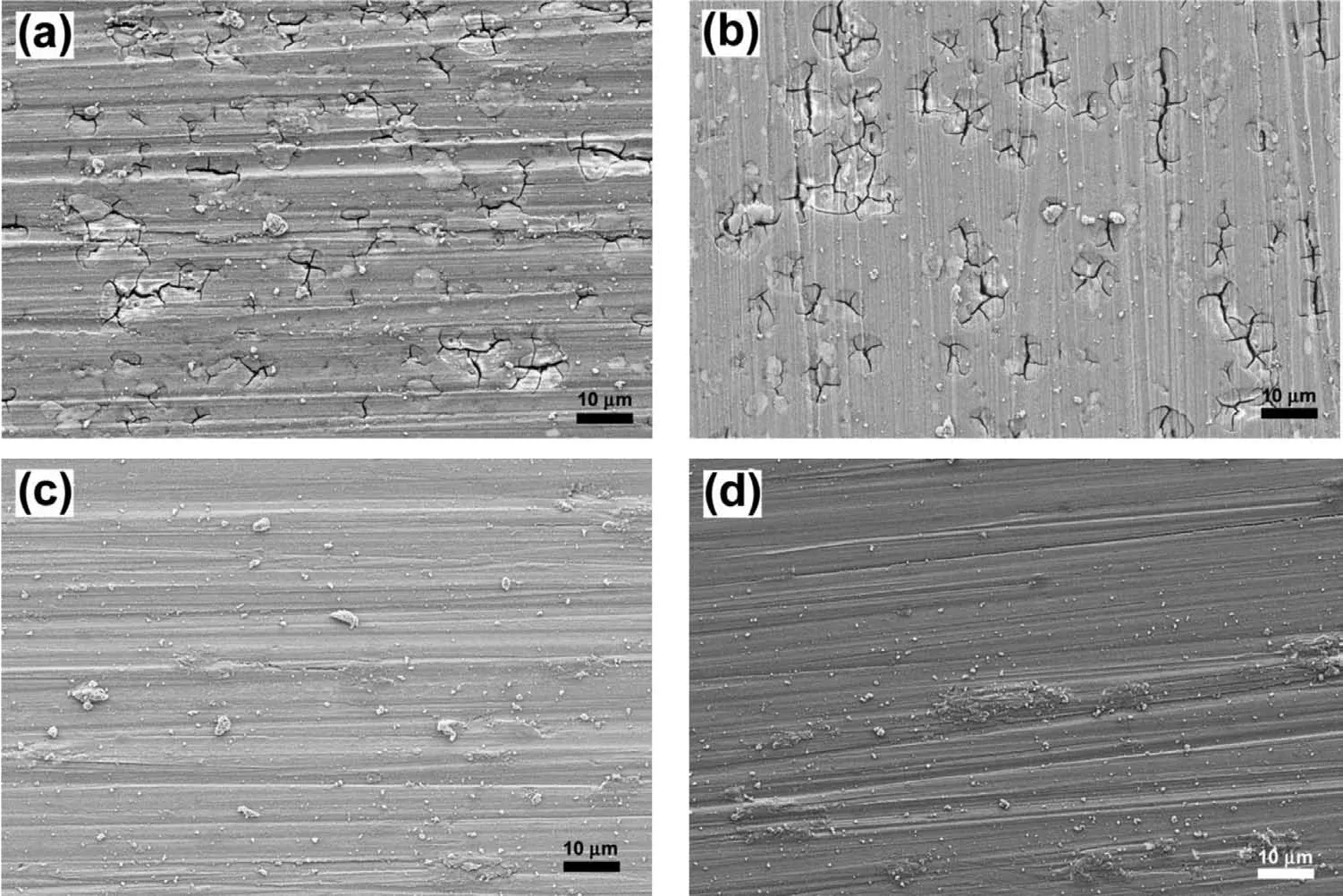
Fig.15.SEM images of the unstressed specimens which were measured OCP for 48 h,followed by passivation for 1 h,and cathodic polarization in 0.1 M NaOH solution without chloride;(a)EV31A as-received,(b)EV31A peak-aged,(c)EV31A overaged,and(d)WE43C peak-aged.
3.7.General discussion
Overall,the EV31A alloy was susceptible to EAC at OCP in all the heat treated conditions(AR,PA,and OA)in 0.1 M NaOH+80 ppm Cl−solution at room temperature.EAC failure was not generally observed under anodic or cathodic external bias conditions.The WE43C alloy failed by EAC only in the peak aged condition.The EAC of WE43C-PA occurred at OCP and anodic bias(1.6 VAg/AgCl)conditions.The specimens of WE43C-AR did not show cracking at OCP in 80,100,and 200 ppm chloride containing 0.1 M NaOH solution at room temperature.The increase in the chloride concentration did not result in the EAC,but promoted pitting in the Mg-RE alloys.Similar observations have been reported for chloride induced SCC of austenitic stainless steels[43].A competition between localized corrosion and SCC is considered to occur under the investigated conditions.If the rate of localized dissolution was higher than the rate of crack growth,the dissolution process masked the SCC.The absence of cracks on the predominantly pitting specimen could be attributed to the specifi electrochemical conditions,and relaxation of the stress due to the dissolution.The absence of cracking during the cathodic charging of EV31A-AR specimens in the 80 ppm Cl−(pH∼13)solution could also be attributed to the stress relaxation because of dissolution of MgH2phases in the electrolyte.It is well documented that MgH2is a strong reducer and is not stable in water.
It is reported that more stable oxide layer consisting of alloying additions such as Nd,and Zr in the Mg-RE alloys than the Mg(OH)2type film observed on the Mg-Al alloys[44].Our previous results indicated that the passive layer formed on the WE43C(Mg-Y-Nd-Gd-Zr)alloy wasrelatively thinner than the layer formed on the EV31A(Mg-Nd-Gd-Zn-Zr)alloy[27].The ex-situ analyses of the surface film showed incorporation of rare earth elements in the native oxide/hydroxide layers and presence of RE2O3phase as well[27].The composition and heat treatment conditions of the two Mg-RE investigated did not alter the nature of surface layers significantl.The fluctuation in the OCP indicated unstable conditions prevailed on the U-bend specimens.The stability of the surface layer could be speculated based on the Asaro-Tiller-Grinfiel instability criterion[45,46].The threshold stress(σth)required to destabilize the passivity could be expressed as[47]:

Table 4Summary of failure mode and time to failure of the specimens.

where,E=elastic modulus,γ=surface energy,h0=thickness of surface film
The slip step dissolution mechanism proposed for the SCC of austenitic stainless steel may not be directly applicable to Mg-RE alloys.The reduction in the stacking fault energy(SFE)of austenitic stainless will result in the formation of planar(dislocation arrays)slip steps that help disrupt the passive fil while emerging out[48].On the other hand,addition of rare earth elements(especially Gd,and Y that have high solubility in Mg)decreases the SFE of Mg which in turn promotes slip in the pyramidal planes.Therefore,reduction in the SFE of Mg may lead to formation of fine slip steps which may not be effective in breaking the passive layer when they emerge out during the deformation.The reported higher SCC resistance of the Mg-RE alloys could be associated with the increased number of slip systems.Furthermore,Mg-RE alloys show enhanced creep resistance due to pinning of dislocations by the fin secondary phase precipitates,and increase in the out-of-plane vacancy migration energy barrier[49].Vacancies created during dissolution of crack tip could increase the creep strain and enhance the SCC.A correlation between steady-state creep rate and SCC failure time was reported for austenitic stainless steels[50].Anodic dissolution of Mg and Mg-Al alloys such as AM50 and AZ91D in 3.5% NaCl resulted in enhanced creep strain and creep rupture[51].It should be noted that localized anodic dissolution of U-bend specimens would result in stress relaxation because of the fi ed strain condition,when the vacancies(created by the dissolution process)interact with the dislocations and increase the creep strain.If the stress level of the U-bend specimens relaxes below a threshold level,no EAC could be observed.However,the dissolution process could lead to fluctuation of the OCP.
The role of hydrogen cannot be ignored in the EAC of Mg alloys because the OCP of Mg alloys is so low that hydrogen evolves even under anodically polarized condition up to−0.566 VAg/AgClin the pH 13 solution.Therefore,EAC of Mg-RE specimens was associated with hydrogen assisted cracking.The flut like features seen on the fracture surfaces suggest that adsorption induced dislocation emission(AIDE)could be a possible mechanism[37].Interestingly,the flut like features,and cleavage fracture planes were observed on the fracture surface of WE43C-PA failed at+1.6 VAg/AgCl.The possibility of hydrogen involvement in this condition could be speculated based on the defect structure of the surface layer formed during anodic polarization of WE43C-PA.Anodic polarization leads to formation of MgO fil on the surface and water molecules are incorporated in this film Incorporation of H2O in the MgO results in inclusion of one oxygen in the lattice which implicitly creates one Mg vacancy(VMg”).This defect reaction could be written as:

Here,VMg”is double negatively charged,and OH·is single positively charged which makes the compound defect(OH·VMg”HO·)a neutral one as proposed by King and Freund[52].The OH·is formed because two protons(2H+)diffuse into the MgO to compensate for the magnesium vacancy(VMg”).The linear neutral defect(OH·VMg”HO·)may be unstable and undergo the conversion[52]:

The H2molecule is weakly adsorbed at the cation vacancy sites,and evolve out leaving behind the cation vacancies.The evolved H2will be oxidized to protons at high potentials.The increase in the anodic polarization would create more cation vacancies.The hydrogen formed inherently inside the surface fil could also diffuse to the oxide/metal interface and participate in the adsorption induced dislocation emission mechanism.The above reactions could result in the NDE and observed fractographic features at high anodic potentials.
The SSRT tests showed SCC susceptibility of Mg-RE alloys in widely different environments such as distilled water[7],0.1 M NaCl saturated with Mg(OH)2[6,8],and body flui[9].Since a protective surface layer was not stable in these environments(due to pH and dynamic loading conditions),the embrittlement was mainly attributed to hydrogen assisted cracking.The failures under open circuit conditions and cathodically polarized conditions showed similar results[9].On the other hand,in this study,U-bend specimens in high pH environments showed passivity and the EAC behavior was influence by the stability of the surface layer.No cracks were observed in the 0.1 M NaOH solution(without any chloride)because of a more stable surface layer which showed a stable OCP profile External anodic bias in the transpassive potential range accelerated the EAC,while cathodic polarization showed no EAC in spite of hydride formation.
4.Conclusions
SCC tests were carried out on the U-bend specimens of EV31A and WE43C Mg-RE alloys in 0.1 M NaOH solution with the addition of 80,100,and 200 ppm Cl−at room temperature under open circuit potential(OCP)and applied potentials.SCC was observed only in the 80 ppm chloride containing solution.Based on the experimental results,the following conclusions can be drawn:
1.EAC of Mg-RE alloys is determined by the stability of the surface layer of the alloys.No cracks were observed on the specimens tested in 0.1 M NaOH solution due to a stable surface film The crack initiation in 80 ppm chloride environment was associated with the f lm rupture and anodic dissolution mechanism while the crack propagation was possibly influence by the hydrogen adsorption induced dislocation emission mechanism.
2.Peak aged EV31A,and WE43C specimens were susceptible to SCC under open circuit condition.Overaged specimens had the highest EAC resistance.SCC of EV31A and WE43C revealed both intergranular and transgranular cracking modes.
3.Increasing the chloride concentration did not increase the susceptibility to EAC.On the other hand,the tendency to localized corrosion increased with chloride concentration.
4.Applied anodic potential in the metastable passive regions caused localized corrosion of EV31A specimens.An applied potential of 1.6 VAg/AgClcaused accelerated failure of the WE43C peak aged specimen.
5.OCPs of EV31A and WE43C decreased gradually when cracks initiated,and propagated.The OCP versus time(V−t)profil can be used for monitoring the SCC failure of Mg-RE alloy components in real life service conditions.
Declaration of Competing Interest
The authors declare that they have no known competing financia interests or personal relationships that could have appeared to influenc the work reported in this paper.
Acknowledgments
J.Ninlachart acknowledges the support by Royal Thai Navy.Mg-RE alloys investigated in this study were donated by Magnesium Elektron N.A.Inc.
杂志排行
Journal of Magnesium and Alloys的其它文章
- Microstructural evolution of Mg-Al-Re alloy reinforced with alumina fiber
- Predicting and controlling interfacial microstructure of magnesium/aluminum bimetallic structures for improved interfacial bonding
- Plasma electrolytic oxidation of AZ31 and AZ91 magnesium alloys:Comparison of coatings formation mechanism
- Effects of annealing treatment on microstructure and tensile behavior of the Mg-Zn-Y-Nd alloy
- Microstructure and performance of biodegradable magnesium alloy tubes fabricated by local-heating-assisted dieless drawing
- Comparisons of microstructure homogeneity,texture and mechanical properties of AZ80 magnesium alloy fabricated by annular channel angular extrusion and backward extrusion
