Macro-physical fiel of large diameter magnesium alloy billet electromagnetic direct-chill casting:A comparative study
2020-12-18YonghuiJiaXingruiChenQichiLeHangWangLeiBao
Yonghui Jia,Xingrui Chen,Qichi Le,Hang Wang,Lei Bao
Key Laboratory of Electromagnetic Processing of Materials,Ministry of Education,Northeastern University,314 Mailbox,Shenyang 110819,People’s
Republic of China
Received 11 November 2019;received in revised form 5 January 2020;accepted 4 March 2020 Available online 25 June 2020
Abstract A comprehensive two-dimensional axisymmetric mathematical model that couples transient electromagnetic force with flui fl w,heat transfer,and solidificatio was established to describe the interaction of multiphysics fiel during DC casting.The melt f ow,heat transfer,and solidificatio characteristics under differential phase pulse magnetic fiel and differential phase low-frequency electromagnetic fiel(DP-PMF and DP-LFEF)were numerically investigated by means of numerical simulation during electromagnetic direct-chill(DC)casting of AZ31 alloy at the same casting conditions.The effects of differential phase electromagnetic field on Lorentz forces distributions,melt f ow,heat transfer,and liquid sump shape were discussed systematically.Based on measured current waveform,the results were compared with those obtained without magnetic fiel(MF)and under conventional pulse magnetic fiel(PMF)and low-frequency electromagnetic fiel(LFEF)under the same conditions.The results show that the application of magnetic field can significantl change the solidificatio process of DC casting.Differential phase magnetic field(DP-LFEF and DP-PMF)can effectively reduce the temperature of the melt in the liquid sump,and the shallower liquid sump depth can be obtained under the differential phase magnetic fields A large velocity vibration amplitude and a lower temperature are available simultaneously under DP-PMF,resulting in more uniform temperature distribution.© 2020 Published by Elsevier B.V.on behalf of Chongqing University.This is an open access article under the CC BY-NC-ND license.(http://creativecommons.org/licenses/by-nc-nd/4.0/)Peer review under responsibility of Chongqing University
Keywords:Magnesium alloy;Differential phase magnetic field Low-frequency magnetic field Heat transfer;Direct-chill casting;Numerical simulation.
1.Introduction
Magnesium and its alloys have a good application prospect in automotive,military,and aerospace industries where weight-relieving requirements are continuously increasing for reducing the cost or energy consumption,because of its advantageous properties like low density,good castability and abundant deposits in the earth[1,2].Direct-chill(DC)casting is widely used in the production of aluminum alloy,magnesium alloy,and copper alloy semi-finishe products[3,4]because of its simplicity and robust nature[5].However,the magnesium alloys billets produced by conventional DC casting technique usually exhibit coarser structures,poor surface quality,and element segregation,et al.,especially for largesize billets,resulting in poor deformability and mechanical properties[6,7].Many research finding revealed that applying external fields such as ultrasonic fiel and electromagnetic field is an effective method to improve the metallurgical quality of billets during DC casting[8-11].Due to the advantages of contactless and no pollution,low cost,and easy operation,the application of electromagnetic field in solidifi cation has caused widespread concern;electromagnetic fields such as low-frequency electromagnetic field pulse magnetic field AC and DC combined magnetic field et al.,have been widely used in DC casting process[12-14].
It has been recognized that whenever flui f ow is artifi cially applied during the casting of alloys,some changes in the microstructure can be observed[15-17].In particular,the forced convection generated by magnetic fiel during solidificatio has profound effects on the solidificatio structure.Moreover,magnetic fiel differs significantl for different applications.The application of low-frequency electromagnetic field can effectively reduce element segregation and refin grains;it has been proven that as-cast grains of most alloys can be refine under pulse electromagnetic fields furthermore,differential phase alternating magnetic fiel is advantageous for improving surface quality and grains refine ment.Guo et al.applied alternating magnetic fiel in the semi-continuous casting of AZ91 magnesium alloy,found that microstructures of billet changed from columnar dendrites to equiaxed dendrites and its uniformity increased[18].Similarly,Zuo and Li et al.studied the solidifie structures of ZK60 alloy and aluminum alloys in the presence of a lowfrequency electromagnetic field found that the grains were fine and had a more uniform spherical shape,and elements distributions were more uniform[19,20].Fu et al.found that in the presence of pulse magnetic fiel during solidification the as-cast microstructure was significantl refine andα-Mg was modifie from developed dendrite to fin rosette[21].Research showed that the pulse magnetic fiel treatment can refin grains of Mg-7Zn alloy and reduce the MgZn phase volume fraction[22].
It is noteworthy that all of the above magnetic field can affect the solidificatio structure and refin the grains.Although the researchers have extensively studied the interaction between the solidificatio process and molten melt in each magnetic fiel through numerical simulations and experimental studies[3,23-25],the essential associations among these magnetic field are poorly elucidated.Due to the magnetic fiel period is much smaller than the momentum response time of the melt,most current numerical simulation studies use the time-average value of Lorentz force to couple the melt solidificatio process.Using the implicit finit difference method,Bondareva et al.[26]investigated the effect of inclined magnetic fiel on natural convection melting in a square cavity with a local heat source and analyzed the natural convection heat transfer combined with melting process.Jia at al.studied the distribution characteristics of transient Lorentz forces generated by low-frequency magnetic field pulse magnetic field differential phase low-frequency magnetic field and differential phase pulse magnetic field predicting the effects of each magnetic fiel on melt f ow[27].However,the f ow fiel and temperature distribution were not carried out.Chen et al.numerically studied the solidificatio characteristics of Al-5wt.% Cu alloy under a typical pulse magnetic field and the results compared with those obtained with harmonic magnetic fiel[28].But the differential phase electromagnetic field were not taken into consideration.
In this paper,a comprehensive two-dimensional axisymmetric mathematical model that couples transient electromagnetic force with flui f ow,heat transfer and solidificatio was established to describe the interaction of multiphysics fiel during DC casting.The melt f ow and solidificatio characteristics under differential phase pulse magnetic fiel and low-frequency electromagnetic fiel(DP-PMF and DPLFEF)were systematically investigated,and the results compared with those under conventional low-frequency and pulse electromagnetic fiel(LFEF and PMF)and in the absence of magnetic fiel(MF).
2.Numerical analysis strategies
2.1.Simulation model and methods
The DC casting apparatus with electromagnetic fiel is shown in Fig.1(a).It mainly includes melt feed control and distributor device,metal melt,mold,cooling water,and excitation coils.The electromagnetic force(Lorentz force)will agitate the liquid metal,resulting in the transportation of mass,momentum,and energy during solidification The principle of differential phase current generation and how it is applied in DC casting process have been described in detail in previous studies(see in ref.[27]).Because the geometry is centrosymmetric,the model was built in therOzpalne of cylindrical coordinate system.A two-dimensional axisymmetric geometry model was established and only half of the domain was considered in present simulations,as shown in Figs.1(b)and(c).AZ31 alloy was chosen as the material of the melt in present simulations.The nominal alloy composition is 2.79wt.% Al,0.74wt.% Zn,and 0.31wt.% Mn with Mg to balance.COMSOL multiphysics software,a finit element analysis solver and multiphysics simulation software,was used to couple electromagnetic field with flui f ow and solidification The numerical simulation procedures are shown in Fig.2.
In order to investigate the solidificatio characteristics of AZ31 alloy under differential phase electromagnetic field fi e cases were considered in the present simulations.In the firs case,no external magnetic fiel(conventional DC casting)was applied,and the molten metal was postulated to solidify under natural convection caused by the thermal buoyancy.In the second and third cases,low-frequency alternating currents without(conventional LFEF)and with 90° phase difference(DP-LFEF)were fed to the coils,resulting in solidificatio under the LFEF and DP-LFEF,respectively,the molten metal was postulated to solidify under the convection caused by the thermal buoyancy and Lorentz forces.In the fourth and fift cases,pulse currents(conventional PMF)and with 90°phase difference(DP-PMF)were fed to the coils,resulting in solidificatio under the PMF and DP-PMF,respectively.The alternating current with a peak of 143 A and the frequency of 20Hz was employed to generate low-frequency magnetic field the equations of low-frequency excitation currents were shown in Eqs.(1)and(2).The pulse current with setting value of 80 A,the frequency of 20Hz,and the duty cycle of 20%was used to generate pulse magnetic field the f tting equations of pulse excitation current were shown in Eqs.(3)and(4).
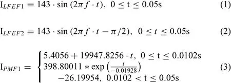
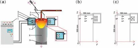
Fig.1.Schematic of the DC casting apparatus with electromagnetic field(a and the geometry model of differential phase(b)and conventional electromagnetic fiel(c)used in the present simulations;1-electromagnetic control system,2-coil1,3-coil2,4-casting crystallizer,5-metal delivery tube,6-feed control and distributor,7-cooling water,8-billet,9-dummy bar.
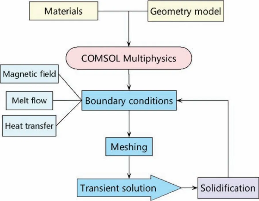
Fig.2.Numerical simulation procedure for the coupling of electromagnetic field with flui fl w,heat transfer,and solidification

2.2.Simplificatio and assumption of simulation model
In this work,some necessary model simplificatio and assumptions are given as follows:
(1)Joule heat is not considered in this model.
(2)The meniscus shape and the calculation of solute fiel are not included in the present simulations.
(3)The molten metal behaves as an incompressible fluid and the density is a constant.
(4)The thermal buoyancy is included in this model.The
Boussinesq approximation is applied to simulations where the flui varies in temperature from one place to another,driving a f ow of flui and heat transfer.It is expressed as:Fthernal=ρgβ(T−T0),whereρandβare the density and volume expansion coefficien of the molten metal,respectively;T0is the reference temperature(878K).
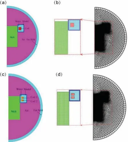
Fig.3.Geometry model(a)and meshes(b)for single-phase magnetic field geometry model(c)and meshes(d)for differential phase magnetic fiel used in the present simulations.
2.3.Simulation electromagnetic fiel
The calculation model for electromagnetic fiel is shown in Fig.3.It consists of cylindrical billet with electrical conductivity(σ)and relative magnetic permeability(μ),round multiturn coil with define time-varying current I(t)(Eqs.(1)∼(4)),cooling crystallizer model and air zone.Physical properties and dimension of model used in the electromagneticsimulations are shown in Table 1.Magnetic fiel distribution in the molten metal during DC electromagnetic casting process was obtained by solving the Maxwell equations(Eqs.(5)∼(8))and constitutive relations of the isotropic linear medium(Eqs.(9)∼(11)).

Table 1Physical properties and dimension of model used in the electromagnetic simulations.
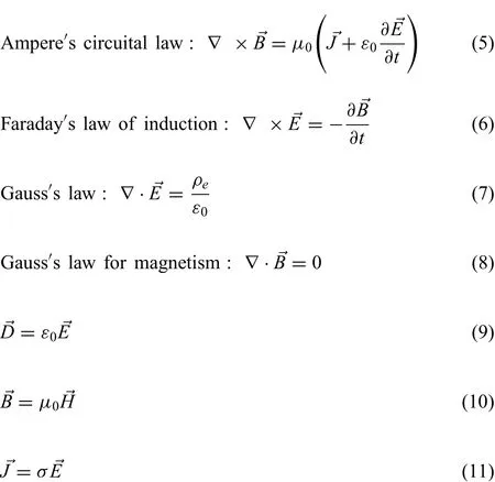
The above equations were solved by the vector potential method based on the finit element method with Eqs.(12)and(13).

Based on above solutions,Lorentz force→Fcan be calculated by Eq.(14).

Where,→Bis magnetic flu density vector,μ0is magnetic permeability,→Jis conduction current density vector,ε0is permittivity,→Eis electric fiel intensity vector,ρeis electric charge density,→Dis electric flu density vector,→His magnetic fiel density vector,σis electrical conductivity,→Ais magnetic potential vector,φis electrical potential,→Fis Lorentz force vector,andtis time.
2.4.Modeling of melt flo and solidificatio
2.4.1.Governing equations
In this work,the governing equations for conservation of momentum and the continuity equation for conservation of mass were adapted from those given by Zhang et al.[29],a single-zone model was used in metal fl w and solidifica tion.The model equations can be integrated across the entire zone without the need to explicitly subdivide the domain into solid,liquid,and mushy regions.The turbulence effects were modeled by a standard two-equationk-εmodel with realizability constraints based on Reynolds-averaged Navier-Stokes(RANS)equations.

Continuity equation(Eq.(15)):Momentum equations(Eq.(16)isr-direction;Eq.(17)isz-direction):
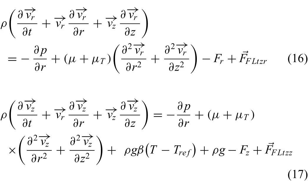
Where,ρis density,μis dynamic viscosity,pis pressure,μTis turbulent viscosity,−→vrand−→vzare therandzcomponents of velocity,respectively;gis acceleration of gravity,Trefis reference temperature,Tis temperature,→FFLtzrand→FFLtzzare Lorentz forcer-component andz-component,respectively.The role of the source terms(FrandFz)is to dampen the velocity at the phase-change interface so that it becomes that of the solidifie phase after the transition.

Whereflrepresents the volume fraction of the liquid phase;Amushand∈represent arbitrary constants;→Ucastis the velocity of the cast billet.
Turbulent kinetic energy equation(Eq.(20)):

Turbulent energy dissipation equation(Eq.(21)):

The turbulent viscosityutused in the momentum equations was estimated by Eq.(22),and wherepkcan be expressed as Eq.(23):

Energy equation(Eq.(24)):

In the present simulations,the energy transport during the solidificatio process was accurately simulated by equivalent specifi heat method.The equivalent specifi heat(Ceff)is expressed as Eqs.(25)and(26):

The liquid fraction and solid fraction were modeled by a function of temperature(Eq.(27)),where solid fraction was written as Eq.(28).

Where,kis turbulent kinetic energy,εis turbulent dissipation rate,Cpis the flui heat capacity at constant pressure.Lis latent heat,fsis solid phase fraction,Tsis solidus,andTlis liquidus.The equations also consist of some adjustable constants:σk=1.0,σε=1.3,cε1=1.44,cε2=1.92 andcμ=0.09.
2.4.2.Boundary conditions and physical properties
Heat transfer boundaries shown in Fig.4 includes symmetric boundary,inlet,free surface,primary cooling,secondary cooling,and outlet.Boundary conditions and relevant parameters used in fl w and temperature field simulations are shown in Table 2.Physical properties of the melt and thermal conditions for the solidificatio simulations exhibit in Table 3.
3.Model validation
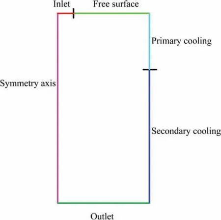
Fig.4.Heat transfer boundaries of DC casting.
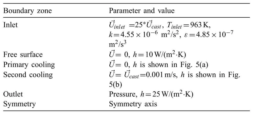
Table 2Boundary conditions and relevant parameters used in f ow and temperature field simulations.
The model used in the present simulation has been validated in the author's previous researches.The magnetic flu density under pulse magnetic fiel in the DC casting mold with an inner diameter of 300mm were measured three times,and the results were compared with the simulation results,which shows a good agreement between the simulated and experimental results[30].Furthermore,with reference to the mold structure used in the real DC casting production,under the same casting conditions and process parameters,a corresponding melt fl w model under a magnetic fiel is established,and the shape of liquid sump(the solid/liquid interface shape)at stable casting stage predicted by the model was compared with the experimental data that measured during DC casting in factory;the results indicate that calculation data by the model agree with experimental data[31].
Grid size is an important factor affecting simulation accuracy and computation complexity,which determines whether the simulation process converge or not.Four different grid sizes(4mm,6mm,8mm,and 10mm)for the melt were used to verify the sensitivity of the mesh in this work.The numerical simulation results show that grid sizes have little effect on the magnetic flu density distribution and temperature variation in molten melt,as shown in Fig.7.Moreover,as the mesh size decreases,the temperature fluctuatio amplitude of the melt gradually decreases during casting(Fig.7(b)),which means more accurate calculation results,and the effects of mesh sizes on calculation results are further reduced.When the maximum mesh size is larger than 10mm,the calculation does not converge.When the maximum mesh size is less than 4mm,the calculation is complex,and it will take a lot of time and huge storage space.Therefore,the maximum mesh size is 4mm in the current simulations.
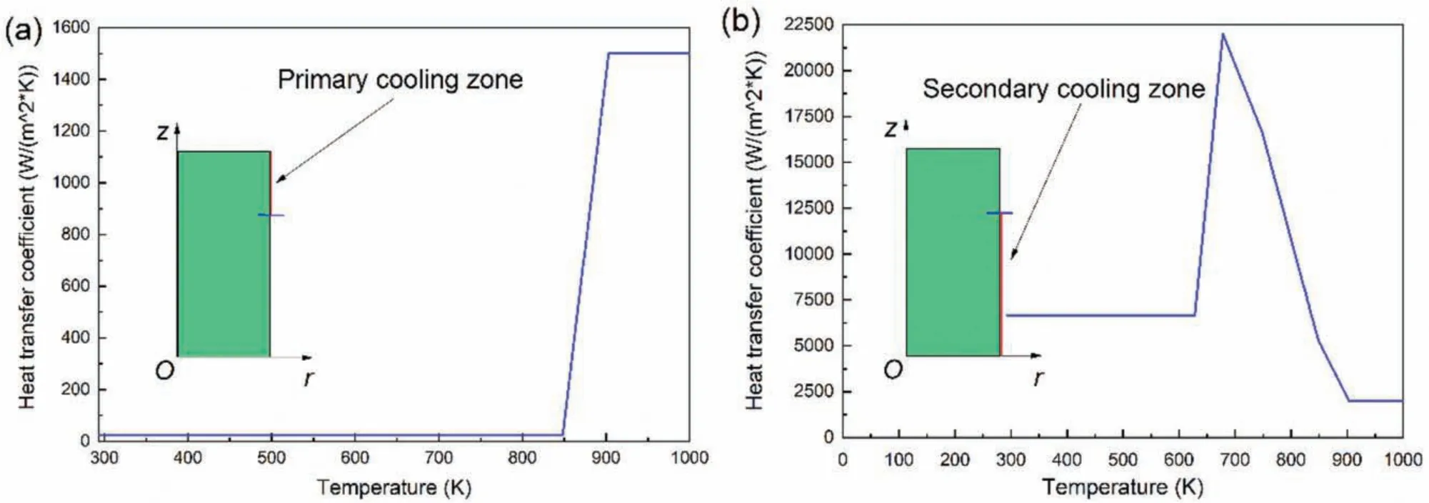
Fig.5.Heat transfer coefficien(h)of primary cooling(a)and secondary cooling(b)vs.temperature used in the present simulations.

Fig.6.Specifi heat(a)and thermal conductivity(b)of AZ31 magnesium alloy.
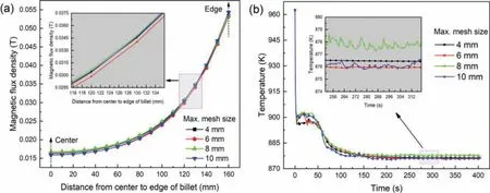
Fig.7.Magnetic flu density(→B)along a radius(the line where points a,b,and c are located in Fig.1)(a);variations of melt temperature during solidificatio under different mesh sizes(b).
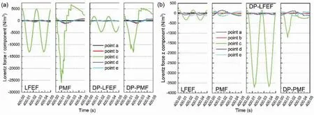
Fig.8.Lorentz force r(a)and z(b)components at points a∼e(in Fig.1)in one cycle.

Table 3Physical properties of the melt and thermal conditions for the solidificatio simulations.
4.Results and discussion
4.1.Lorentz force distribution
The radial component of Lorentz force(rcomponent)can alleviate the contact pressure between the melt and mold,forming an electromagnetic soft contact[32].The values of Lorentz forces change periodically with the periodic variations of low-frequency and pulse current,acting on the melt convection and vibration.The changes of axial component of Lorentz force(zcomponent)contribute to melt forced convection.Figs.8(a)and(b)show therandzcomponents of Lorentz force at the different points(points a,b,c,d,and e in Fig.1)in one cycle.It is evident that Lorentz forcercomponents of four types of magnetic field are larger thanzcomponent under the same electromagnetic condition.In particular,Lorentz forcercomponents of the LFEF and PMF are much greater than that of DP-LFEF and DP-PMF,which means Lorentz forcercomponent dominant the melt f ow modality.In the presence of LFEF and PMF,the direction of Lorentz force is mainly perpendicular to the casting direction and points to the center of melt or the mold wall,leading to radial shearing and oscillation actions on the melt.However,Lorentz forcezcomponents of differential phase magnetic field(DPLFEF and DP-PMF)are larger than that of LFEF and PMF,and Lorentz forcezcomponents of DP-LFEF and DP-PMF mainly point to the front of solid/liquid(S/L)interface.It means that in the presence of differential phase magnetic fields both Lorentz forcercomponent andzcomponent drive and control melt f ow.Under the circumstances,both forced convection and vibration can be produced in the molten melt,and the forced convection effects are stronger than those under a single coil LFEF and PMF,while their vibration effects are weaker.
Fig.9(a)and(b)show the Lorentz force distribution along radial and axial direction of billet passing through point c in Fig.1.It can be seen from Fig.9(a)that there exists an edge zone with a higher Lorentz force at 40mm from the mold wall.Lorentz force induced by PMF is larger than DP-PMF,LFEF,and DP-LFEF;Lorentz forces induced by differential phase magnetic field(DP-LFEF and DP-PMF)are larger than that induced by the single-phase magnetic field(LFEF and PMF).Maximum Lorentz force of PMF is about twice that of the DP-PMF and LFEF,and is about fourth times that of the DP-LFEF,and the Lorentz forces are close to zero from 1/2R(R,radius)to the center of billet.Furthermore,Lorentz force along axial direction frst increases and then decreases from liquid level of the molten melt,as shown in Fig.9(b).Lorentz forces in primary cooling zone are larger,and the maximum Lorentz force appears in the center of primary cooling zone.
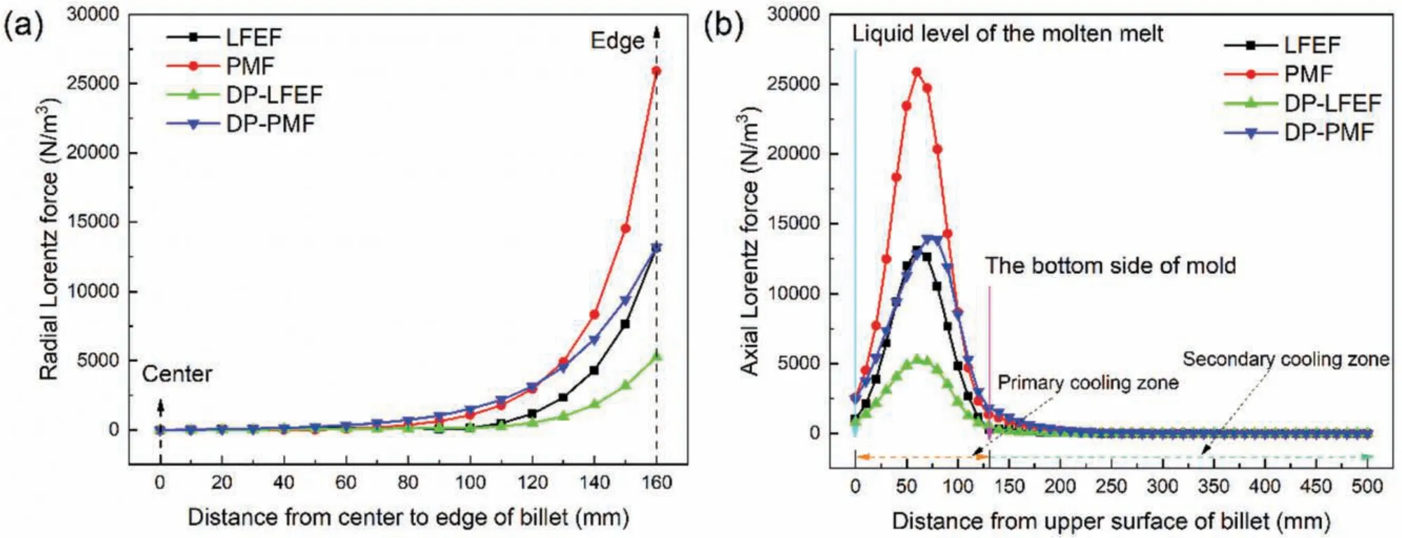
Fig.9.Lorentz forces along the radial(a)and axial direction(b)passing through point c in Fig.1.
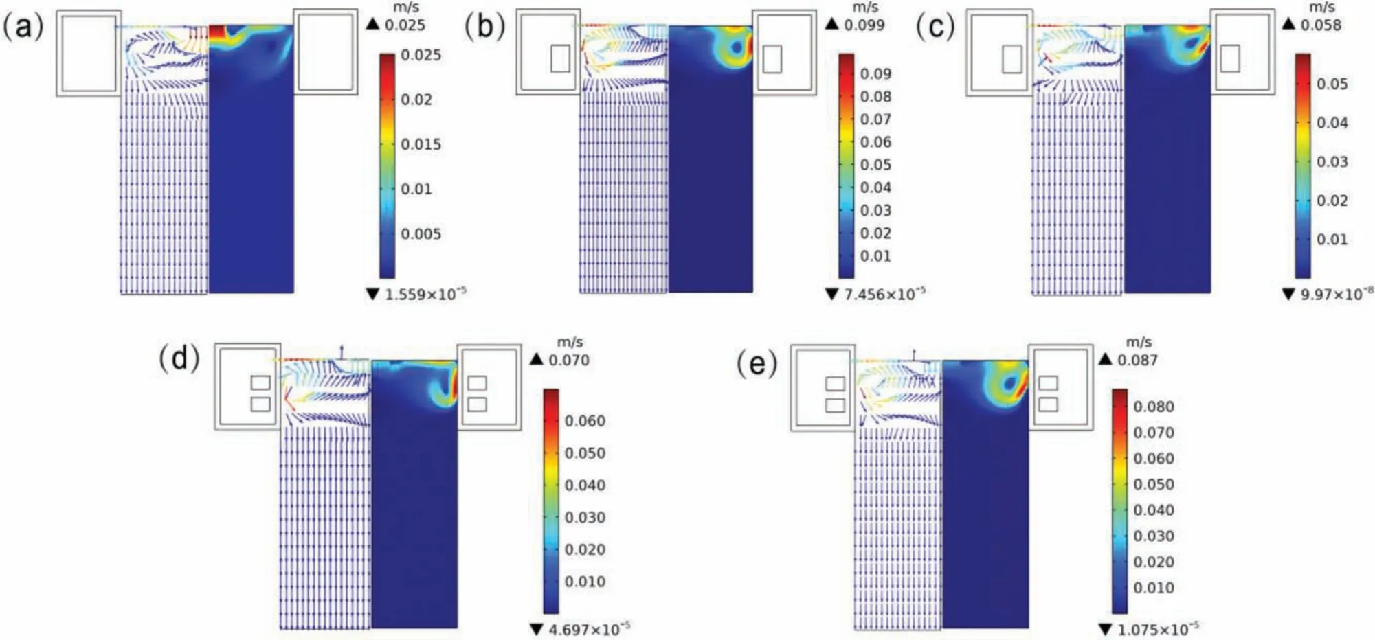
Fig.10.Velocity vectors and profile patterns in the absence of magnetic fiel(a)and in the presence of LFEF(b),PMF(c),DP-LFEF(d),and DP-PMF(e).
4.2.Characteristics of melt flo
Fig.10(a)-(e)shows the velocity vectors and profile patterns under different forms of magnetic field respectively.It can be found that in the absence of MF,the maximum f ow velocity mainly concentrated in the center of liquid sump.However,the higher velocity is near the upper surface of the melt and edge of billet in the presence of MF,and the maximum f ow velocities are 0.099m/s(LFEF),0.058m/s(PMF),0.070m/s(DP-LFEF),and 0.087m/s(DP-PMF),respectively,which are much larger than that in the absence of MF(0.025m/s).Moreover,in the presence of LEFE or DPLFEF,larger fl w velocity area is virtually contiguous with the mold wall,as shown in Fig.10(b)and(d).In the presence of PMF or DP-PMF,an angle is formed between larger fl w velocity area and mold wall,as shown in Fig.10(c)and(d).The reason for this is that the force convection generated by MF can significantl change the f ow condition,and characteristics of heat transfer and extraction of the melt are inseparable from these phenomena.
Fig.11 shows the variations of streamlines in the absence of MF,and in the presence of LFEF,PMF,DP-LFEF,and DPPMF in specifi moment at the stable stage of casting process.It is noteworthy that fl w status of the melt is constant in the absence of MF,and the inside melt of liquid sump forms a constantly changing large circulation area in the presence of MF.When the electromagnetic field are applied,the changes of fl w status of the melt in liquid sump under low-frequency electromagnetic field(LFEF and DP-LFEF)are more dramatic than that under pulse electromagnetic field(PMF and DP-PMF).Curiously,under pulse electromagnetic field(PMF and DP-PMF),the variations of the direction of melt f ow velocity near the solid/liquid interface are more frequent,and the angle between the velocity near the solid/liquid interface and the mold is larger than that under low-frequency electromagnetic fields which means that the more strengthen convection induced by pulse electromagnetic field leads to faster heat extraction near the mold,increasing the solid fraction of melt near the mold.Furthermore,in the presence of conventional electromagnetic field(LFEF and PMF),the variations of velocity near the center of liquid sump are more obvious,and in the presence of differential electromagnetic field(DPLFEF and DP-PMF),the variations of velocity near the edge of liquid sump are more obvious.
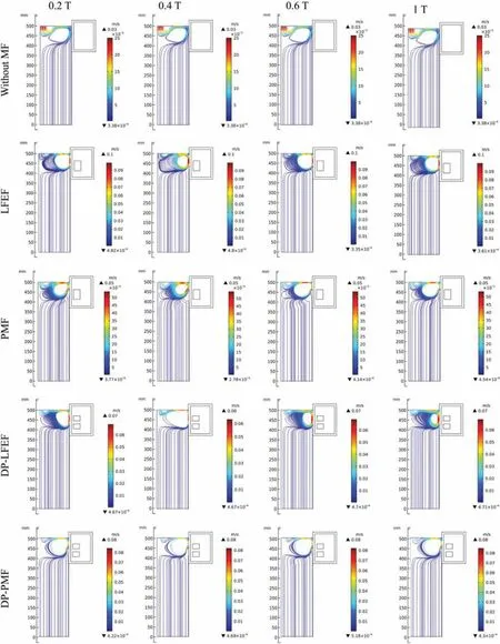
Fig.11.The variations of streamlines in the absence of MF(a),and in the presence of LFEF(b),PMF(c),DP-LFEF(d),and DP-PMF(e)in specifi moment(0.2T,0.4T,0.6T,and 1T)at the stable casting stage.
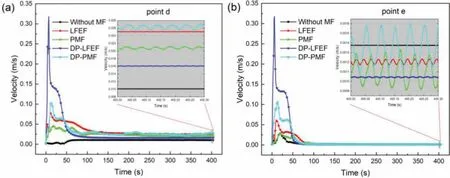
Fig.12.Variations of melt velocity near the liquid level(a)and S/L interface(b).
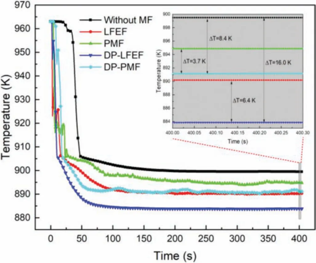
Fig.13.Variations of melt temperature in the liquid sump(at point b in Fig 0.1)under different forms of magnetic fields
The growth of the nucleated grain is determined to a large extent by the composition of the melt ahead of the S/L interface[33].In the real solidificatio process,an accumulation of solute elements usually occurs at the S/L interface,which depends on the alloy compositions and on the solidificatio conditions(solute diffusion and melt convection).Hence,the casting conditions(e.g.,melt velocity and temperature gradient)play an important role in the fina solidifie structures.Research[34]suggests that the local heat transfer at the S/L interface controls the dendrite growth;when the forced convection increases,the main vertical stem gradually tend to tilt toward the upstream direction.Simultaneously,the“washing effect”occurring in the mushy zone near the S/L interface is propitious to solute transportation.Fig.12(a)and(b)shows the variations of melt velocity near the liquid level and S/L interface,respectively.It can be seen that whether near the S/L interface or liquid level,the fl w velocity is constant,consistent with the result of streamlines in Fig.11.With the application of magnetic fields variations of the melt velocity approximate sinusoidal fluctuation Fluctuation ranges of the velocity under PMF and DP-PMF are larger than those in the presence of LFEF and DP-LFEF.Near the liquid level(at point d in Fig.1),the sequence of velocity is:DP-PMF>LFEF>PMF>DP-LFEF>without MF.The reason for this is that in the absence of magnetic field the melt f ow is mainly natural convection,and the driving force derives from the kinetic energy of melt pouring into the mold.However,forced convection became predominant in the melt f ow in the presence of magnetic fields As previous mentioned in Section 4.1,the sequence of Lorentz forces induced by different forms electromagnetic fiel at point d is consistent with the velocities results.Near the S/L interface(at point e in Fig.1),fluctuatio ranges of the velocity under pulse electromagnetic field(PMF and DP-PMF)are larger than that under low-frequency electromagnetic field(LFEF and DPLFEF),which can effectively inhibit solute concentration.Research indicates that in real casting process,convection can accelerate solute transportation[35].When forced convection induced by magnetic field assists mass transport,the formation of a steady-state solute diffusion zone is generally rapid,and an extended solute diffusion zone may develop quickly,which may result in a faster grain growth,according to the solute-suppressed nucleation concept,and in fine grain sizes in commercial alloys[35,36].When pulse magnetic field are applied,the amplitude of fluctuatio of velocity under DPPMF is slightly greater than that in the presence PMF,which is diametrically opposed to the effect of low-frequency magnetic fields This is mainly due to the natural convection or forced convection induced by thermal buoyancy or Lorentz force,and the differences of solid fraction under different forms magnetic fields
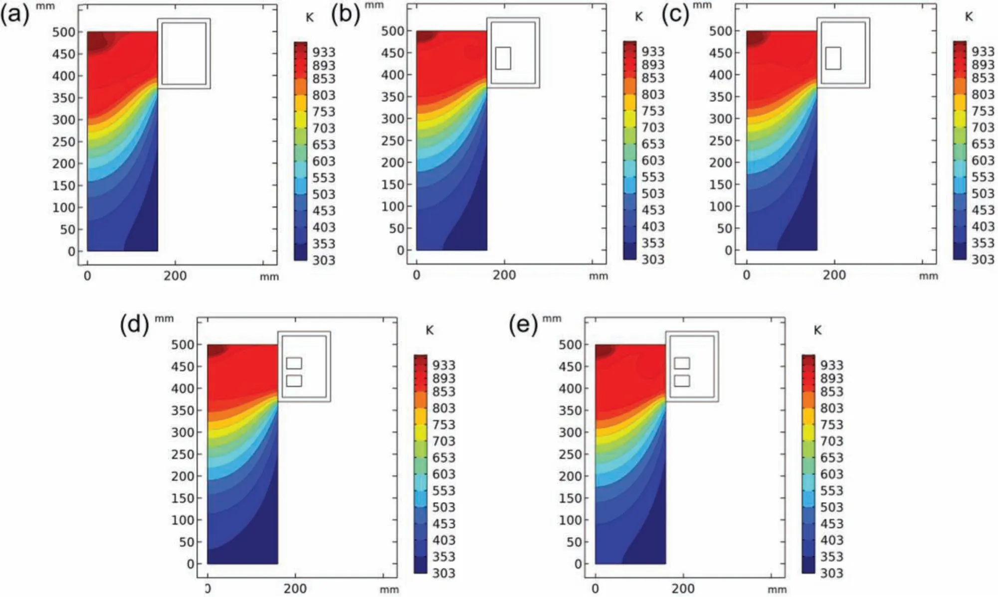
Fig.14.Temperature fiel distributions under different forms of magnetic field at the stable casting stage,including without MF(a),LFEF(b),PMF(c),DP-LFEF(d),and DP-PMF(e).
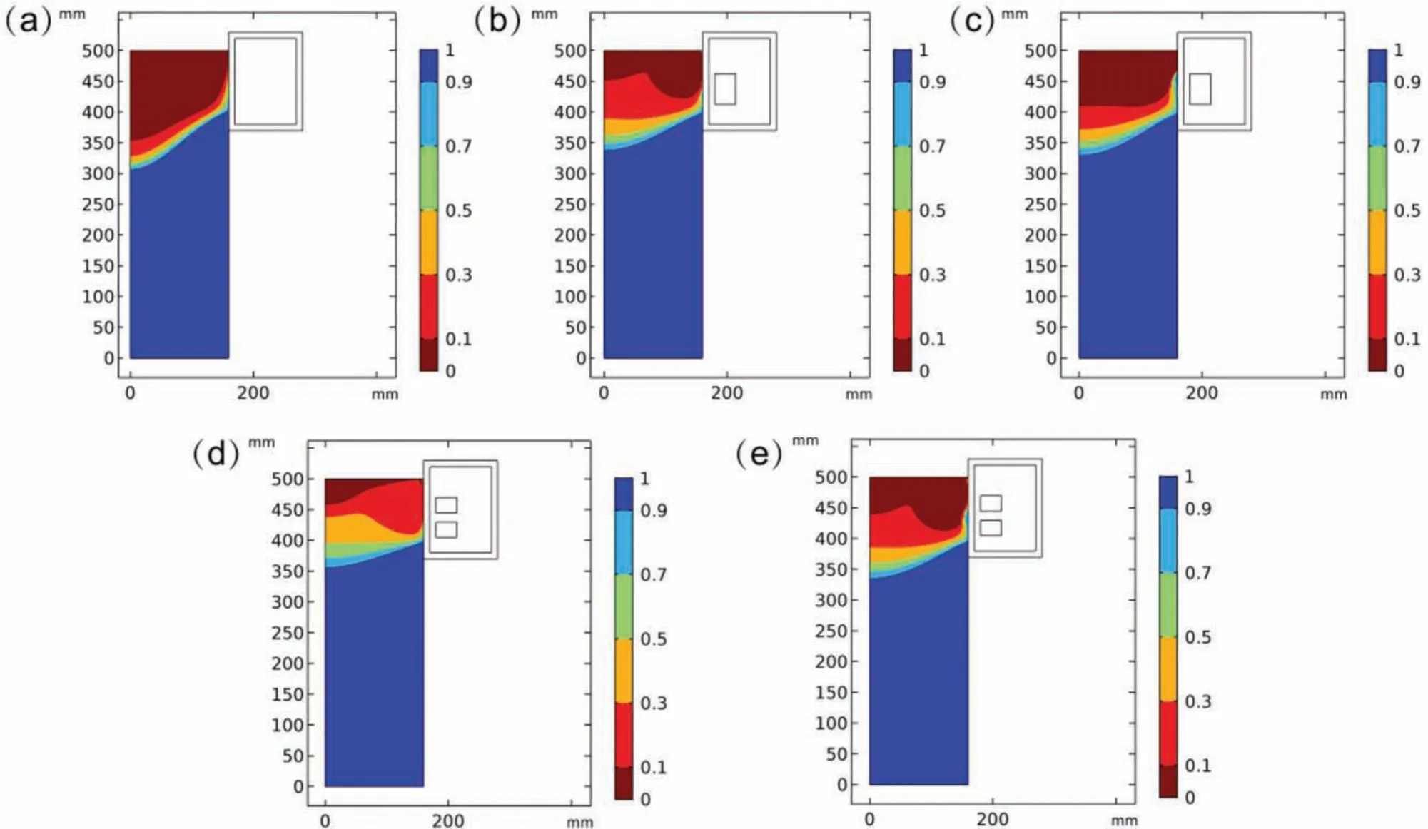
Fig.15.Solid fraction distributions under different forms of magnetic field at the stable casting process,including without MF(a),LFEF(b),PMF(c),DP-LFEF(d),and DP-PMF(e).
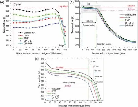
Fig.16.Radial distribution(a)and axial distribution((b)and(c))of temperature through point b.
4.3.Temperature fiel and solidificatio
In Fig.13,variations of melt temperature in the liquid sump(at point b in Fig 0.1)under different types of magnetic field were extracted from the melt pouring into the crystallizer to the stable casting stage.In the present simulations,the stage before stable casting does not represent the start-up stage in the real DC casting process.This study focuses on the macro-physics field(e.g.,velocity,temperature,and solidification at the“stable”casting stage,which is closely linked with the fina solidifie structures of billet.The forced convection and vibration induced by external forces result in a more rapid heat transfer and cooling rate.It can be seen from Fig.13 that the temperature of melt decreases obviously in the presence of magnetic fields and the temperatures under differential phase magnetic field are lower than that in the presence of single-phase magnetic fields Under low-frequency magnetic fields the temperature difference between DP-LFEF and LFEF is 6.4K;under pulse magnetic fields the temperature difference between DP-PMF and PMF is 3.7K.Compared with no magnetic field temperatures of the melt under DP-PMF and DP-LFEF reduce by 8.4K and 16.0K,respectively.As nucleation mainly occurs at the beginning and early stage of solidification a lower temperature is conducive for the nuclei to avoid remelting and survive in the bulk melt[28].
Figs.14 and 15 show the temperature and solid fraction distributions under different forms of magnetic field at the“stable”casting stage,which are closely associated with nucleation.It is evident that with the application of magnetic fields temperature fiel and shape of S/L interface change apparently.Compared with single-phase magnetic fields high temperature areas in liquid sump are obviously reduced in the presence of differential phase magnetic fields especially on the upper surface of melt.As shown in Fig.15,in the cases of pulse magnetic fields solid fractions near the mold are larger than that in the cases of low-frequency magnetic fields Therefore,due to the solidificatio shrinkage,the efficien y of heat extraction near the mold decreases,which means that a stronger forced convection can be obtained by applying pulse magnetic fields This is the reason why the temperatures under pulse magnetic field at point b in Fig.1 are higher than that in the presence of low-frequency magnetic fields In the case of PMF or DP-PMF,appropriate reduction of current intensity is conductive to the heat transfer near the mold.Furthermore,it is obvious that a larger temperature gradient along axial direction of billet can be obtained,and solid fraction in liquid sump increases under differential phase magnetic fields The higher and more uniform solid fraction results in higher and more uniform nucleation number,which can improve the effectiveness of the grain refinin throughout the solidificatio process of melt[29].
In Fig.16,more quantitative temperature distributions along a radius at half height of excitation coil(the line where points a,b,and c are located)were extracted at the“stable”casting stage in the f ve cases of LFEF,DP-LFEF,PMF,and DP-PMF.In the presence of magnetic fields the temperature of melt decreases,and the temperature uniformity increases,as shown in Fig.16(a).As a whole,temperature uniformity under low-frequency magnetic field is superior to that under pulse magnetic fields temperature uniformity under differential phase magnetic field is superior to that under single-phase magnetic fields Furthermore,it can be seen that whether under low-frequency magnetic field or pulse magnetic fields the melt temperatures under differential phase magnetic field are slightly higher than that under low-frequency magnetic field at the edge of billet(near the mold),which means that differential phase magnetic fiel is an effective method to improve the temperature distribution of liquid sump in DC casting.The reason for this may be that with the application of differential phase magnetic field Lorentz forcezcomponent increases significantl,and both Lorentz forcercomponent andzcomponent act together on melt fl w,as shown in Fig.8 mentioned in Section 4.1.A uniform temperature fiel is beneficia to the synchronous nucleation throughout the melt,which prevents the rapid growth of individual grains[28].In addition,according to the temperature distribution along axial direction(the line where points d,b,and e are located),the depth of liquid sump decreases under magnetic fields and the depths of liquid sump under DP-LFEF(135mm)and DP-PMF(150mm)are less than that under LFEF(145mm)and PMF(152.6mm),less than that in the absence of MF(155.5mm).
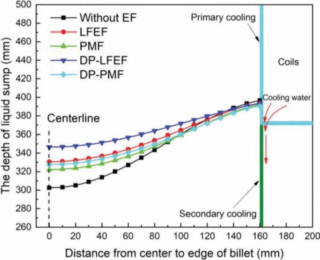
Fig.17.Shapes of liquid sump in different forms of magnetic field at the stable casting process.
Furthermore,shapes of the liquid sump in different types of magnetic field at the stable casting process were obtained,as shown in Fig.17.The changes of liquid sump shapes are dramatic,and the shapes of liquid sump become smoother from the center to the edge of billet,and solidi move somewhat upward in the presence of magnetic fields which means the lower temperature gradient along the cross-section of billet.Lower temperature gradient along the horizontal cross-section of liquid sump and shallower liquid sump could promote the grain refinemen and the formation of equiaxed grains[37].
5.Conclusions
In this paper,a comprehensive two-dimensional axisymmetric mathematical model was established to describe the interaction of transient electromagnetic force,flui f ow,heat transfer,and solidificatio multiphysics fiel during DC casting.The characteristics of melt f ow and solidificatio under LFEF,DP-LFEF,PMF,and DP-PMF were systematically investigated for AZ31 magnesium alloy billet casting.The following conclusions have been drawn:
(1)In differential phase magnetic fields a larger Lorentz forcezcomponent can be obtained.Under LFEF and PMF,Lorentz forcedrcomponent plays a dominant role in forced convection;under DP-LFEF and DP-PMF,Lorentz forcerandzcomponents jointly drive melt convection.
(2)Compared with the conventional DC casting(without MF)and the casting under the single-phase magnetic fiel(LFEF and PMF),the application of differential phase magnetic field(DP-LFEF and DP-PMF)can effectively reduce the temperature of the melt in the liquid sump during DC casting.
(3)In the presence of DP-PMF,a large velocity vibration amplitude and a lower temperature are available simultaneously,resulting in more uniform temperature distribution.
(4)The application of MFs can obviously change the liquid sump shape in the solidificatio process,and the shallower liquid sump depth can be obtained under the differential phase magnetic field
Acknowledgment
This study was financiall supported by the National Natural Science Foundation of China(51974082),the National Natural Science Foundation of China(51771043),and the Programme of Introducing Talents of Discipline Innovation to Universities 2.0(the 111 Project 2.0 of China,No.BP0719037).
杂志排行
Journal of Magnesium and Alloys的其它文章
- Microstructural evolution of Mg-Al-Re alloy reinforced with alumina fiber
- Predicting and controlling interfacial microstructure of magnesium/aluminum bimetallic structures for improved interfacial bonding
- Plasma electrolytic oxidation of AZ31 and AZ91 magnesium alloys:Comparison of coatings formation mechanism
- Effects of annealing treatment on microstructure and tensile behavior of the Mg-Zn-Y-Nd alloy
- Microstructure and performance of biodegradable magnesium alloy tubes fabricated by local-heating-assisted dieless drawing
- Comparisons of microstructure homogeneity,texture and mechanical properties of AZ80 magnesium alloy fabricated by annular channel angular extrusion and backward extrusion
