POD analysis on vortical structures in MVG wake by Liutex core line identification *
2020-12-02XiangruiDongXiaoshuCaiYinlinDongChaoqunLiu
Xiang-rui Dong , Xiao-shu Cai , Yinlin Dong, Chaoqun Liu
1.School of Energy and Power Engineering, University of Shanghai for Science and Technology, Shanghai 200093,China
2.Key Laboratory of Multiphase Flow and Heat Transfer in Shanghai Power Engineering, Shanghai 200093, China
3.Department of Mathematics, University of Central Arkansas, Conway 72035, USA
4.Department of Mathematics, University of Texas at Arlington, Arlington 76019, USA
Abstract: The Liutex core line method, first combined with the snapshot proper orthogonal decomposition (POD), is utilized in a supersonic micro-vortex generator (MVG) wake flow at Ma=2.5 and Reθ=5760 to reveal the physical significance of each POD mode of the flow field.Compared with other scalar-based vortex identification methods, the Liutex core line identification is verified to be the most appropriate approach that is threshold-free and provides full information of a fluid rotation motion.Meanwhile, the Liutex integration is employed to quantitatively track the evolution of the vortices in MVG wake and is applied to the determination of the effective control section of the MVG wake for the optimization study of MVG design.The physical mechanism of each POD mode for multi-scale and multi-frequency vortical structures is investigated by using Liutex core line identification to give some revelations.For the mean mode (mode 0) indicating the time-averaged velocity flowfield of the MVG wake flow, a pair of primary counter-rotating streamwise vortices and another pair of secondary vortices is uniquely identified by two pairs of Liutex core lines with Liutex magnitude.In contrast, mode 1 is featured by a fluctuated roll-up motion of streamwise vortex, and the streamwise component of the MVG wake is demonstrated to be dominant in terms of the total kinetic energy contribution.Meanwhile, a dominant shedding frequency of St=0.072 is detected from the temporal behavior of mode 2, which has the organized arc-shaped vortex structures shedding from MVG induced by the K-H instability.Additionally, mode 4 subjects to low-frequency oscillations of the wall vortices and thus takes a relatively lower frequency of St=0.044.
Key words: Proper orthogonal decomposition (POD), vortex identification, Liutex, vortex core lines, micro-vortex generator (MVG)
Introduction
Flows such as turbulent boundary layers,blunt-wakes, jets, and separated flows are dominantly characterized by some coherent structures with various spatial and temporal scales, which are posited to be responsible for significant portions in mass and heat transfer, turbulent mixing, flow noises and aerodynamic drag, etc., and thus, these flow structures are always considered the major objective of flow control and optimal design for aircraft designers.In particular, for supersonic flows, the presence of unsteady and viscous effects such as shock waves,turbulence, and their interactions may lead to flow distortion, flow separation or aerodynamic force fluctuations, resulting in the performance of aircraft deteriorating and causing body oscillation.As a convenient and effective passive device for most control of shock-induced flow separation, microvortex generator (MVG) is of particular interest in many industrial applications.Due to its importance in both scientific research and engineering applications,many efforts on the study of the control mechanism of the MVG wake and the distinct coherent structures(vortices) have been devoted over the past decades.Coherent structures are organized with large-scale structures that persistently appear, disappear, and reappear with a characteristic temporal lifespan,although they are not explicitly steady in space or time[1].They also play an important role in random and chaotic fluctuations with small scales, due to the redistribution and partitioning of the turbulent kinetic energy.Thus, it is obvious that a complete and precise description of the characteristics of canonical coherent structures is vital to deeper understand the physics of predicting and controlling their evolution in supersonic flows.Babinsky et al.[2]suggested a schematic illustration of the various vortices in MVG wake by their experimental study that a small horseshoe vortex,a pair of primary streamwise vortices, a pair of secondary vortices originating from the side-wall and another pair of secondary vortices originating from the top edges of the ramp are typical in coherent features of the MVG wake.However, a different conceptual model of the vortical organization evolution behind the micro-ramp was given by Li and Liu[3].They noted that the streamwise vortices could generate initially behind MVG, but decay in a short time and become rather weak further downstream.However,the curved shear layer around the wake quickly becomes unstable and induces the K-H vortices, and eventually develops into the vortex rings further downstream.
In recent decades, some remarkable numerical and experimental high-resolution techniques, such as direct numerical simulation (DNS), large eddy simulation (LES) and time-resolved particle image velocimetry (TR-PIV) have been widely applied to the accurate capture of unsteady flows at reasonable spatial and temporal resolutions[4].It seems highly feasible to extract the salient coherent structures from numerous numerical and experimental information.Such multi-dominant coherent motions, however,bring many challenges in identifying the spatiotemporal characteristics of each category of coherent structure.Many identification techniques proposed during the last several decades have been demonstrated to receive some successes in identifying the coherent structures.According to Lugt[5], Robinson[6],an intuitive existence of a vortex can be verified by closed or spiraling streamlines or path lines in fluid flow.However, the streamlines or path lines are not Galilean invariant and thus cannot be used for vortex identification.A critical point theory was proposed by Chong and Perry[7]to judge the presence of the local rotational motions.If the velocity gradient tensor of a three dimensional flow field has a pair of complex conjugate eigenvalues, the instantaneous streamline pattern presents a local swirling motion around the axis of the real eigenvector.The concept of the vorticity concentration and other vorticity-based methods[8-9], which are considered as the first generation (1G) of vortex identification methods, were widely accepted by many researchers since the vorticity vector was deemed to provide a mathematical definition of fluid rotation motions.Zhou and Antonia[10]employed the spatially phase-correlated vorticity to characterize large-scale organized structures in a cylinder wake, but it runs into serious problems in most viscous flows, particularly in turbulent flows.The fact is that the vorticity cannot distinguish a vortical region with rotational motions from a strong shear layer[11].Concerning this issue,several scalar-based vortex identification criteria, such asQ[12],λ2[13],λci[14],Ω[15], etc., have been prompted and extensively applied in many fields, and these criteria are regarded as the second generation(2G) of vortex identification methods.However,Qandλ2are restrictive for vortex identification for compressible flows due to their incompressibility hypothesis.Additionally, for most scalar-based vortex identification criteria, the sensitivity to the threshold change provides a large amount of difficulties in making a judgment to define the boundary of vortical structures[15-16].As pointed out by Liu et al.[17], these eigenvalue-based criteria, similar to the vorticity based ones, can also be severely contaminated by the shearing effect.In our previous work, a novel eigenvector-based method named Liutex/Rortex[17-19]was thus proposed to address this issue.As a systematical definition of the local fluid rotation,Liutex can provide the scalar, vector and tensor interpretations.The scalar magnitude of Liutex represents the local rotational strength and the direction of the Liutex vector denotes the local rotation axis, and the Liutex tensor represents the real rotational part of the velocity gradient tensor.In this situation, a systematical expression including Liutex magnitude iso-surface, Liutex vector field and Liutex lines are of interest for vortex identification in fluid mechanics.Moreover, a normalized Liutex method[20-21]combining the ideas of theΩmethod was proposed to represent the relative strength of the fluid rotation motion for alleviating the sensitivity of the threshold.Recently, Liu et al.[22]summarized the main idea of the third generation (3G) of vortex identification methods based on Liutex, and first presented six core issues of vortex definition including(1) the absolute strength, (2) the relative strength, (3)the rotation axis, (4) the vortex core center, (5) the vortex core size, and (6) the vortex boundary.Aiming at the fourth issue above, the vortex core center can be described by Liutex interpretation that the overlapping Liutex is the center of the vortex core if the Liutex iso-surface size reduces to a line.Thus, the Liutex core line, which is defined as a line where the Liutex magnitude gradient vector is aligned with the Liutex vector, was proposed to extract core features[23], and then its automatic identification was carried out by Xu et al.[24].Detailed expression for the Liutex definition will be covered later.
The vortex identification methods mentioned above have been extensively applied to determine the common characteristics of the vortices in both fundamental research and engineering applications.However, their availability and advantages may be eroded for some flows superimposed with multi-dominant coherent vortex structures concerned with spatiotemporal features and fluid dynamics issues.One way to approach the spatiotemporal features of multi-scale coherent structures in a precise and unbiased fashion is to take advantage of the proper orthogonal decomposition.Proper orthogonal decomposition (POD) was first utilized in turbulent flows by Lumley[25]to decompose the multi-scale coherent structures into spatial modes with various energy levels and its successful application was later confirmed in various areas of fluid mechanics, such as coherent structures in a turbulent boundary layer[26],Couette flow[27], circular cylinder wake[28-29], jet flow[30-32], laminar separation boundary layer[33]and MVG controlled compression ramp flow[34], etc..Meyer et al.[30]analyzed the instantaneous velocity field of a turbulent jet in crossflow from stereoscopic PIV snapshots by using POD, and indicated that the wake vortex structures, rather than the jet shear layer vortices, are the dominant dynamic-structures responsible for the strong interaction with the jet core.Cavar and Meyer[32]identified the coherent structures of a turbulent jet in cross flow through POD algorithm and revealed that the relationship between the counter-rotating vortex pair, the hanging vortex and the wake vortices could be illustrated by the first two POD modes.They also indicated that the shedding process involving oscillation of the jet core is responsible for the creation of wake vortices.There are also some POD studies focusing on exploring the essence of the complicated spatiotemporal structures in the supersonic or hypersonic flows.Yang and Fu[35]extracted the flow structures in supersonic plane mixing layers from DNS data with the aid of the POD method and pointed out the main difference between the incompressible and compressible mixing layers in terms of the frequency spectrum of POD modes.The leading POD modes represent most of the turbulence energy for incompressible flow, while, much more high-ordered POD modes are needed accounting for the total energy for compressible flow.For a NACA0015 foil wake flow obtained by TR-PIV,Prothin et al.[36]applied POD analysis to highlight the unsteady nature of the wake flow using phase averaging based on the leading ordered POD coefficients to characterize the coherent process in the near wake of the rudder.Berry et al.[37]applied POD on time-resolved schlieren to extract the canonical flow structures in supersonic multi-stream rectangular jets and indicated that it is an effective approach for the identification of the flow physics that dominate these modern military nozzles.The buzz phenomenon of a typical supersonic inlet was numerically analyzed by Luo et al.[38]using POD, and their study suggested that the dominant flow patterns and characteristics of the buzzed flow are obtained by decoupling the computed pressure field into spatial and temporal sub-parts.Moreover, the first mode represents the mean features and dominates the global flow field,while the second mode reflects the dominant frequency characteristics of buzz.
To date, there have been many numerical and experimental studies on identifying the wake structures of MVG[39]and exploring its physical mechanism of flow control[2,40-41], especially concerning the optimal geometry of MVG to obtain more effective and efficient alleviation of flow separation or shock[42-44].However, the lack of a rigorous vortex definition inevitably is the primary obstacle to precisely identify the vortical structures of MVG wake from other structures (e.g., noises, shock waves,strong shear structures, nonphysical fake vortex structures, etc.), and thus leads to some inconsistencies and contradictions on understanding the corresponding mechanisms in fluid dynamics and flow control technique.In this study, the Liutex system proposed in our previous publications, is applied in a supersonic MVG wake flow with multi-scale vortical structures for the vortex identification as well as the quantitative analysis.Unfortunately, the works on the mode decomposition of the MVG wake flow with multi-scale vortical structures have received little attention with very few publications.Therefore, a systematical POD analysis on the MVG wake is carried out to give some revelations.Meanwhile, the Liutex core line method is first applied to provide a distinct approach to illustrate each POD eigenmode.
1.Numerical algorithm and case description
For most supersonic turbulent flows with shock problems, the conventional WENO scheme can capture the shock, but cannot perform well in turbulence simulation due to the overmuch viscous dissipation effect.Therefore, a bandwidth-optimized fifth order WENO scheme[40]is utilized to discretize the convective terms of the compressible Navier-Stokes equations in this study.For viscous terms,considering the conservative form of the governing equations, the fourth order central difference scheme is used twice to discretize the second order derivatives.For the discretization of time terms, the explicit third order total variation diminishing (TVD) Runge-Kutta scheme is adopted for the temporal terms.
Dimensions of the computational domain with a MVG are shown in Fig.1.The axesx,yandzare in the spanwise, wall-normal and streamwise directions respectively, and the corner of MVG is located atx=0.The configuration of MVG follows the optimization study of Anderson et al.[42], which setsα=24°,c=7.2handh=4 mm , wherehdenotes the height of MVG.The declining angle of the trailing edge behind MVG is set to70° to alleviate the difficulty of grid generation.The grid of the computational domain isnx×ny×nz=137× 192× 1600.The details of the grid generation and the convergence analysis can refer to the previous researches[45].
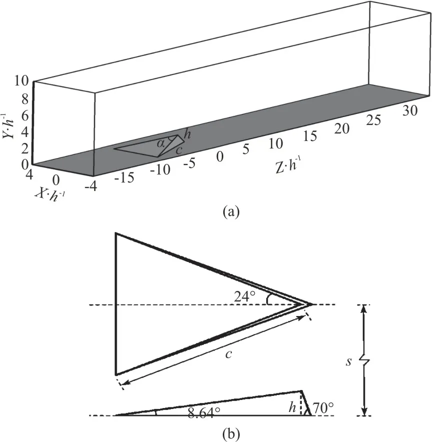
Fig.1 Configurations of (a) The computational domain and (b)MVG geometry
For the inflow boundary, 20000 instantaneous turbulent profiles from our previous DNS simulation results[46], are adopted to obtain the fully developed turbulent inflow boundary condition.The top boundary is set as a far-field boundary condition and the outlet boundary is set as the outgoing flow without reflection.The adiabatic, zero-pressure gradient and non-slipping conditions are adopted for the wall boundary conditions.The front and rear boundaries in the spanwise direction are set as periodic boundary conditions.Furthermore, the initial parameters of the turbulent flow are listed in Table 1, whereReθis the Reynolds number based on the momentum thicknessθandδis the undisturbed turbulent boundary layer thickness.

Table 1 Initial parameters of the turbulent flow
The simulation of a supersonic flow around a half cylinder and a sharp wedge using the corresponding difference scheme and the boundary conditions was previously carried out as the validating test by our research group, and readers can refer to previous publications[40]for the detailed code validation.
2.Liutex vector and Liutex core line method
The Liutex vector (previously named Rortex)[17-19]and the Liutex core line method[23],proposed to describe the local fluid rotation systematically, are respectively revisited in terms of its mathematical definition, identification approaches and applications.It has been universally proved that vorticityωis not able to precisely represent the rotation of fluid since it is seriously contaminated by the shear, thus should be further decomposed into two parts.One is the rotational partRwhich contributes to the fluid rotation (Liutex), and the other is the non-rotational partSwhich contributes to the asymmetric shear.
If the velocity gradient tensor ∇Vhas a real eigenvalueλrand a pair of conjugate complex eigenvaluesλcr±λci, the direction of the real eigenvector should be the axis of a local rotation motion.Therefore, the normalized directionrof Liutex vectorR, which represents the local rotation axis, is defined as the real eigenvector of the local velocity gradient tensor and can be expressed as∇V·r=λrr.The Liutex magnitudeRis explicitly expressed as.The Liutex vector Ris uniquely defined byR=Rrat every point in a flow field.
Since Liutex is a vector, the Liutex iso-surface,the Liutex vector field and the Liutex lines obtained by the integration of the Liutex vector have been successfully applied to illustrate the skeleton of hairpin vortex.Figure 2 shows the Liutex vector field and the Liutex lines distributions onR=0.05 iso-surface for a hairpin vortex in a turbulent boundary layer simulated by DNS[46].In Fig.2(b),high value ofRconcentrate to the center of the vortex head and legs, while equal to zero in the nonrotational region.
According to Gao et al., the vortex rotation axis is the concentration of Liutex magnitude gradient lines as the local Liutex maxima on the plane perpendicular to this vortex rotation axis line, and the concentration line is a special Liutex line where the Liutex vectorRis aligned with the Liutex magnitude gradient∇R.The distribution of Liutex magnitude gradient lines concentrated to a single line in a hairpin vortex is shown in Fig.2(c).Thus, the vortex core center or the vortex rotation axis line is defined as a line consisting of points in the flow field satisfying∇R × r=0 andR> 0.In consequence, the exclusive Liutex core line is obtained in Fig.2(d).
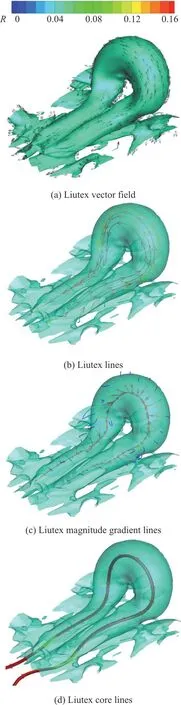
Fig.2 (Color online) R=0.05 iso-surface of hairpin vortex in a turbulent boundary layer shown
3.Discussion on vortex structures in MVG wake
3.1 Liutex identification
Figure 3 shows the vortex structures in MVG wake identified by Liutex magnitude iso-surface,where Fig.3(a) gives the iso-surface ofR=0.6, and three characteristic vortices marked by A, B and C are highlighted in Fig.3(b) and discussed in details.In Fig.3(b), the vortices A, B and C are extracted from the wake downstream which are spanwise-, wall-normaland streamwise-dominant vortex structures respectively with relatively stronger rotation strength than those in upstream.According to the mentioned above,the vortex core line, which can be obtained by combining the Liutex lines and the Liutex magnitude gradient lines, is an extrema and exclusive Liutex line to represent the Liutex tube (vortex) filled with Liutex lines.Hence, the Liutex core line should be the most appropriate approach with full information of a fluid rotation motion, compared with Liutex vector field,Liutex magnitude iso-surfaces or Liutex lines and other vortex identification methods.It is always difficult to determine an optimal threshold for the vortex identification based on iso-surface, since vortex tubes are featured by the non-uniformly distributed rotational strength without a specific characteristic value.The comparison ofR=0.6 andR=3 iso-surfaces in Fig.3 shows that the visualization effect is altered by the selection of threshold.To verify the practicability and accuracy of Liutex core line identification method on our case, both distributions of the vortex core line and the 2-D surface streamlines of the vortices A, B and C are shown in Fig.4.In Fig.4(a), the streamlines exhibit a spiral pattern around the Liutex core line on the cross-section of the vortex A, and a similar phenomenon can be found from Figs.4(b), 4(c).This indicates that the Liutex core line method is straightforward, robust and efficient for accurately extracting the rotation axis of a vortex structure without any user-specified threshold.
Besides the accurate vortex identification, the interaction between these identified vortex structures including the streamwise vortices and the K-H vortices (vortex rings with both spanwise and wall-normal characteristics) is also carried out based on the Liutex vector in the following.An intuitive view on the rotation strength of vortex structures behind the trailing edge of MVG can be derived by plotting the instantaneous contour distribution of Liutex magnitude in Fig.5.It can be observed that the rotation motion is weakened and diffused when traveling downstream.However, some rules or patterns can be found from the quantitative analysis.The Liutex vector is decomposed along the spanwise(x), wall-normal (y)and streamwise (z)directions.Integrals of Liutex components are employed to track the evolution of the strength of the vortical structures.The Liutex integrals over the crossflow plane are respectively defined as:
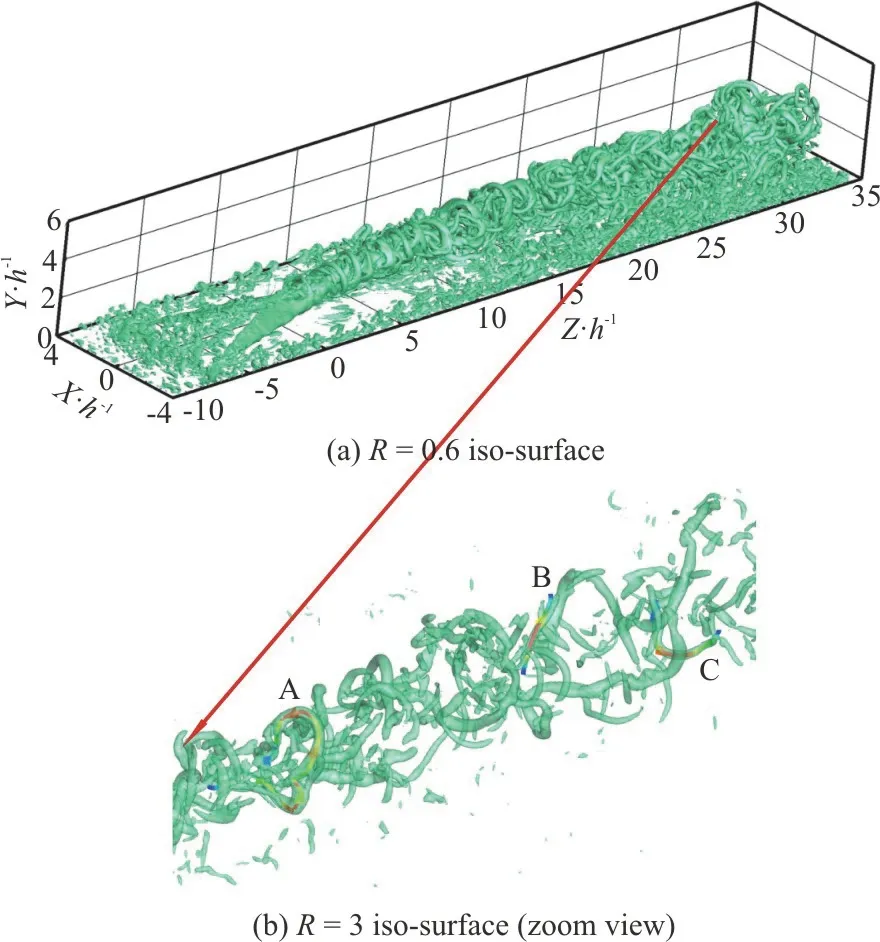
Fig.3 (Color online) Vortex structures in MVG wake identified by Liutex magnitude iso-surface
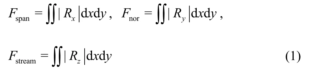

Fig.4(Color online)Three vortices A,B and C identified by surface streamlines and the vortex core line

Fig.5 (Color online) Liutex magnitude contour distribution inthe central plane of MVG wake flow
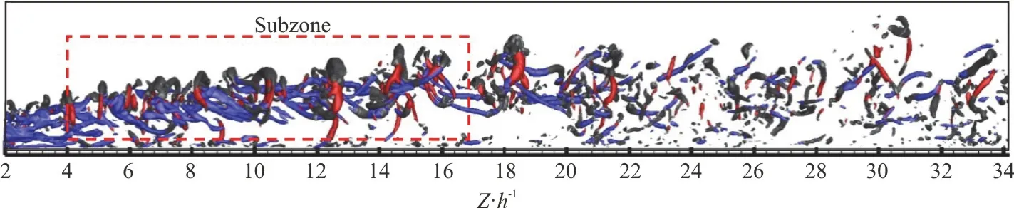
Fig.6(a) (Color online) Instantaneous Liutex integral distributions along the streamwise direction
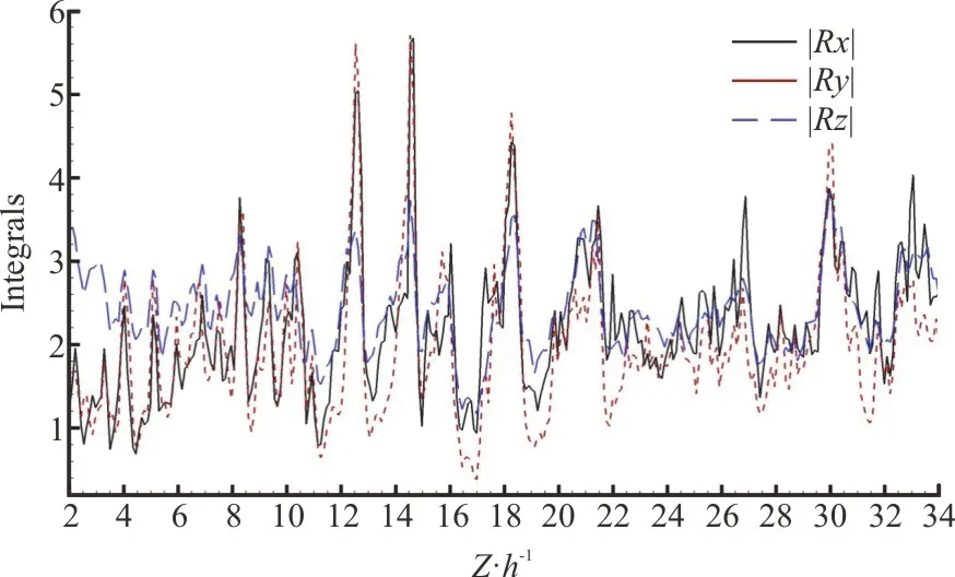
Fig.6(b) (Color online) The corresponding wake flow by isosurface of Liutex components
whereFspanis the surface integration of spanwise Liutex magnitude over eachxoyplane, andFnorandFstreamare the surface integrals of wall-normal and streamwise Liutex magnitude, respectively.The absolute value of each Liutex component is considered since only the magnitude of the Liutex integral is of interest.The K-H vortex can be detected by the peaks ofFspanorFnor.The distributions of the three Liutex integrals over the cross-flow plane alongzdirection from one snapshot are displayed in Fig.6, and the iso-surfaces of the instantaneous Liutex components are shown in the top figure to clarify the relation between the Liutex integrals and the spatial organization of the flow.The iso-surface of Liutex components indicates a train of arc-shaped vortices grow, and quickly break down into a series of smaller vortices, and continue to travel downstream and eventually dissipate due to viscosity.In the upstream region of the MVG wake flow in Fig.6, the streamwise vortex performs a regular development to downstream andFstreamtakes a much higher magnitude value thanFspanandFnordue to the initial period of the vortex generation (beforex/h=4).However,FspanorFnor, which is associated with the vortex shedding of K-H vortices, exhibiting much stronger fluctuations and larger magnitudes of integrals thanFstreamwhile developing along the streamwise direction.The peaks ofFspanandFnorappear atx/h=12.5,x/h=14.5andx/h=18.0.It indicates that the trailing edge of MVG can be placed at the location of around 15hfrom the baseline of the controlled area (separation bubble or shock root, etc.),for the optimization study of MVG design.Meanwhile,a subzone in Fig.6 which is characterized by the spanwise- and wall-normal-dominant vortical structures can be considered as the effective control section, since the K-H vortex structures with both wall-normal and spanwise characteristics can maintain much longer and are more capable to drive the rotation motion in the process of developing downstream during this section.Moreover, the wake in far downstream is not considered due to a serious dissipation of vortices as well as the wall turbulence effects during this process.
3.2 POD for multi-scale coherent structures
In section 3.1, it is proved that the information for each vortex can be described by the Liutex core line with the Liutex magnitude, and the evolution of the MVG wake flow field can be statistically tracked by the Liutex vector.To further investigate the principal components of multi-scale/frequency vortical structures of MVG wake, POD is applied over 200 snapshots of the flow field around MVG in this study, and both velocity vector and Liutex vector are selected as the input data.Additionally, the Liutex core line method is utilized to analyze the features of each POD mode.
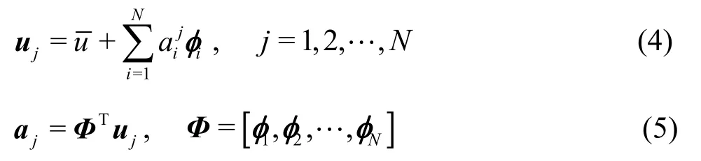
In the case that the number of spatial grid points(2.8×10⁷) is much larger than the number of time steps(200) in our case, the snapshot POD method proposed by Sirovich[47]is used due to the limited memory.The goal of POD is to obtain a proper orthonormal basisfrom a real-valuedM×NmatrixU=(u1,u2,… ,uN) of rankr≤min {M,N}with columnsuj∈RM, 1≤j≤NandNdenotes the number of the snapshots.As a conventional input, the matrixUconsists of the velocity componentsu=(u,v,w)T, whereu,vandware velocity components inx,yandzdirections.The covariance matrix of velocityR=UTUhas the following expression:

whereλiandAiare the eigenvalues and corresponding eigenvectors of auto-covariance matrixR.The rank of the eigenvalues in descending order isλ1≥λ2≥ … ≥λN>0.Then the characteristic functionφican be obtained by projecting the matrixUonto each eigenvectorAi, and the normalized form which is called POD mode can be written as

whereairepresents the time coefficient of each POD modeφi.The total energy of the flow can be obtained from the sum of all eigenvalues.The sizerof the reduced dimension of the matrix can be determined by the relative energy in terms of the firstrPOD basis vectors according to the following formula

The MVG wake flow field is identified by the iso-surface ofR=0.6 is shown in Fig.7.The subzone squared by red dotted lines in the figure is selected for the following POD analysis to reduce the computation complexity, due to multiple scales and more regular structures in this subzone.The parameters of the subzone are given in Table 2.

Table 2 Parameters of subzone
The snapshotujis defined as follows
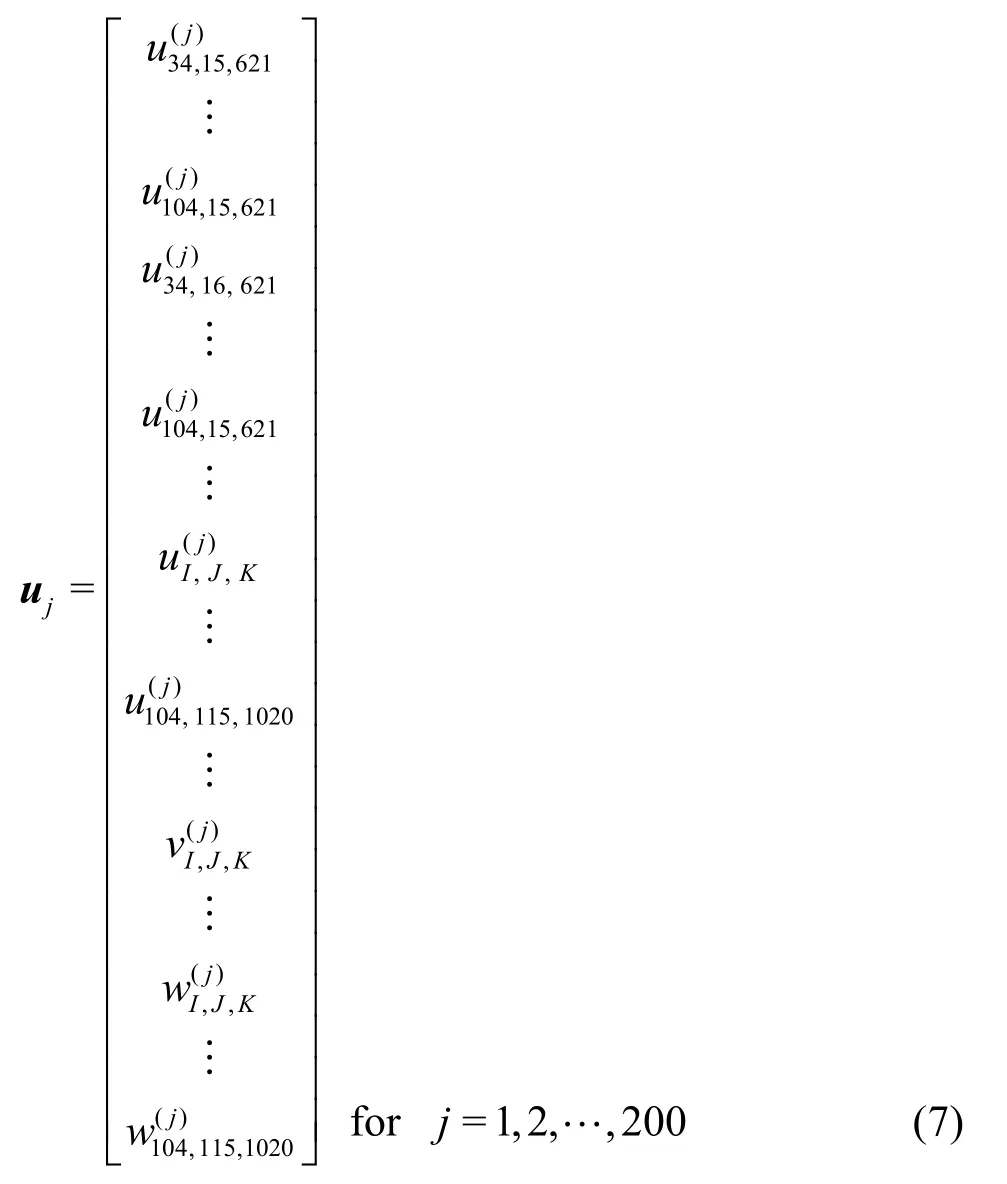
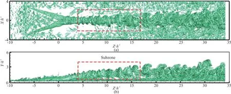
Fig.7 (Color online) MVG wake flow field identified by R=0.6 iso-surface
whereu(j),v(j)andw(j)are velocity components att=(188+0.5j)T.Thus, the dimension of the original flow field matrixU=(u1,u2,…,u200) should be 8605200×200.To determine a proper number of firstrmodes to reconstruct the snapshot, the accumulation energyε(i) fori=1,2,… ,200 as well as the eigenvaluesλiof the covariance matrixRin descending order except for the mean mode (mode 0) are shown in Fig.8.By the distribution ofε(i) which represents the energy proportion of the firstimodes, the first 45 modes contain more than 80% of the total energy,hinting that there is a wide range of characteristic energy containing multi-scales contributing to the velocity fluctuations in the MVG wake flow.In addition, an intuitive comparison between the original data and the reconstructed data with the first 45 POD modes is given in Fig.9.Figure 9(a) shows the vortical structures att=188.5Tbased on the original data while Fig.9(b) shows the vortical structures based on the reconstructed data with the deterministic part of the flow field being separated from the random part.From the comparison, the first 45 POD modes successfully reconstruct the flow field without losing the main fluid structures.
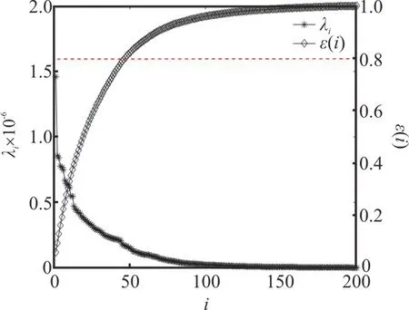
Fig.8 (Color online) Eigenvalues of the covariance matrix and the accumulation energy for 200 POD modes
Prior to demonstrating the significant contributions of the low-order POD eigenmodes to the combined modal kinetic energy, the spatial organization of the first few characteristic modes is presented based on Liutex identification.Figure 10 shows four characteristic POD modes in descending order respectively identified by Liutex magnitude iso-surface (left) as well as the Liutex core line (right).The mean mode which is contributed by the time-averaged velocity flowfield is given as mode 0 in Fig.10(a).In the figure, a pair of primary counter-rotating streamwise vortices with the largest scales is observed by the iso-surface ofR=4 and an asymmetry of these two “legs” hints a remarkable 3-D coherent characteristics of the average flowfield.Meanwhile, another pair of counter-rotating streamwise vortices, which performs a rather weak rotation strength (Liutex magnitude is smaller) and an opposite rotation axis direction compared to the primary one, is found under the primary pair based on the Liutex core line identification (right figure).This pair of weak vortices has been discovered in many experimental researches for the mean flow and confirmed to be the secondary vortex induced by the interaction between the primary vortex pair and the wall.
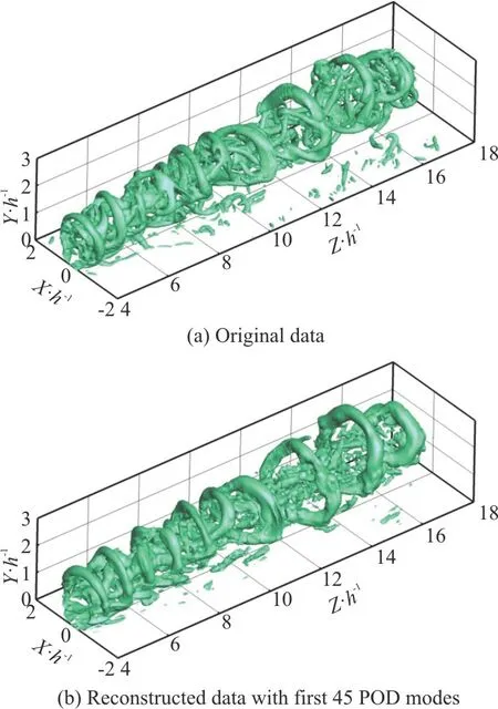
Fig.9 (Color online) Vortex structures of the subzone identified by iso-surface of R=1
As a low-order POD eigenmode, mode 1 in Fig.10(b) accounts for 6% of the total kinetic energy.It can be observed fromR=2 iso-surface in the left figure of Fig.10(b), that mode 1 has some similarity to the mean mode due to the streamwise-oriented vortical structure distribution, and this means that the streamwise component of the MVG wake is dominant in terms of kinetic energy contribution.It is reasonable that the mode with large-scale structures contributes the majority to the total energy.However,different from the mean mode, according to the Liutex core line and the Liutex magnitude distribution, the vortical structure of mode 1 has a behavior developing downstream along with a normal divergence (lifting or descending) of streamwise vortices and thus becomes distorted and less organized.Therefore, Mode 1is featured by a fluctuated roll-up motion of streamwise vortex structures.
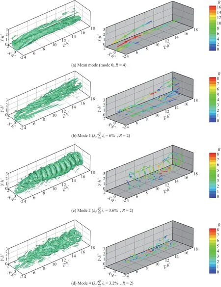
Fig.10 (Color online) Vortical structures of characteristic POD modes in MVG wake identified by Liutex magnitude iso-surfaces(left) and by Liutex core lines (right)
On the contrary, the most significant unsteady feature of the MVG wake structures is revealed by mode 2 which accounts for 3.6% of the total kinetic energy in Fig.10(c).It should be noted that modes 2,3 are pairing which supports the same vortex characteristics and thus only mode 2 is discussed here.Based on Liutex core line distribution, mode 2 presents rather organized arc-shaped vortices(unclosed vortex rings) shedding with a relatively high frequency and is featured by high fluctuation as well as high Liutex magnitude of spanwise- and normal-oriented vortical structures induced by the K-H instability.Additionally, another unsteady feature is reached by the appearance of upright vortices in the wake, connecting the primary wake trajectory and the wall vortices.It can be seen from the bottom Liutex core line with much lower Liutex magnitude that the upright vortices are roughly aligned with the wall-normal direction, and periodically shed away from the upstream.
Mode 4 with relatively unsteady features is depicted in Fig.10(d).It seems difficult to obtain the new findings from Liutex magnitude iso-surface ofR=2 in the left figure, but, however, a significant amount of streamwise-spanwise-oriented flow patterns are found to be contained in the small-scale structures according to the Liutex core line distribution in the right figure, although they are convoluted.These streamwise-spanwise-oriented vortices are subject to low-frequency oscillations of the wall vortices, and the details will be discussed in the following.In fact, as the POD mode goes to a higher order, the vortical scale becomes smaller, and the structures become more fluctuated and incoherent,thus, the remaining high-order POD modes are not shown here.
Besides the discussion of the spatial features for each mode, the temporal behavior of the characteristic POD modes associated with the multi-scale structures are also revealed, and the POD coefficients and their power spectra are respectively depicted in Figs.11, 12.In Fig.11(a), the time coefficients of the mean mode(mode 0) show extremely small amplitude without any periodic characteristics, and thus demonstrate their contributions to the steady part of the instantaneous flowfield.Althougha(t) of mode 1 is non-periodic,it shows unsteady temporal characteristics.The coefficientsa(t) of modes 2, 3 in Fig.11(b) display extreme fluctuated and periodic curves along with the number of snapshots of the flowfieldN, and match the behavior of the vortex ring shedding.Meanwhile,the peak Strouhal number,St=0.072, is the dominant high frequency of K-H vortices in MVG wake (Fig.12), whereSt=fh/U∞.In addition,according to the power spectra of mode 2 in Fig.12,another peak frequency with much lower power(amplitude) can be observed and it indicates the appearance of upright vortices connecting the primary wake trajectory and the wall vortices.Mode 4 takes a relatively lower frequency (St=0.044) due to low-frequency oscillations of the wall vortices.
4.Conclusions
In this study, a line-type vortex identification method named Liutex core line method, combined with the snapshot POD (proper orthogonal decomposition) is firstly utilized to analyze and assess the physical significance of each POD mode of a supersonic MVG (micro-vortex generator) wake flow with multi-scale vortical structures.Some conclusions are obtained and expressed as follows:
(1) The Liutex core line identification is successfully applied in our supersonic MVG wake flow case and verified to be an appropriate approach that provides full information of a fluid rotation motion,compared with other scalar-based vortex identification methods, that is threshold-free.

Fig.11 (Color online) Time coefficients of the characteristic POD modes
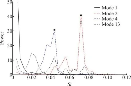
Fig.12 (Color online) Power spectra of the time coefficients of POD modes
(2) The integration of Liutex components are employed to track the evolution of the vortical structures quantitatively and statistically in MVG wake.The streamwise vortex detected byFstreamperforms a regular development to downstream during the initial period of the vortex generation but rapidly decays downstream, however, the K-H vortex exhibiting much stronger fluctuations and larger magnitudes ofFspanandFnorcan maintain much longer and are more capable to drive the rotation motion when developing downstream.Meanwhile, for the optimization study of MVG design, the effective control section of the MVG wake can be determined by peaks ofFspanandFnorthrough using Liutex integration.
(3) The physical mechanism of each POD mode for multi-scale and multi-frequency vortical structures in the MVG wake is investigated by the Liutex core line method.Two pairs of counter-rotating streamwise vortices are identified by two pairs of Liutex core lines from the mean mode (mode 0), which is contributed by the time-averaged velocity flowfield,and the primary pair can be accurately distinguished from the secondary pair by the Liutex magnitude on the Liutex core lines.Mode 1 is featured by a fluctuated roll-up motion of streamwise vortex with large-scale structures, and the streamwise component of the MVG wake is demonstrated to be dominant in terms of the total kinetic energy contribution.Mode 2(mode 3) reveals the most significant unsteady feature of the MVG wake which presents the organized arc-shaped vortex shedding induced by the K-H instability with a dominant shedding frequency ofSt=0.072.Additionally, another unsteady feature contributes to the appearance of upright vortices connecting the primary wake trajectory and the wall vortices and periodically shedding away from the upstream.Mode 4 is featured by streamwisespanwise-oriented vortices which subject to lowfrequency oscillations of the wall vortices, and thus takes a relatively lower frequency ofSt=0.044.
Acknowledgments
This work was supported by the National Natural Science Foundation of China (Grant No.51906154).The computation is performed by using MPI code“LESUTA” which was developed by Drs.Qin Li and Chaoqun Liu.
杂志排行

水动力学研究与进展 B辑的其它文章
- Prediction of the precessing vortex core in the Francis-99 draft tube under off-design conditions by using Liutex/Rortex method *
- Experimental study of an ellipsoidal particle in tube Poiseuille flow *
- The hydraulic performance of twin-screw pump *
- Numerical investigation of frictional drag reduction with an air layer concept on the hull of a ship *
- Effects of finite water depth and lateral confinement on ships wakes and resistance *
- Large eddy simulation of turbulent channel flows over rough walls with stochastic roughness height distributions *