Experimental study of an ellipsoidal particle in tube Poiseuille flow *
2020-12-02YuanfengCuiXiangtingChangHaiboHuang
Yuan-feng Cui, Xiang-ting Chang, Hai-bo Huang
Department of Modern Mechanics, University of Science and Technology of China, Hefei 230026, China
Abstract: Behaviors of a prolate ellipsoid inside circular tube Poiseuille flow are studied experimentally.In the study, Reynolds number Re∈ (100,700) and the confinement ratio D/ A ∈ (1.2,2.8) are considered, where D is the diameter of the tube and A is the length of the major axis of the ellipsoid.Two typical stable motion modes are identified, namely, the horizontal, and inclined modes.Then another inclined mode (inclined mode II) is found at high Reynolds number (R e∈ (1000,3200)) and small D/ A, and the inclined angle of ellipsoid increases with the increase of Re.The possible mechanism is explained.Our experiment shows that the lagging velocity U increases as Re increases.Further numerical analysis using FLUENT shows that due to the increase of U, the moment acting on the particle would make the inclined angle of the particle increase.
Key words: Ellipsoidal particle, Poiseuille flow, circular tube, experiment
Introduction
The motion of particles in tube flows is ubiquitous in nature.The research about this area has many applications in industries, such as chemical,biological, and mechanical engineering.Many studies on the motion of particles in simple flows have been carried out, such as particles’ rotational behaviors in Couette flow[1-7]and sedimentation of particles inside tubes[8-10].
The motions of spherical particles have been studied extensively.Segre and Silberberg studied the migration of neutrally buoyant spheres inside Poiseuille flow[11].They found that spherical particles migrate towards an equilibrium position and equilibrate at a distance of 0.6 times the radius of the tube from the tube’s center[11].That is referred to as Segre Silberberg effect.The migration of dilute suspensions of particles in Poiseuille flow with 600<Re<1700 has been investigated by Matas et al.[12].The tubular pinch effect has been found,namely that particles accumulate on a narrow annulus and move toward the wall asReincreases.Li and Xuan[13]studied the cross-stream migration of spherical particles in a combined pressure- and electric field-driven flow of viscoelastic fluid through a straight rectangular microchannel.They found that particles migrate toward the centerline of the channel if they are leading the hydrodynamic flow due to positive electrophoresis.Conversely, lagging particles due to negative electrophoresis migrate toward the walls of the channel.
For the behaviors of a non-spherical particle in tubes, Jeffery investigated the rotation of an ellipsoid in a Couette flow under Stokes flow condition[4].The theoretical equivalent viscosity coefficient of the particle suspension was obtained.Karnis et al.[14]studied the migration of non-spherical particles in Couette and Poiseuille flows and the inertial effect on particles’ motion was discussed.They observed that for a rod-like particle, the major axis of the particle rotates on the plane passing though the center of the particle and the tube axis (tumbling state), while for a disk-like particle, it rotates with its minor axis perpendicular to that plane (log-rolling state).Byeon et al.[15]also have shown that a prolate ellipsoid may adopt the tumbling state in the Poiseuille flow in their experiments.Recently, du Roure et al.[16]reviewed the advances in experimental studies on fibers’ motion in a narrow channel, the fiber motion modes were discussed.
With the rapid development of computer technology, some numerical simulations have been carried out to study the behaviors of spherical particles[17-18]and non-spherical particles in a tube[19-22].For nonspherical particles, Feng and Joseph simulated the motion of an ellipse in 2-D creeping flows using a finite element (FE) method[19].It was found that a neutrally buoyant particle exhibits the Segre Silberberg effect in a Poiseuille flow.The driving forces of the migration have been identified as a wall repulsion due to lubrication, an inertial lift related to shear slip, a lift due to particle rotation and the velocity profile curvature.Pan et al.[21]simulated the motion of a neutrally buoyant ellipsoid in tube Poiseuille flow and investigated its rotation and migration be havior inside circular tubes.They found its rotation exhibits distinctive states depending on the range ofReand the shape of particle.Later, Huang and Lu[20]studied ellipsoidal particle inside tube Poiseuille flow with Reynolds number up to 360 using a lattice Boltzmann method (LBM).The effects of tube diameter (D), inertia of the particle and the flow,and the particle geometry (both prolate and oblate ellipsoids) were considered.It was found that which mode occurs depends on the competition between fluid and particle inertia.When the fluid inertia is dominant, the log-rolling mode appears, otherwise, the kayaking mode appears.Başağaoğlu et al.[22]simulated settling trajectories of discretized individual or a mixture of particles of different geometrical shapes in a quiescent fluid and their flow trajectories in a flowing fluid using LBM.Significant effects of particle shapes on the settling or flow trajectories were demonstrated.
For the motion of particles especially ellipsoidal particles in tube, although many numerical simulations have been carried out, there are few experimental studies.Besides, the numerical results mentioned above have not been confirmed by experiments.In the present experimental study, the motions of a prolate ellipsoid witha:b=2inside circular tube Poiseuille flows were investigated using particle image velocimetry (PIV), whereaandbare the semi-major axis and semi-minor axis of the ellipsoid, respectively.The confinement ratio of the diameter of the tube and the major axis of the ellipsoid isD/A∈ (1.2,2.8), whereA=2a, and theReis in the range of (100,700).Three typical stable motion modes are identified and discussed.
1.Experimental methods
1.1 Experimental apparatus
Figure 1 illustrates a schematic diagram of the experimental setup.If not specified, the inner diameter and outer diameter of the circular glass tube are 36 mm and 44 mm, respectively.The length of the circular tube is 1 400 mm.A rectangular glass chamber surrounded the tube and the space between the chamber and the tube was filled with the suspending fluid (see Fig.1).In this way, the optical distortion due to the curvature of the water inside the circular tube was diminished[23].The circular tube was oriented vertically.The bottom of the circular tube was connected to the syringe pump through a flexible silicone tube, and the syringe pump was immersed in a basin filled with water.When the pump worked,Poiseuille flow was formed upward in the circular glass tube.The fluid flows to the basin through another flexible silicone tube connecting to the upper part of the tube.Hence it is a circulation system.When the transient velocity field in a plane passing through the tube axis of the circular tube needed to be measured and visualized, a 2-D PIV system was used(see Fig.1).A semiconductor laser (SMSEMI-8W,wavelength 532 nm) was used as an illuminating light source.Tracer particles (mainly SiO2) added into the fluid fluoresced because of the laser irradiation.A CCD camera (SM-CCDB5M16, Nikon 24 mm/F2.8)was placed perpendicular to the plane illuminated by the laser to record velocity field information.Both camera and laser were connected to the synchronous controller (SM-MicroPulse725).The following method was used to ensure the laser sheet passes through the axis of the tube.The orientation of the laser was adjusted until there is only one beam on the back wall after it passing through the tube perpendicularly to the glass wall.Otherwise, there are many beams due to the reflection and refraction of the curved glass walls.

Fig.1 (Color online) Schematic diagram of experimental apparatus
To record the behaviors of particles, the semiconductor laser was replaced by another same CCD camera.The directions of the two cameras are perpendicular to each other so as to capture the motion details of the particle in the tube.The two cameras were also fixed at the same height by tripods.The synchronous controller was used to control the cameras to take photos simultaneously.Ellipsoidal particles with different size but identical aspect ratioa:b:c=2:1:1 were used in present study, wherea,bandcare the lengths of the three semi-principal axes of the particles (see Fig.2).The polylactic acid(PLA) was used to manufacture the particles using a 3-D printing technology.The density of all particles is 1.02×10³kg/m3, which is close to the density of water.Appropriate amount of sodium chloride was added to the water so that the particles could suspend in the sodium chloride solution, thus eliminating sedimentation effect.Hence, the density of fluid is 1.02×10³kg/m3.After the flow became steady, the particle was released from the bottom of the circular glass tube.
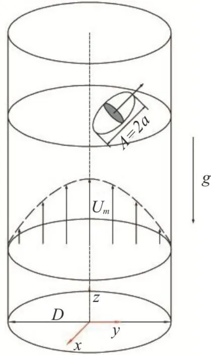
Fig.2 (Color online) Schematic diagram for the motion of a prolate ellipsoid in a circular tube Poiseuille flow.The density of the fluid is the same as that of the particle so that the sedimentation effect was eliminated
1.2 Experimental procedure
For each experiment, after turning on the syringe pump, first we have to wait for several minutes to ensure a steady Poiseuille flow forms in the tube.So,100 pictures of transient velocity field in an axisymmetric plane of the circular tube was measured using the PIV system.Second, a particle was released.The particle was initially fixed at the center of the tube bottom before the experiment started, and its long axis coincides with the tube axis.Third, when the particle moved upwards into the camera’s field of view driven by the Poiseuille flow, imaging system was turned on to record the movement of the particle.All experiments were conducted at room temperature.
2.Validation experiment
The movement of the ellipsoid inside circular tube Poiseuille flow is illustrated in Fig.2, whereD=2Rdenotes the diameter of the circular tube.In this study, the key non-dimensional parameters are:the non-dimensional width of the tubeD/A, and the Reynolds number (Re).Reis defined as

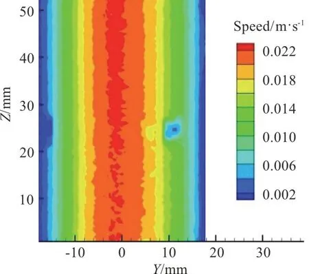
Fig.3 (Color online) Transient velocity field measured by the PIV system
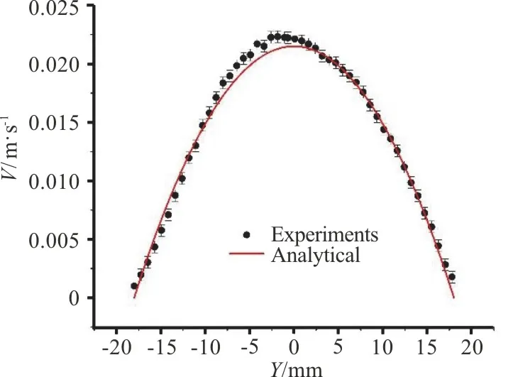
Fig.4 (Color online) Vertical velocity at Z=40 mm and the corresponding analytical result for the Poiseuille flow
whereUmis the maximum velocity of the Poiseuille flow without the particle and the kinematic viscosity of the fluid isν=1.007× 10⁻⁶m2/s.Without the particle, we checked the velocity field in the axisymmetric plane of the tube to see whether the Poiseuille flow is fully developed.Figure 3 is one of the 100 transient velocity fields measured by PIV, and other pictures are all similar to Fig.3.Figure 4 shows the velocity profile atZ=40 mm in Fig.3 and the corresponding analytical one for the Poiseuille flow.It is seen that the measured velocity profile is approximately parabolic and it is close to that of the analytical one.Hence, it is believed that the Poiseuille flow was fully developed in the tube.If not specified,the maximum velocity in the tube is 0.0079 m/s<Um<0.0229 m/s in our experiments.The maximummeasurement error of the maximum velocity is±0.0005 m/s.

Table 1 Comparison of equilibrium radial positions with previous result
Furthermore, several experiments about spherical particles were also performed to validate the present experimental method.In these experiments, spherical particles with different radii were released in the tube Poiseuille flow.It is observed that the particles migrated radially along the flow until they reached equilibrium radial positions, which is between the axis and the wall.That is consistent with the result in Ref.[14].The final equilibrium radial positions of the particles were measured and compared with the results in Ref.[14] (see Table 1), wheredis the diameter of the spherical particles andr*/Ris the normalized equilibrium radius.It is seen that present results agree well with those in Ref.[14] with maximum error about 6.2%.Hence, present experimental method is valid.
3.Results and discussions
3.1 Motion modes at <700 Re
A series of experiments with different Re and confinement ratio D/A were carried out and two steady motion modes are identified: the horizontal,and inclined modes.Figure 5 shows the phase diagram in the (D/A,Re) plane that we obtained.It is seen that the inclined mode mainly appears in two regions:one is at smallD/A, the other is at largeD/AwithRe≈ 150.The horizontal mode appears at moderateD/Aand relatively largeRe.
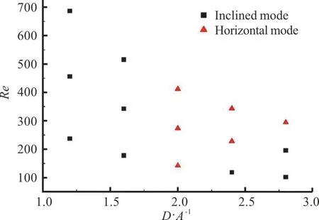
Fig.5 (Color online) Phase diagram of motion modes for a prolate ellipsoid inside tube Poiseuille flows.Each symbol represents an experiment our carried out
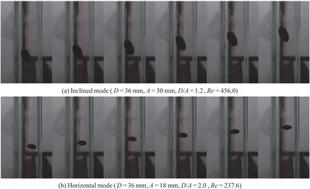
Fig.6 (Color online) Snapshots of motion modes for a prolate ellipsoid inside tube Poiseuille flows.Time intervals for successive frames in (a), and (b) are both 150 ms.The axes of the tubes are shown in red.
Figure 6 shows the snapshots of two modes.For the inclined mode, the ellipsoid moves off-axis with a constant inclined angle (see Fig.6(a)).The major axis of the particle is inside the plane passing the tube axis and the center of the particle.It is found that the inclined angleβis a function of Reynolds number(see Table 2).The maximum measurement error of the inclined angle is ±2°.From Table 2, we can see that whenReincreases, ifD/Ais small (e.g., 1.2), the inclined angle increases.However, ifD/Ais large(e.g., 2.8),βdecreases withReuntil it reaches zero.It is noticed that whenβ=0°,the motion mode is the horizontal mode (see Fig 5).For the horizontal mode, the major axis of the ellipsoid is always horizontal (see Fig 6(b)).Furthermore, the major axis of the ellipsoid is perpendicular to the plane passing through the tube axis and the center of the particle.
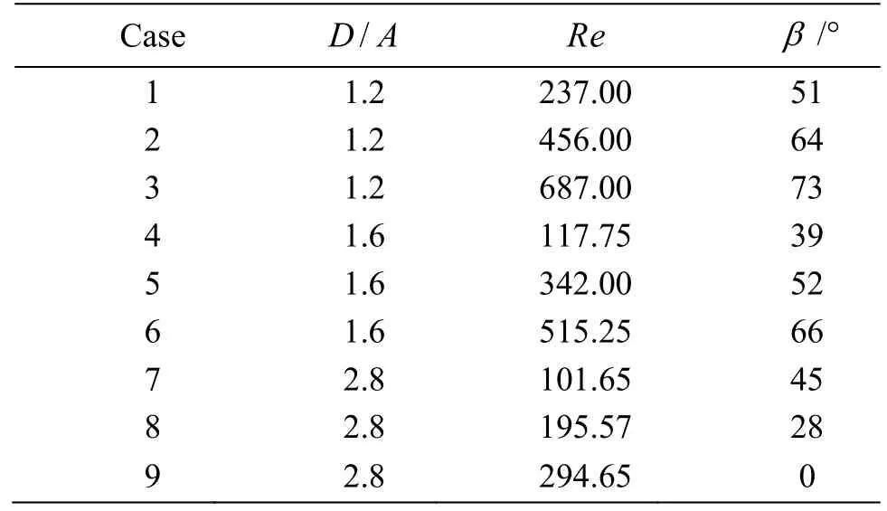
Table 2 The inclined angle β as a function of Re at different D/ A
The velocity fields for both modes were also measured.Snapshots of transient velocity fields are shown in Fig.7.For the inclined mode, the plane shown in Fig.7(a) approximately passes through the tube axis and the particle center.It is seen that the fluid velocity near pointPis larger than that near pointQ, wherePandQrepresent the two endpoints of ellipsoid’s major axis, respectively.It is seen that the velocity around the pointPis large.According to Bernoulli’s Law, the pressure here is slightly lower than that atQunder the circumstances of this relatively highRecase.Hence the ellipsoid would be inclined.For horizontal mode,the plane shown in Fig.7(b) is approximately perpendicular to the major axis of the particle.From Fig.7(b) we can see that the particle is close to the wall.Due to the shear stress acting on the particle, the particle may rotate clockwise.Then the particle would behave like a spherical particle in a Poiseuille flow with its equilibrium location between the tube axis and the wall (Segre Silberberg effect[11]).
3.2 Inclined mode II at Re>1000
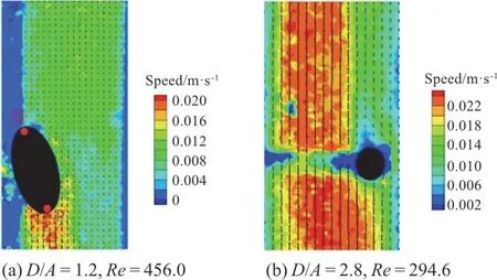
Fig.7 (Color online) Transient velocity fields of the inclined mode
In addition to the above two modes, another inclined mode was identified whenD/A=1.24 atRe>1000.The mode is referred to as inclined mode II.Snapshots of theparticle motion for inclined mode II are shown in Fig.8.It is seen that because the wall effect of the tube is significant, the centroid of the particle moves upward almost along the tube axis,which is different from the inclined mode in Fig.5.Figure 9 shows sinβas a function ofRe, whereβis the inclined angle of the particle.It is seen that sinβapproximately increases linearly withRe.To understand the mechanism why theβincreases withRe, two flow cases (cases A, B) were simulated using the commercial software Fluent.Firstly, Table 3 shows the velocity of the particleUp, the maximum value of streamwise velocityUmwithout particle,and corresponding velocity difference (lagging velocity)U=Um-Upin five cases with differentRe.It is seen that whenReincreases, the lagging velocityUincreases in the inertial frame moving withUp.In the simulations, both cases A, B were performed in the inertial frame, in which the particle is kept stationary while the wall move with velocity-Up.The force and moment acting on the particle are calculated through Fluent.In case A, the inclined angle of the particleβwas set to be 33°, corresponding to the experimental inclined angle of caseRe=1672 in Table 3.The velocity of moving wall-Up=0.06.The mass flow rate was specified at the entrance of the tube and it was calculated according toUpandUm.In case B,βwas also set to be 33°but the velocity of moving wall and mass flow rate in the inlet of tube were set to those in the case ofRe=2186in Table 3.The streamwise velocity field in the tube near the particle for cases A, B is shown in Figs.10(a), 10(b), respectively.All forces and moments acting on the particle for case A are close to zero, e.g., they-moment is -7.59×10⁻⁶N·m.Hence for case A, the particle is approximately able to keep stationary.However, for case B because the lagging velocityUincreases, they-moment is -1.31×10⁻⁵N·m.The magnitude is significantly larger than that in case A.So, we can imagine that the particle would turn clockwise in thex-zplane, which results in the increase of the inclined angleβ.Finally the particle in case B may reach another equilibrium angle with a largerβ.

Fig.8 (Color online) Snapshots of inclined mode II for a prolate ellipsoid inside tube Poiseuille flow ( D=16mm ,A=12.86mm ,D/ A=1.24at Re >1000).The tube axes are shown in red
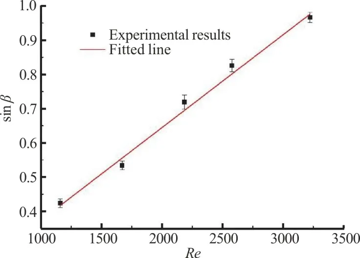
Fig.9 (Color online) sinβ as a function of Re with D/ A=1.24 and Re >1000 in the inclined mode II, where β is the inclined angle of the major axis of the particle
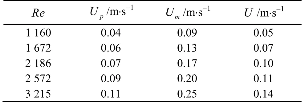
Table 3 Velocity of the particle Up, maximum streamwise velocity Um without particle, and corresponding velocity difference U for different Re

Fig.10 (Color online) Velocity field in the tube axis direction around the particle in the inertial frame moving with the particle.The inclined angle of the particle is β=33°.The initial maximum velocity
4.Conclusions
The behaviors of a prolate ellipsoid inside a circular tube Poiseuille flow were studied experimentally.First, the measured velocity profile in the circular tube was observed to be consistent with the corresponding analytical result.It confirms that the Poiseuille flow is fully developed.The lateral migration of a spherical particle in the Poiseuille flow was studied.The obtained equilibrium lateral positions agree well with those in the literature.Hence, the experimental algorithm is validated.
Next, we investigated the motion of an ellipsoidal particle witha:b:c=2:1:1inside a Poiseuille flow.The confinement ratioD/A∈(1.2,2.8) were considered with 100<Re<700.Two typical stable motion modes (the horizontal, and inclined modes) were identified and the phase diagram was obtained.The details of both modes were analyzed.For the inclined mode, asReincreases,whenD/Ais small, the inclined angle of the particleβbecomes larger and whenD/Ais large,βbecomes smaller.For the horizontal mode, the Segre Silberberg effect is also in effect.Finally,inclined mode II was found whenD/Ais small andRe∈ (1000,3200), sinβapproximately increases linearly withRe.To explore the mechanism,numerical analysis using FLUENT was carried out.Our experiment has shown that the lagging velocityUincreases withRe.The simulation result shows that due to the increase ofU, due to the moment experienced by the particle,βtends to increase.Hence, the particle may reach another equilibrium state with a largerβ.Our result may shed some light in understanding of particle behaviors in complex flows.
杂志排行
水动力学研究与进展 B辑的其它文章
- Prediction of the precessing vortex core in the Francis-99 draft tube under off-design conditions by using Liutex/Rortex method *
- The hydraulic performance of twin-screw pump *
- Numerical investigation of frictional drag reduction with an air layer concept on the hull of a ship *
- Effects of finite water depth and lateral confinement on ships wakes and resistance *
- Large eddy simulation of turbulent channel flows over rough walls with stochastic roughness height distributions *
- The velocity patterns in rigid and mobile channels with vegetation patches *
