Effects of finite water depth and lateral confinement on ships wakes and resistance *
2020-12-02ClmentCaplierGermainRousseauxDamienCalluaudLaurentDavid
Clément Caplier, Germain Rousseaux, Damien Calluaud, Laurent David
Institut Pprime-CNRS, University of Poitiers, ISAE-ENSMA, Chasseneuil, France
Abstract: Wash waves produced by ships disintegrate river banks and coastal lines.This phenomenon of bank erosion is mainly due to the height of the waves.Various factors govern the formation of these waves and their amplitudes: the geometry of the water channel,the shape and the speed of the boat, etc..These factors play an important role on the wave generation, in addition on the resistance of the ship and so on its fuel consumption.Whether to study the impact of wash waves on the ship's environment or its resistance, the analysis of the generated wake is essential.Hence a fine characterization of the wave field is necessary.This study proposes a comparison of wakes generated by two generic ships based on a Wigley hull with block coefficients 0.67 and 0.89 respectively representative of maritime and fluvial ships.The wakes generated in deep water and confined water configurations have been measured for different Froude numbers by a non-intrusive optical stereo-correlation method, giving access to a detailed and complete definition of the generated wave fields.The resistance of the ship hulls has been measured in deep and confined water configurations with a hydrodynamic balance.The results permit one to study the influence of both hull and water channel geometries on the ship wake, on the amplitude of the far-field generated waves and on the near-field hydrodynamic response.Moreover, resistance curves are obtained for both configurations and highlight the effect of both hull and water channel geometries on the resistance coefficient of the ship.A comparison of the resistance curves with or without the ship trim is conducted and shows the influence of the trim on the resistance coefficient in the different ship speed regimes.
Key words: Ship wakes, wash waves, confined water, ship resistance
Introduction
Various factors govern the generation and the amplitude of wash waves: the bathymetry of the water channel, the geometry and the speed of the ship, the hull shape.
On the one hand, when a ship navigates in a waterway of finite water depth, the effects of confinement result in a change of the shape of the generated wave field[1-7].As the shallow water wake shape highly depends on both the water depth and the ship speed, the non-dimensional height-based Froude number(whereUis the ship speed,gthe gravity andhthe water depth in the waterway), allows to distinguish various regimes[3,8].ForFrh<0.60, there are no visible effects of finite water depth and the wave field is similar to the deep water V-shaped Kelvin wake[9].This wake is composed of transverse and divergent waves,respectively perpendicular and oblique with respect to the advancing line of the ship.These two wave systems superimpose on a cusp line which defines the envelop of the wake and forms the typical Kelvin angleα=19.47° with respect to the advancing line.That angle remains constant until a threshold ship speed from which it decreases[10-17].For 0.60<Frh<1.00 the wake is transcritical from an undulatory point of view, its angle increases with the ship speed, as well as the wavelength of the transverse waves.At the particular speed corresponding toFrh=1.00, i.e.,the wake is critical and the envelop of the wake consists in a perpendicular bow wave in front of the ship (α=90°).In addition,the transverse waves disappear and the wake is only composed of divergent waves.ForFrh>1.00 the wake is supercritical and the bow waves folds backwards to the ship with respect to the Froude number asα=as in(1/Frh).This behavior is reminiscent of the Mach cone in supersonic aerodynamics.On the other hand, important hydrodynamic effects appear around the ship, when the waterway is confined both vertically and laterally.It has been highlighted by Scott Russell[18], through his observations and experiments in narrow and shallow waterways during the nineteenth century.The Scottish engineer has pointed out the decreasing of the water level around the ship, whose impact on the river banks is important.Moreover, the ship is subject to squat and there is a risk of touching the ground.Nevertheless, the major effect highlighted by Scott Russell is the apparition of a bow wave in front of the ship, causing an increase of the ship resistance.The effects of both vertical and lateral confinement on the ship resistance are different[18-20].Indeed, for a given water depth, the effect of the lateral confinement consists in the apparition of a peak in the resistance for a ship speed, corresponding to a height-based Froude numberFrh=1.00.The smaller is the width of the water channel, the higher is the peak of resistance atFrh=1.00.For a given channel width, the decrease of the water depth results also in the apparition of a peak in the resistance curve, but for a different height-based Froude number.Moreover,the smaller is the water depth, the lower is the speed that corresponds to the peak of resistance.In the case of both lateral and vertical confinement, hydraulic effects appear and the resulting resistance curve highlights two critical height-based Froude numbers.The hydrodynamics theory established by Schijf[21]leads to the theoretical expressions given in Eqs.(1),(2) (they are based on the mass conservation and Bernoulli equations):

where the critical Froude numbers are given as a function of the blockage ratio of the waterwaym=As/Ac(whereAsis the immersed cross-section of the ship andActhe cross-section of the canal),which reflects the importance of both vertical and lateral confinement.These two height-based critical Froude numbersFrh1,Frh2are plotted against the blockage ratiomin Fig.1.An increase of the blockage ratio, i.e., a decrease of the water depth and/or a narrowing of the width of the waterway,leads to a widening of the hydraulic transcritical region where the confined water effects occur.
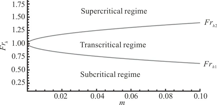
Fig.1 Schijf’s diagram.The curve representsthe theoretical values of the critical height-based Froud e numbers Frh1 and Frh2 given by Schijf’s theory[21]as a function of the blockage ratio m=As/Ac
Recent studies on the effects of the confinement of the waterway on ship wakes and the link with the ship resistance are built on numerical investigations[22-24].These numerical models are based on the resolution of Reynolds-averaged Navier-Stokes(RANS) equations, closed withk-ωSST ork-εturbulence models.The free-surface capturing strategy is based on a multi-phase approach using volume of fluid (VOF) method, and the ship motions are simulated by a dynamic mesh technique.However, the confinement has a strong impact on the energy repartition in the ship wake and on both hydraulic and undulatory components of the wake[25].These effects are still not completely described numerically or theoretically, and experimental studies on small-scale models are thus necessary to feed the analysis.
1.Experimental setup
1.1 Maritime and river ship hulls
The two ship hulls are based on a Wigley[26]hull with a rectangular section.This hull form is mathematically defined by the parabolic expression given in Eq.(3)
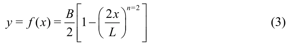
in whichxandyrepresent respectively the longitudinal and transversal axes of the ship.Lrepresents the length of the hull (L=1.2 m) andBits beam (B=0.18 m).During the experiments, the draft is (D=0.075 m).The maritime hull that has been analyzed is a classical Wigley hull noted WH2,where 2 remains the value of the exponentnin Eq.(3),of block coefficientCb=0.67.However,the block coefficients of river ships are around 0.8-0.9.Then another Wigley-based hull of block coefficientCb=0.89, noted WH8 and for whichn=8 in Eq.(3), has also been analyzed.This results in a heavier hull shape at the bow and the stern of the ship (Fig.2).
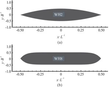
Fig.2 Comparison of the shape of the WH2 maritime hull and the WH8 river hull
1.2 The towing tank and the waterway
The wakes have been generated in the towing tank of the Institut Pprime.This canal is 20 m long and has a rectangular section of widthW=1.5 m.The water level can be set up to 1.2 m and a double bottom can be placed in the canal, to reduce the water level while maintaining the ship hull and the measurement tools fixed (Fig.3).A carriage tows the ship hull along the longitudinal axis of the canal at a speed up to 2.35 m/s.During the trial, the hull is kept fixed with a vertical mast so that roll, pitch and yaw motions are impossible.Finally, the canal is equipped with windows on its left-side, which allows sidevisualizations during the experiments.
The dimensional parameters for the deep water and confined water configurations have been established on the basis of two thresholds.First, a relation established by Zhu et al.[27]gives a threshold on the height-based Froude number, from which the finite water depth has an effect on the undulatory behavior of the generated waves.From observations on analytically calculated shallow water ship wakes,the authors have assumed that forFrh>0.58 the effects of finite water depth show up.Conversely, the water depth can be considered as infinite for height-based Froude numbers below this threshold.However, this threshold does not reflect the apparition of the hydrodynamic phenomena in the waterway.Thus, an empirical classification established by the International Towing Tank Conference[28]has been considered.This classification gives limit ratios between the geometric parameters of the waterway and the ship, which correspond to the apparition of the effects of the confinement of the waterway from a hydraulic point of view.These ratios areh/D=4 for the vertical confinementW/B=4, for the lateral confinement, andm=As/Ac=0.0625 for both.
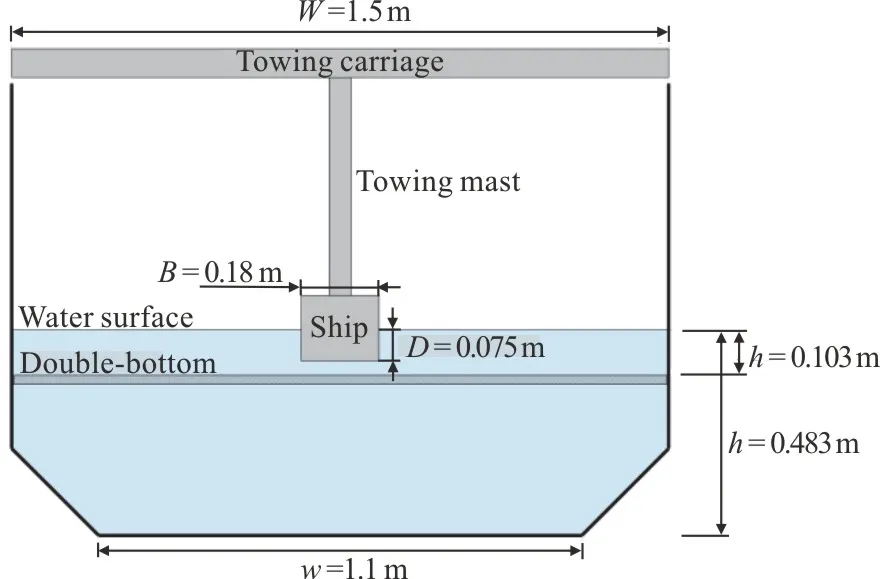
Fig.3 (Color online) Sketch of the transverse section of the towing tank and the ship hull.The towing tank has a trapezoidal transverse section in the deep water configuration(h=0.483 m).A double bottom is placed to elevate the bottom of the canal and convert the transverse section to a rectangular one in the confined water configuration(h=0.103 m)
Considering this, the wakes have been measured for two advancing speedsU=0.80 m/sandU=1.20 m/sand two water depthsh=0.483m(deep water configuration) andh=0.103m(confined water configuration).This set of parameters,summarized in Table 1, allows to cover a wide range of height-based Froude numbers, while staying under the limit length-based Froude numberFrL=0.50 from which the angle starts to decrease[10-17].In addition, the wide range of height-based Froude numbers allows to investigate subcritical, transcritical and supercritical wake shapes.As regards the hydraulic confinement, the width of the canal is the same for each configuration so the lateral confinement will be the same.However, the shallow water configuration is representative of the navigation in confined waters, as both undulatory (Frh>0.58)and hydraulic (h/D<4 andm<0.0625) confinement are taken into account.
Finally, the ship resistance has been measured in the deep water configuration for a range of length-based Froude numbersFrLbetween 0.13 and 0.63, corresponding to height-based Froude numbersFrhbetween 0.20 and 1.00.As regards the shallow water configuration, the range of length-based Froude numbers is almost the same (between 0.18 and 0.54).However, as the water depth is smaller, the height-based Froude numbers range from 0.60 to 1.85.Hence, this allows to investigate the behavior of the ship resistance around the height-based Froude numberFrh=1.00.In addition, the chosen ship speeds cover the theoretical values of the critical height-based Froude numbersFrh1andFrh2calculated by the hydraulic Schijf ’s theory[21].Figure 4 represents the values ofFrh1andFrh2against the blockage ratio of the water way, and both studied configurations are reminded.In the case of the deep water configuration, the critical height-based Froude numbers corresponding to the blockage ratiom=1/53.7=0.019areFrh1=0.83 andFrh2=1.17.For the confined water configuration, the blockage ratiom=1/11.4=0.088gives the theoretical valuesFrh1=0.65 andFrh2=1.37.
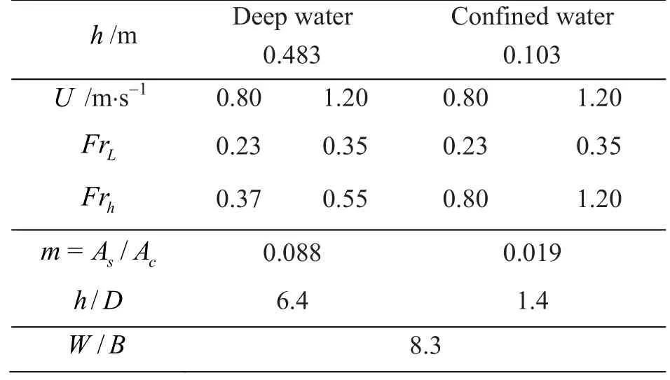
Table 1 Parameters of the experiments
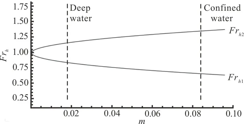
Fig.4 The curve represents the theoretical values of the critical height-based Froude numbers Frh1 and Frh2 given by the hydraulic Schijf ’s theory[21] as a function of the blockage ratio m.The dotted lines emphasize the deep and confined water configurations of the experiments
1.3 Measurement tools
1.3.1 The stereo-correlation method
The wakes have been measured with an optical measurement method based on a stereo-correlation principle[29].The method consists in recording the deformation of the free surface during the passage of the ship with two cameras.The latter ones (Jai RM-4200CL that deliver a resolution of 2 048×2 048 pixels and equipped with Nikkor AF 28 mm 1:2.8 lenses) are placed 1.5 m above the surface of water.They focus on the same zone with an opposite angle of ±15° with respect to the longitudinal axis of the canal, and ±35° with respect to the vertical axis.The common field covered by the cameras forms a rectangle of dimensions 0.75×0.90 m2, corresponding to the half width of the canal.The acquisition of the images is performed with a R&D Vision system,composed by the Hiris software piloted by a synchronization box EG.Then the cameras are synchronized with the start of the ship and the exposure time is set to 10 ms.The frequency of the acquisition of the images is set at 10 frames per second (fps).The first step of the stereo-correlation method consists in the calibration of the cameras.For that, a two-dimensional target of points is displaced in the air, along the longitudinal axis of the canal and the camera models are calculated with a dedicated algorithm.Then the canal can be filled up and the surface of water is sowed with floating perlite particles, of size between 1 mm-5 mm.These particles serve as markers that will follow the free surface deformations at the passage of the ship.Each run is performed three times to check the reproducibility of the measurement.Once the images have been recorded, a correlation algorithm based on the SLIP library[30]processes the image pairs.The free surface deformation is calculated at each time step with a spatial resolution of 10 mm and a precision of the water level of 0.1 mm.Finally, from the three wave fields calculated at each time step, a mean wave field is calculated.Then, the whole wake is reconstructed around the ship hull with a dedicated reconstruction program.The result is shown in Figs.5, 6, on which the black color represents the zones where the computing of the correlation is impossible because of either the absence of particles (chased away by the hull in the middle zone of the waterway), too high wave amplitudes on the banks or wave breaking.
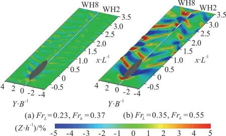
Fig.5 (Color online) Ship wakes measured in the deep water configuration.The right part of each wake corresponds to the maritime hull WH2 and the left one corresponds to the river hull WH8

Fig.6 (Color online) Ship wakes measured in the confined water configuration.The right part of each wake corresponds to the maritime hull WH2 and the left one corresponds to the river hull WH8
1.3.2 The multicomponent dynamometer and sidevisualizations camera
A multicomponent dynamometer Kistler 9272 is placed between the towing mast, which imposes the advancing speed, and the ship hull.It gives access to the three axial components of the force that opposes to the longitudinal motion of the hull, and the momentum around the vertical axis.As the hull is symmetrical and is aligned with the longitudinal axis of the canal, the transverse component of the force and the momentum around the vertical axis are negligible.Hence, only the longitudinal component of the ship resistance is considered for the calculation of the resistance coefficients.During the resistance trials,a high-speed camera has been placed on the side of the canal to access to a side-view of the wake generated by the ships, through the windows of the canal.A Photron Fastcam SA1.1 camera, which delivers a resolution of 1 024×1 024 pixels and equipped with a Sigma 28 mm F1.8 DG Aspherical Macro lens,performs the acquisition of the images at a frequency of 125 fps and is synchronized with the start of the ship.Then, the images are merged into one single image (Fig.8) with a dedicated C++ program based on the SLIP library[30].
2.Results
2.1 Ship wakes
The wakes measured in the deep water and confined water configurations are given in Figs.5, 6,on which the non-dimensional water depth is given as a percentage of the initial waterh=0.483morh=0.103m.The right part of each wake corresponds to the maritime hull WH2 and the left one corresponds to the river hull WH8.The wakes measured in the deep water configuration correspond to the classical Kelvin wake pattern, reflecting on the walls of the canal.Whatever the ship speed and its shape, the wake is composed of a transverse and a divergent wave system.A fast geometrical analysis leads to a value of the angle defining the envelop of the wake close to the Kelvin angleα=19.47°.There are no differences as regards the wavelengths of both wave systems,however, a small phase difference can be observed at the fastest ship speed (Fig.5(b)) between the wave systems generated by the two ship hulls.However, the higher block coefficient of the river hull generates a higher bow wave in both cases, and also non-linear components deforming the wake as well as higher wave amplitudes in the wave field.A focus on the walls of the canal, for a longitudinal positionX/Lbetween 0.5 and 2.0, highlights these differences.Indeed, for a length-based Froude numberFrL=0.23(Fig.5(a)), the maximum peak-to-trough amplitudes on the wall correspond to 4% of the initial water depth for the maritime hull WH2 and 10% for the river hull WH8.That represents an increase of 150% of the amplitudes of the wash waves reflecting on the walls.For the length-based Froude numberFrL=0.35(Fig.5(b)), the difference is less important as the peak-to-trough amplitudes are respectively of 11% and 15% of the initial water depth for the maritime and river hulls, representing an increase of 40% of the wave amplitude.In both cases, the waves generated by the river hull are more destructive.Finally, there are no visible effects of the vertical confinement, on both wake shape and angle, however the lateral confinement implies multiple wave reflections on the walls.Hence, the bow and stern wakes interact and superimpose, leading to the apparition of caustics in the wakes.
As regards the wakes generated in the confined water configuration (Fig.6), the effects of both lateral and vertical confinement are present.First, for the length-based Froude numberFrL=0.23, corresponding to a height-based Froude numberFrh=0.80,the wake is transcritical from a undulatory point of view: the transverse waves have disappeared and the wake is composed only of divergent waves.As regards the hydraulic confinement, two phenomena highlighted by Scott Russell[18]have appeared around the ships.The bow wave has straightened up and is perpendicular to the ship, and the lowering of the water level around the hulls extends up to the walls of the canal.In addition, there is a wave-breaking of the first transverse wave generated by the river hull WH2,which represents a risk for the river banks.For the length-based Froude numberFrL=0.35, corresponding to a height-based Froude numberFrh=1.20,the wake is supercritical.The wake is now composed only of divergent waves and the bow wave starts to fold backwards to the ship[3,8].This behavior is reminiscent of the Mach cone in supersonic aerodynamics.
2.2 Resistance curves
Figure 7 represents the resistance coefficientsCdof the ship hulls as a function of both length-based and height-based Froude numbersFrLandFrh(respectively the bottom and topx-axes),for the deep water configuration (a) and the confined water configuration (b).The dotted black lines correspond to the ship speeds for which the wakes have been measured, and the dashed black lines correspond to the theoretical values of the critical height-based Froude numbers given by Schijf's theory[21].The error bars represent the dimensionless measurement uncertainty of the resistance coefficient,derived from the measurement uncertainty of the drag force calculated with the GUM method[31-32].The resistance coefficientCdgives a non-dimensional vision of the ship resistance with the ship speed.It is calculated with the Eq.(4), in which formulaR(N)is the measured force,ρ=1000 kg/m3the density of the water in the canal andUthe ship speed.The quantityScorresponds to the wetted surface area of the ship, calculated with Eq.(5), in whichδ(x)defines the contour of the wetted cross-section of the ship hull[33].After calculation, the Eq.(6) is found,giving the relation between the wetted surface area and the geometric parameters of the hulls.In the case of the studied hulls,SWH2=0.324 m2andSWH8=0.372 m2.


Fig.7 (Color online) Resistance coefficients Cd of the ship hulls as a function of the length-based (bottom x-axis)and height-based(top x-axis) Froude numbers FrL and Frh.The dotted black lines remind the ship speeds for which the wakes have been measured with the stereo-correlati on method.The dashed black lines correspond to the theoretical values of the critical height-based Froude numbers Frh1 and Frh2
For the deep water configuration, there are oscillations in the resistance of the ship for length-based Froude numbersFrL<0.35, especially for the maritime hull WH2.These oscillations correspond to the interaction between the bow and stern waves whose wavelengths depend on the speed of the ship.So depending on the ship speed, the constructive or destructive interferences of these two wave systems will generate oscillations in the ship resistance.In addition, for a length-based Froude numberFrL>0.45, the resistance coefficient is constant and starts to decrease for a ship speed corresponding to a height-based Froude numberFrh>Frh1>0.83.Finally, the higher block coefficient of the river hull WH8 implies a higher resistance coefficient, as the displaced volume of water is more important.The resistance coefficients measured in the confined water configuration have a different behavior with the ship speed and are quantitatively higher than in deep water.The theoretical values of the critical height-based Froude numbersFrh1andFrh2given by Schijf's theory[21]correspond to drastic changes in the resistance coefficient value.First, there is a sharp increase of the resistance coefficient value for a height-based Froude numberFrh>Frh1>0.65.This sharp increase is followed by a plateau on which the resistance coefficient is constant and then the resis-tance coefficient decreases suddenly for a height-based Froude numberFrh>Frh2>1.37.The visualizations given in Fig.8 highlight the causes of the variations of the resistance coefficient.First, the sharp increase corresponds to the moment when the transverse waves are stuck at the stern of the ship.Then during the plateau, the bow wave appears and its amplitude slowly increases.The sudden decrease of the resistance coefficient corresponds to the moment when the ship passes over its own bow wave and rides it.

Fig.8 Side view of the wakes generated by the maritime hull WH2 in the confined water configuration during the resistance trials, for three different ship speeds (going right to left)
2.3 Influence of the trim on the ship resistance
Experiments have been carried out to identify the influence of the trim of the ship on its resistance coefficient in the different regimes.For that, the fixed-hull setup has been modified into a free-hull setup with the adaptation of a hinge system between the hull and the hydrodynamic balance, allowing it to trim.The ship resistance has been measured for the WH8 river hull in a shallow water configuration of trapezoidal cross-section with the following parameters:h=0.103m ,W=1.3m ,w=1.1m andD=0.04 m.These waterway parameters give a blockage ratiom=1/17.2=0.058corresponding to critical height-based Froude numbersFrh1=0.71 andFrh2=1.30.The resistance force measurements have been made with the fixed-hull system and the free-hull system and the results are given inFig.9, on which the error bars represent the dimensionless measurement uncertainty.
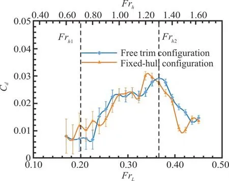
Fig.9 (Color online) Resistance coefficients Cd of the ship hull WH8 in confined water as a function of the lengthbased ( bottom x-axis) and height-based (top x- axis)Froude numbersFrL and Frh.The dashed black lines correspond to the theoretical values of the critical height-based Froude numbersFr h1and Frh2.The error bars represent the estimated measurement uncertainty of the resistance coefficient
These results show that the trim of the ship seems to have an influence in the transition between the suband transcritical regimes (i.e., around th e critical height-based Froude numberFrh1=0.71),although in the transcritical regime the resistance coefficient is the same with or without trim.In the supercritical regime the trim has a strong effect and shifts the peak of maximum resistance.The visualizations made during these experiments show that the stern sinkage increases with the ship speed and the apparition of the bow wave.The trim angle is maximum at the critical height-based Froude numberFrh2=1.30, where the resistance is at its maximum as well as the bow wave amplitude.The surfing of the bow wave still occurs above that ship speed, but the trim increases the wetted surface of the hull and so the ship resistance.
3.Conclusion
The wakes generated by hulls representative of maritime and river ships have been measured in a towing tank.The non-intrusive optical measurement method allowed to identify various wake shapes generated in deep water and confined water configurations, for different ship speeds.The results highlighted the effects of both ship and waterway geometries on the generated wakes.In the deep water configuration, the influence of the ship block coefficient on the amplitude of the wash waves has been characterized.In the confined water configuration, transcritical and supercritical wakes have been identified and compared.The effects of the vertical and lateral confinement on both undulatory and hydraulic components of the wakes have been studied.Their influence on the resistance of the ship has been emphasized during the resistance trials,combined with side-visualizations of the wakes.The influence of the trim of the ship hull on its resistance coefficient in the sub- and supercritical regimes has also been highlighted.However, in a real canal configuration, the current has a strong influence on these parameters.Hence, the measurement of both ship wakes and resistance in the presence of a co- and counter-current of river are necessary.This is our current line of research.
杂志排行

水动力学研究与进展 B辑的其它文章
- Prediction of the precessing vortex core in the Francis-99 draft tube under off-design conditions by using Liutex/Rortex method *
- Experimental study of an ellipsoidal particle in tube Poiseuille flow *
- The hydraulic performance of twin-screw pump *
- Numerical investigation of frictional drag reduction with an air layer concept on the hull of a ship *
- Large eddy simulation of turbulent channel flows over rough walls with stochastic roughness height distributions *
- The velocity patterns in rigid and mobile channels with vegetation patches *