Study on the flow structure around discontinued vertically layered vegetation in an open channel *
2020-12-02NaveedAnjumNorioTanaka
Naveed Anjum, Norio Tanaka,
1.Graduate School of Science and Engineering, Saitama University, Saitama-shi, Japan
2.International Institute for Resilient Society, Saitama University, Saitama-shi, Japan
Abstract: The flow structure and geomorphology of rivers are significantly affected by vegetation patterns.In the present study, the effect of vegetation in the form of discontinuous and vertically double layered patches particularly on the resulting flow turbulence was examined computationally in an open channel.A k- ε model was implemented in this research work which was developed using 3-D numerical code FLUENT (ANSYS).After the validation process of numerical model, the impact of discontinuous layered vegetation patches on the flow turbulence was investigated against varying vegetation density and patch length.The mean stream-wise velocities at specified positions showed larger spatial fluctuations directly upstream and downstream of vegetation elements, whereas sharp inflections in the profiles were witnessed at the top of smaller submerged elements i.e., z/ h s=1 (where z is the flow depth, hs is the smaller vegetation height).The reduction in flow velocity due to tall vegetation structure was more as compared with that of short vegetation.The mean velocity in the patch regions was visibly higher than that in the gap regions.The profiles of turbulent flow properties showed more rise and fall within the patches with a high vegetation density i.e., S s/d=4, S t/d=8 (where S s/d and S t/d are the smaller and taller vegetation spacing, while d is the vegetation diameter) as compared with low vegetation density i.e.,S s/d=8, S t/d=16.The turbulent flow structure in the large patch and gap regions was found to be more stable than that in the small patches and gaps; whereas, due to the variation in distribution form of the patch, turbulence is relatively unaffected, and the flow structure variation is low.Turbulence was observed to be large, followed by a saw-tooth distribution within the patches; whereas, low turbulence is observed in the non-vegetation regions.The turbulent intensity acquired maximum of 13% turbulence for dense vegetation arrangement as compared with that of sparse arrangement having maximum of 9% turbulent intensity.A noteworthy rise in turbulent kinetic energy and turbulent intensity was witnessed as the flow passed through the vegetated regions.Hence, a non-uniform flow was observed through discontinuous and double layered vegetation patches.
Key words: Discontinuous and layered vegetation patches, open channel flow, numerical simulation, mean flow velocity, turbulence modeling, flow characteristics
Introduction
Vegetation patches assume significant roles for ecological purposes and the physical surroundings of aquatic creatures[1].The growing forms of vegetation patches are stimulated by the flow.In addition, the patches of vegetation modify flow by inducing turbulence and disturbing flow properties[2].In hydraulics, vegetated flow has become a very important research area as it contributes its part with respect to both physical and biological point of view[3-4].
The two equation closure models established on Reynolds-averaged Navier-Stokes (RANS) models were suggested and replicated by many investigators[5-6].A 3-Dk-εturbulence model was proposed by Kamel et al.[7]for analyzing the turbulent flow properties in an open channel.Similarly, Choi and Kang[8]developed Reynolds stress models (RSM)for turbulence modeling of flows with vegetation.The turbulence characteristics through vegetated open channel flows have been numerically studied by Anjum et al.[9-10].Wang et al.[11]performed numerical investigation through double layered vegetation and found that both layers of vegetation offer resistance to the flow, however, the hindrance was large for higher vegetation as compared with the shorter vegetation.Thek-εmodel has been successfully applied to rigid vegetated open channel flows by many previous researchers[12-13].Aminian[14]performed numerical simulation to evaluate the turbulent flow behind a square cylinder, whereas, Chang et al.[15]conducted simulation to study the flow behind circular cylinders and discussed the effect of wakes behind individual cylinders.The effect of vegetation on flow characteristics in a compound open channel was examined by Ozan[16].
Zhao and Huai[17]conducted numerical investigation of the flow through discontinuous vegetation patches and discussed that mean flow velocity is reduced in the gap regions as compared with patch regions.They also indicated that the gap regions behind the vegetation patches are beneficial for aquatic organisms in terms of their physical environment, as well as for the deposition of sediments.Rashedunnabi and Tanaka[18]found by their experimental study that energy reduction is more in the case of vertically double layered vegetation in an open channel flow as compared with the single layered vegetation.They observed low velocity zone behind the forest region.Moreover, Tanaka et al.[19]carried field observations and observed that two vertical layers of vegetation have a strong potential to decrease the damage behind the vegetation cover.Numerical study conducted by López and Garcia[20]showed that with the increase of plants density, the influence of bed shear stress decreases.Under this hypothesis, the submerged vegetation can be regarded as a “new layer of river bed”, which means that the vegetation has shielded the effects of river bed roughness.Hence, by reducing near-bed velocity, the presence of smaller vegetation in double layered canopy reduces bed stress.During flood season in riparian environments, shorter vegetation, such as shrubs and grass, are submerged, but taller vegetation,such as trees, may remain emergent.It is essential to notice the effects of both tall and short vegetation,which produces an extra part of complexity in the flow pattern, to effectively simulate the natural environment.Moreover, the vegetation in natural rivers is usually disseminated in patches that interact with the water flow in a nonlinear way.Hence, based on this hypothesis, it is very important to understand the flow structure around the combined arrangement of discontinuous and vertically double layered vegetation patches, which will result in a unique distribution of flow.The present study can help in understanding the flow structure through layered and discontinued forests, proper forest planning and management in case of floods, and suitable habitat for ecological point of view.Two vegetation densities and distribution forms were considered for this study.The objectives of the present study are as follows:
(1) To numerically investigate the mean stream wise velocity and turbulent characteristics through vertically double layered and discontinuous vegetation patches.
(2) To analyze the influence of vegetation density and distribution form on the flow structure through layered and discontinuous patches.
1.Methods and materials
1.1 Experimental setup of layered vegetation
For the validation of numerical model, the experimental data of Liu et al.[21]was used.The experimentation was carried out in a 4.3 m long and 0.3 m wide recirculating flume having slope of 0.003.Double layered i.e., tall (ht=0.152 m)and shorths=0.076 m vegetation with a diameter (d) of 6.35 mm was present in 3.0 m test segment, fixed to the base of channel at a distance of 1.3 m from the inlet.The present numerical model was replicated with experiment number seven of Liu et al.[21].The 3-D representation of vegetation arrangement and specified positions are shown in Figs.1(a), 1(b).Measurement positions i.e., positions 1, 2, 3 and 4,shown in Fig.1(b), were selected 4ddownstream and upstream of tall and short vegetation (just in the line of cylinders), and a single measurement position i.e., position 5 was selected in the free stream region.Table 1 summarizes the hydraulic parameters.

Fig.1 (Color online) Vegetation arrangement of Liu et al.[21]

Table 1 Hydraulic parameters[21]
1.2 Numerical model setup
A domain of 1.7 m length was modeled to avoid large structure of mesh as well as to reduce the computational cost by utilizing periodic boundary condition at inlet/outlet, while the other dimensions were kept same.Vegetation was modeled as rigid circular cylinders for obtaining the flow- structure interaction.The domain was meshed with the help of ANSYS workbench.A tri-pave mesh with tetrahedral elements was adopted with 170×150×50 nodes in the longitudinal, transverse and vertical directions respectively providing 1.3×10⁶grid points.Mesh independence test was carried out by doubling the nodes in transverse and vertical directions; however,no significant difference in the primary velocities was witnessed with the refinement of mesh.A periodic boundary condition (translational periodicity) was implemented at inlet and outlet of domain to certify uniform flow conditions.A mass flow rate of 11.4 L/s was provided at the periodic boundary.Symmetry boundary condition was allocated at free surface.Solid walls i.e., domain bed and cylinders were managed utilizing no slip boundary condition and standard wall function.
A computational fluid dynamics (CFD) code FLUENT was utilized for simulation and post processing.Ak-εmodel was implemented for turbulence closure.Pressure-velocity pairing was achieved utilizing the SIMPLE algorithm.For the time incorporation, a fully implicit scheme was adopted with adaptable time steps.The calculation of solution was considered as convergent when the normalized residuals were lesser than 1×10⁻⁶.Details of the governing equations, turbulence model, and algorithms can be found in the FLUENT user’s guide[22].
1.3 Validation with layered vegetation
The numerical results of mean stream-wise velocity at specific positions were compared with the experimental results as shown in Figs.2(a)-2(e).Within the submerged vegetation i.e.,z/hs<1, for both the experimental and numerical results, little larger magnitudes of velocity are observed at position 5 as compared with positions 1-4.This difference in velocity values is due to the reason that position 5 locates in the free stream region in which there is no direct obstruction to the flow, whereas, positions 1-4 locates in the regions directly upstream and downstream of smaller and larger vegetation structures.The results captured by the numerical model are observed to be in better agreement with those of experimental.This demonstrated the validity of the present numerical model.However, a small difference between the numerical and experimental results exists close to the bed.The experimental results show almost constant velocity values close to the bed,whereas the computational results indicate that velocity values are almost zero in this region.This difference in numerical results can be attributed to the applicability of the wall function at the domain bed.
1.4 Experimental setup of discontinuous vegetation
In order to certify the validity of the present numerical model, it was also validated with the discontinuous rigid vegetation data of Zhao and Huai[17].The experiment was conducted in a 20.0 m long glass flume, having 0.6 m width and 0.4 m depth.To cover the whole bed of the flume, PVC baseboards(1.00 m×0.60 m×0.01 m) were used.For modeling the rigid vegetation in discontinuous patch form, cylinders of 8 mm diameter and 0.25 m height were adopted.A 3-D ADV was used for the velocity measurement.The experimental conditions are detailed in Table 2.
1.5 Model setup
The modeled geometry for validation with discontinuous vegetation also contained the periodic length of the vegetation layout.The computational domain had 2.2 m length, whereas all the other geometric parameters including discontinuous vegetation patches were kept the same.The vegetation configuration along-with the specified positions for the measurement of velocity is shown in Fig.3(a).The tri-pave mesh used for this simulation had 220×120×60 nodes in the stream-wise, transverse and vertical directions which gave 1.6×10⁶grid points.All the boundary conditions were kept same as were used in validation process of layered vegetation.The flow depth was kept 0.36 m and a mass flow rate of 25.92 L/s was provided at the periodic boundary.
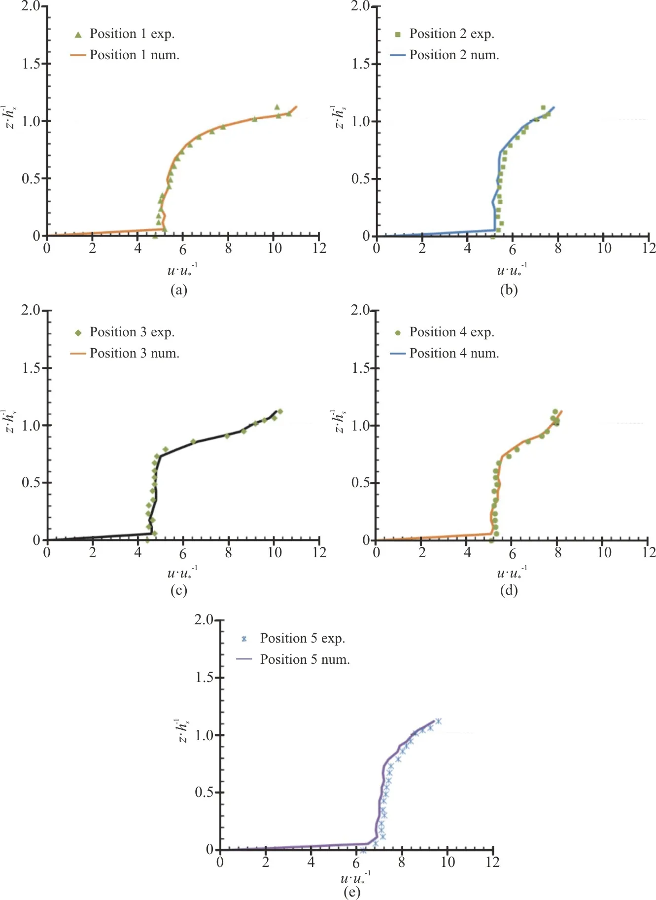
Fig.2 (Color online) Comparison of numerical and experimental data[21] (a)-(e) for the specific positions 1-5

Table 2 Experimental conditions[17]
1.6 Validation with discontinuous vegetation
The numerical and experimental results of mean stream-wise velocity at the specified positions are compared and presented in Figs.3(b)-3(d).In this figure, the horizontal axis represents the velocity which was normalized with the initial average velocity,whereas the vertical axis represents the flow depth which was normalized with the height of vegetation.It can be observed that the numerical data agrees well with the experimental data.However, due to the applicability of the wall function at the domain bed, a minor difference between the experimental and numerical results exists.
1.7 Numerical simulation
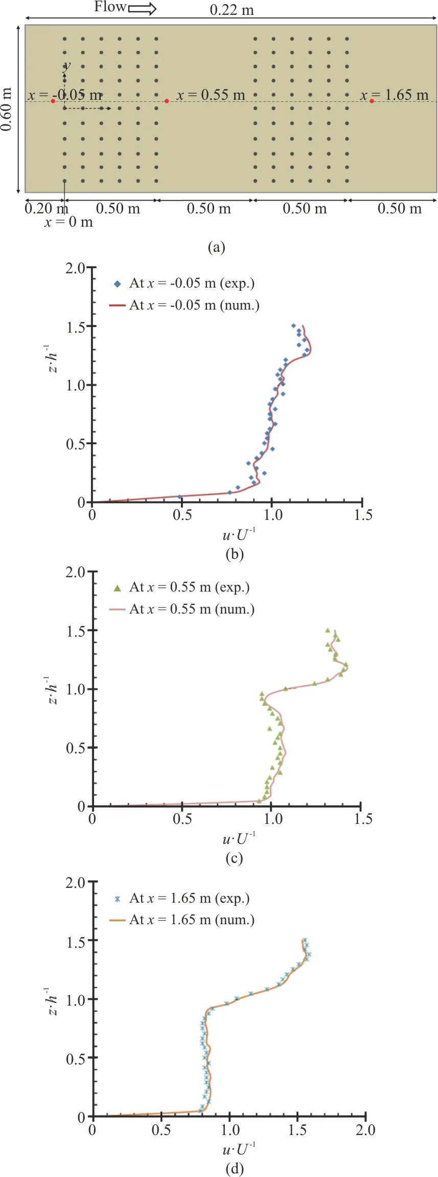
Fig.3 (Color online) Modeled geometry of Zhao and Huai[17] (a)vegetation arrangement and the specified positions (in red color), (b), (c) and (d) comparison of numerical and experimental results
The computational domain for the present study included 1.7 m long domain, consisting of vertically double layered (ht=0.152 m andhs=0.076 m ) and discontinuous vegetation patches (covering the entire domain width), keeping all the other geometric conditions similar to the one used in validation process of layered vegetation.Three cases 1-3 of varying vegetation density and patch length were adopted for this study.The hydraulic conditions of all the cases for the present research work are summarized in Table 3.The sketch of modeled domain for cases 1, 3 is shown in Figs.4(a)-4(d),whereas the specified positions in the last vegetation patch for all the cases are shown in Fig.4(e).These critical types of positions (upstream and downstream of vegetation elements) have also been investigated by Liu et al.[21].In the present study, two longitudinal sections i.e.,y=0.1500 m andy=0.1754 m were also adopted in order to investigate the turbulent flow properties.The section aty=0.1500 m passes through the centerline including the direct effect of shorter and taller vegetation structures, whereas, the section aty=0.1754 m was adopted as the distance of 0.0254 m from the centerline in theydirection is relatively appropriate to avoid the significant influence of the wake behind vegetation structures at the center line (y=0.1500 m).A minimum interval size of 0.002 m was used in the present case study mesh.The tri-pave mesh used for the present study provided approximately 1.3×10⁶grid points with 170×150×50 nodes in the longitudinal, transverse and vertical directions, respectively.In the present three cases 1-3, all the boundary conditions for the numerical model setup were kept the same.The mass flow rate (Q) and water depth (z) for all the cases were kept 11.4 L/s and 0.094 m, respectively.
2.Results and discussion
2.1 Mean flow properties
The simulated mean stream-wise velocity profiles at four selected positions are shown in Figs.5(a)-5(c).Takemura and Tanaka[23]demonstrated that the computing position can be a noteworthy feature while observing the structure of vegetated flow.The velocity was prepared non-dimensional with reference to average velocity (U), and the flow depth was normalized with reference to smaller vegetation height(hs).Figures 5(a)-5(c) shows that the velocity magnitudes are almost zero near the bed at all the specific positions.The velocity then began to increase along the depth of flow.The velocity profiles remained almost constant towards the top of vegetation whereas the profiles showed fluctuations at the top of submerged vegetation i.e.,z/hs=1.
Inside the smaller vegetation i.e.,z/hs<1, the stream-wise velocity profiles for all the three cases suffered larger fluctuations at distance of 4ddownstream of larger and smaller vegetation elements(positions 1, 2), whereas velocities upstream of smaller vegetation element (position 3) and free streamregion (position 4) have larger magnitudes and do not exhibit large fluctuations (Figs.5(a)-5(c)).The spatial fluctuations in the flow velocity occurring within the smaller vegetation are due to the vertical vortex behind the cylinder, which transfers the momentum from upper part to the lower part[11].Except position 2(located directly downstream of larger vegetation element) in all the cases, there is an upsurge in the magnitudes of stream-wise velocity just above the top of smaller submerged vegetation i.e.,z/hs=1.This is due to the absence of resistance offered by the vegetation above the top of smaller submerged vegetation and the exchange of momentum between the top of submerged vegetation and the flow.The fluctuations in the profiles of mean velocity for case 1 are evidently low (Fig.5(a)) as compared with case 2(Fig.5(b)).Due to high density of vegetation(Ss/d=4andSt/d=8) in case 2 and more resistance and turbulence offered by it, the profiles of mean stream-wise velocity showed relatively large fluctuations within the smaller vegetation i.e.,z/hs<1, especially in the regions directly downstream of small and tall vegetation elements(positions 1, 2, respectively) as compared with case 1 having sparse vegetation density (Ss/d=8andSt/d=16).The velocity profiles of case 3 (Fig.5(c))are more stable in both lower and upper vegetation layers and show no noteworthy difference as compared with the profiles of case 1 (Fig.5(a)).

Table 3 Hydraulic conditions
Figures 5(d)-5(f) and 5(g)-5(i) shows the transverse (v) and vertical (w) velocity profiles,respectively at the specified positions.It can be observed that, overall very low (close to zero)transverse and vertical velocities at all the positions are present as compared with that of stream-wise velocities.However, within the smaller vegetation i.e.,z/hs<1, relatively large fluctuations in the profiles(indicating deflection in the flows) are found in the regions located directly upstream and downstream of vegetation (positions 1-3) as compared with the profiles observed in free stream region (position 4).This effect is due to the resistance of the vegetation structures which offers more turbulence in the regions directly upstream and downstream of it.Similar to the stream-wise velocity, the profiles of transverse and vertical velocity in case 2 i.e.,Ss/d=4 andSt/d=8 (Figs.5(e), 5(h)) also showed relatively large fluctuations within the smaller vegetation i.e.,z/hs<1 in comparison with that of case 1 i.e.,Ss/d=8 andSt/d=16 i.e., (Figs.5(d), 5(g)).Also, the vertical profiles in case 3 (Figs.5(f), 5(i))are observed to be more stable as compared with that of case 1 (Figs.5(d), 5(g)), showing no significant difference.Moreover, in almost all the cases, a small flow deflection in the form of maximum positive and negative vertical velocities occurred at the top of smaller submerged vegetation i.e.,z/hs=1 (Figs.5(g)-5(i)) for all the positions.However, the flow deflection in this region i.e.,z/hs=1 is strong for the positions located upstream and downstream of the smaller submerged vegetation structures i.e., positions 3, 1, respectively.
The normalized mean stream-wise velocity on the longitudinal planes i.e.,y=0.1754 m andy=0.1500 m for all the cases have been presented in the form of contours plots (Figs.6(a)-6(f)).It can be observed that the velocity is greatly affected within the vicinity of vegetation, and a clear difference among the vegetated and non-vegetated regions can be witnessed.For sectiony=0.1754 m, velocities are observed to be increased in the vegetation patch regions comparative to the gap regions (Figs.6(a), 6(c)and 6(e)), whereas due to the reason of direct influence and hindrance of vegetation, reduction in flow velocities for sectiony=0.1500 mis observed in patch regions as compared with the gap regions(Figs.6(b), 6(d) and 6(f)).The stream-wise velocity is also observed to be decreased close to the domain bed,because of the effect of flow opposition offered by the domain bed.There is an abrupt fall of velocities directly after the large and small vegetation elements and velocities transfer to negative range in those regions (Figs.6(b), 6(d) and 6(f)).In the velocity contour plots through sectiony=0.1500 m, it can be easily observed that the deceleration effect resulted due to large vegetation is prominent.The velocity is comparatively small directly behind the large vegetation and increases progressively towards the top of short vegetation downstream.A thin separation with a high level of flow rate occurs in the upper regions of small vegetation.
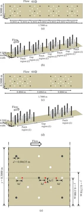
Fig.4 (Color online) Schematic sketch and 3-D representation for ((a), (b)) case 1, ((c), (d)) case 3, and (e) critical positions in the last vegetation patch of all the cases 1, 2 and 3.The white circles represent smaller vegetation elements whereas the black circles represent larger vegetation elements
The flows that meet the patches show noteworthy variations (Figs.6(a)-6(c)).A visible positive connection between the vegetation density and velocity development occurs for the overlying flow (z>hs).However, the influence of the patch distribution is not obvious in this zone.An upsurge of velocity at the top of submerged vegetation i.e.,z=hsis observed for all the cases.This is due to the shear layer formed on the top of submerged vegetation which promotes the vertical exchange of momentum.Also, in the previous studies[21,24], the faster and high-velocity region is found above the short layer in case of submerged vegetation.The variation of velocity within the patch as well as gap regions is relatively more in four patch case (Figs.6(a1), 6(a2)), as compared with that of two patch case (Figs.6(c1), 6(c2)), showing that the flow is relatively stable when the patch length is increased.Hence, the disruption in the flow is more significant when the number of patches and gaps increases.The mean stream-wise velocity abruptly increases and decreases within the patches and gaps, respectively for high vegetation density i.e.,Ss/d=4 andSt/d=8(Figs.6(b1), 6(b2)) as compared with sparse cases i.e.,Ss/d=8 andSt/d=16 (Figs.6(a1), 6(a2) and 6(c1), 6(c2)).The mean velocities fail to recover their usual patterns due to the impact of discontinued layered vegetation patches beyond the downstream edge specially in sparse case (Figs.6(a1), 6(a2)).It requires a sufficient distance to maintain its new stable condition.
Figures 7(a)-7(c) shows the simulated contour plots of mean stream-wise velocity on horizontal planes ofx-ydirection for all the cases 1-3.In order to clearly understand the flow structure, two horizontal surfaces were investigated, one atz=0.094 m (top free surface of the flow), whereas the other atz=0.076 m(the top of smaller submerged vegetation), respectively.It is clearly visibly for all the cases that mean velocity has larger magnitudes in the patch regions as compared to that of gap regions, except for the regions directly downstream of vegetation.The sheltering effect of the patches causes the velocity to slow down in the gap regions.Almost zero velocity magnitudes can be observed in the regions just behind the vegetation structures, followed by strong wake regions of low velocities.A clear flow separation around individual cylinders is visible with maximum and medium magnitudes of velocity in upper and lower regions and in the zones directly upstream of each vegetation structure, respectively.This flow separation resulted due to the large turbulence in flow over the circular cylinders.However, the intensity of wake formation and flow separation is relatively low in the case of dense vegetation (Figs.7(b1), 7(b2)) as compared with the sparse vegetation cases (Figs.7(a1), 7(a2) and 7(c1),7(c2)).This is due to the reason that in dense vegetation arrangement (Ss/d=4 andSt/d=8), the size of the wakes downstream of the individual cylinders was gradually compressed with a decrease in porosity as the passage of the fluid flow narrowed.This result is in consistency with the results observed in previous research studies[23,12-13].Moreover, the velocities are almost zero or minimum close to the side walls because of the resistance offered by the walls.
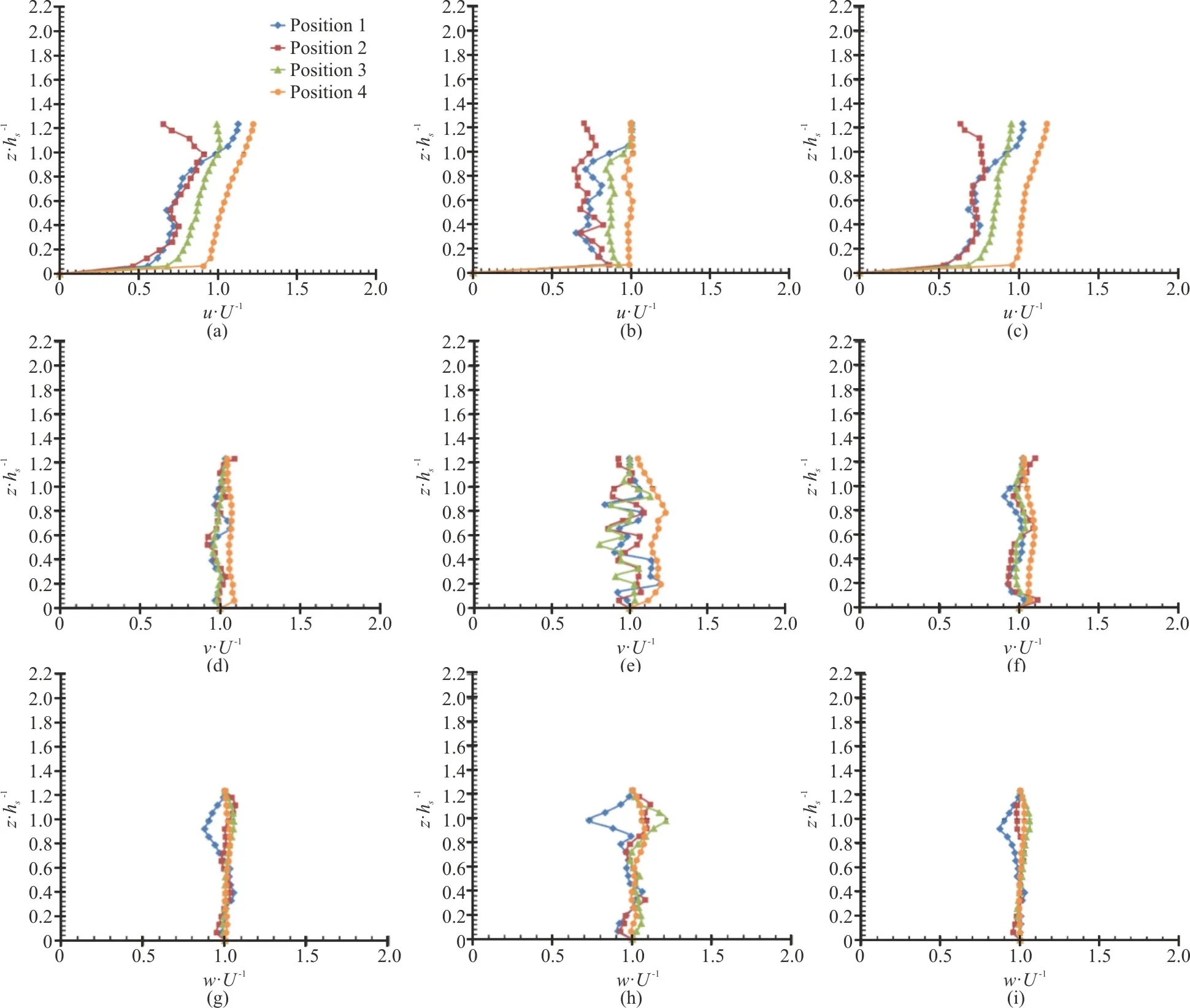
Fig.5 (Color online) Stream-wise (u/ U), transverse (v/ U) and vertical (w/ U) velocity profiles at specified positions (i.e.,1, 2, 3 and 4) for ((a), (d), (g)) case 1, (b, e, h) case 2, and ((c), (f), (i)) case 3
For the sparse vegetation case i.e.,Ss/d=8 andSt/d=16 (Figs.7(a1), 7(a2)), overall higher magnitudes of mean stream-wise velocities are found in the gap as well as patch regions of both the horizontal surfaces (z=0.094 m andz=0.076 m ),as compa red with the dense v egetati on cas e i.e.,Ss/d=4andSt/d=8 (Figs.7(b1),7(b1)).This effect of low flow velocities in dense vegetation case is due to the large flow opposition offered by the increased number of vegetation elements.However,the effect of patch distribution form in the sense of varying the patch as well as the gap length (L) on the flow structure in case 3 is almost observed to be relatively minimum (Figs.7(c1)-7(c2)) as compared to case 1.It means that the turbulence in the flow mainly depends on the vegetation density, and the flow structure variation by the distribution form is relatively low under the same hydraulic conditions.
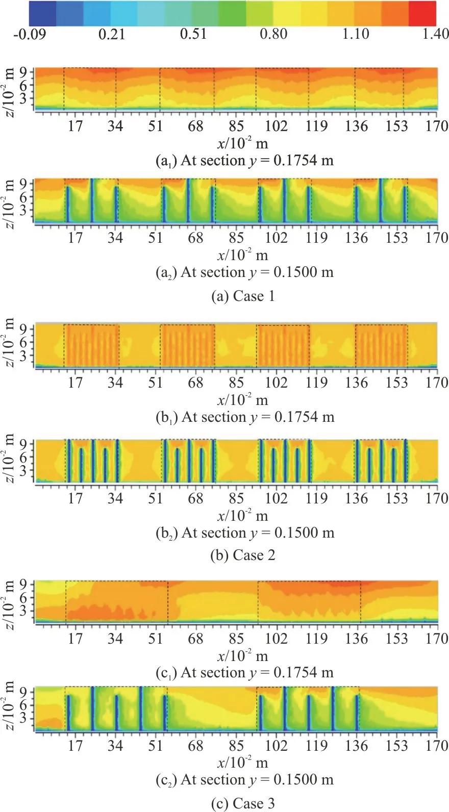
Fig.6 (Color online) Contour plots of the mean velocity(u/ U).The area occupied by the patches is represented by dashed boxes
The depth averaged mean velocity plotted along the longitudinal sectiony=0.1754 m for all the three cases is shown in Figs.8(a)-8(c).For cases 1, 2,the patches range from 0.1388 m to 0.3420 m, 0.5452 m to 0.7484 m, 0.9516 m to 1.1548 m and 1.3580 m to 1.5120 m, whereas for case 3, the patches range from 0.1388 m to 0.5452 m and 0.9516 m to 1.3580 m on the longitudinal axis of Figs.8(a)-8(c).It is observed that the flow through the patches is non-uniform,although the flows at the upstream and downstream regions seem to be uniform.The mean flow velocity is considerably larger in the vegetation patch zones as compared with the gap zones.This result is consistent with that observed in Figs.6(a1), 6(b1) and 6(c1).For all the cases (1, 2 and 3), vegetation blockage within the patches show noteworthy difference with that in the gaps without the vegetation.The sheltering effect of the patches results in the velocity to reduce in the gap zones as compared with those in the patch zones.The rising velocities in the patches are rational due to the hindrance of the vegetation.According to the ecological point of view, the physical atmosphere of the gap zones is suitable for aquatic life.Due to the dense vegetation arrangement (Ss/d=4 andSt/d=8), case 2 has more rise and fall in mean velocities as compared with case 1 having sparse vegetation arrangement (Ss/d=8 andSt/d=16).Larger fluctuations in mean velocity values are observed for cases 1, 2 (Figs.8(a), 8(b)) as compared with case 3 (Fig.8(c)), showing that greater number of patches and larger vegetation density offer more disruption and turbulence to the flow.These results of stable velocity profiles for Case 3 show consistency with the results discussed in Figs.5, 7.
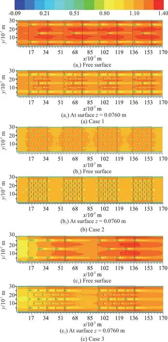
Fig.7 (Color online) Contour plots of the mean velocity(u/ U) along the x-y plane.The area occupied by the patches is represented by dashed boxes
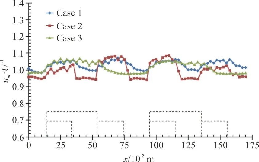
Fig.8 (Color online) Fluctuations of the depth averaged mean velocity along the length of domain for (a) Case 1, (b)Case 2 (c) Case 3.The small dashed boxes show the location of the patches for cases 1, 2, whereas the large dashed boxes show the location of patches for case 3
2.2 Turbulence properties
2.2.1 Turbulent kinetic energy
The simulated depth averaged turbulent kinetic energy (TKE) along sectiony=0.1754 m for all the cases 1-3 is shown in Figs.9(a)-9(c).The kinetic energy was normalized with respect to2U.Figs.9(a)-9(c) shows the effect of vegetation density, patch length and distribution form along the domain length.A clear difference in TKE values exists between the sparse (case 1) and dense vegetation cases (case 2).The TKE values for the dense vegetation case (Fig.9(b)) are significantly higher as compared with the sparse vegetation case (Fig.9(a)) in both patch as well as gap regions.This difference in magnitudes of turbulent energy for cases 1, 2 shows that larger turbulence in flow is present when vegetation is dense(Ss/d=4 andSt/d=8).The difference in TKE values due to the variation in distribution form in case 3 (Fig.9(c)) is not clear as compared with that of case 1 (Fig.9(a)).However, slightly lower magnitudes of TKE exist in the gap regions for case 3 showing a small relative difference with the case 1.Moreover,due to the presence of vegetation, a saw-tooth distribution of turbulent energy can be observed within the vegetation patch regions for all the three cases (Figs.9(a)-9(c)).The effects of saw-tooth dissemination are primarily prominent in vegetation patches.However, this saw-tooth phenomenon of depth-averaged turbulent kinetic energy within the vegetation is difficult to detect in experimental study.Overcoming this difficulty is one of the benefits ofk-εmodel.
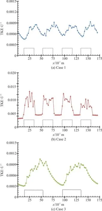
Fig.9 (Color online) Depth averaged turbulent kinetic energy along the domain length.The dashed boxes indicate patch regions
The distribution of non-dimensional turbulent kinetic energy along the domain length (Figs.9(a)-9(c)) further shows an obvious difference among the vegetation patch and gap regions.For all the cases,there are larger magnitudes of kinetic energy in the vegetation patch regions as compared with the gap regions.There is a noteworthy rise in turbulent energy at the upstream edge of the vegetation patches,whereas a fall in energy can be witnessed at the downstream edge of the layered vegetation patch regions.The maximum magnitudes of TKE are observed to fall within the patch regions for cases 2, 3,whereas the maximum TKE values for Case 1 are observed at the downstream edge for the first two patches only.This may be due the prevailing effect of the vegetation patches and generation of wakes behind individual cylinders as discussed in Figs.6(a), 6(b)and 7, respectively.The maximum TKE values for all the cases locate in the saw-tooth distribution of patch regions, within which a rise and fall in TKE values can be observed.This effect resulted due to the reason that when flow passed through the patch regions, it became relatively non-uniform due to the presence of vegetation elements.As the flow reached in the adjacent regions (having relatively high flow velocity)of the vegetation elements, the turbulent energy showed a relatively falling trend, whereas when the flow passed through the downstream vicinity (wake)regions of the vegetation elements, a rise in TKE values observed due to relatively high production of energy in this region.The rise and fall in the saw-tooth distribution observed for case 2 are relatively more due to increased number of vegetation elements in the dense patches as compared with case 1.However, overall a rising trend for TKE values has been observed within the patch regions as compared with the gap regions for all the cases.This result is in similarity with the results of previous researchers[11,17].
2.2.2 Turbulent intensity
Figures 10(a)-10(c) depicts the simulated turbulent intensityprofiles in the form of percentage (%) at the selected four critical positions 1-4 for all the cases (1, 2 and 3).The intensity profiles for all the cases at positions 1, 2(which are located directly behind the small and large vegetation structures, respectively) showed large amount of turbulence and larger fluctuations, followed by sharp inflections at the top of submerged vegetation i.e.,z/hs=1.Whereas, relatively medium fluctuations in intensity percentages are found at position 3 (located upstream of small vegetation), and almost very small fluctuations in the intensity profiles can be observed at position 4 (located in free stream region).This shows that the regions directly upstream and downstream of vegetation are of great importance while investigating the turbulent flow properties, and that the vegetation structures cause resistance and turbulence to the flow.
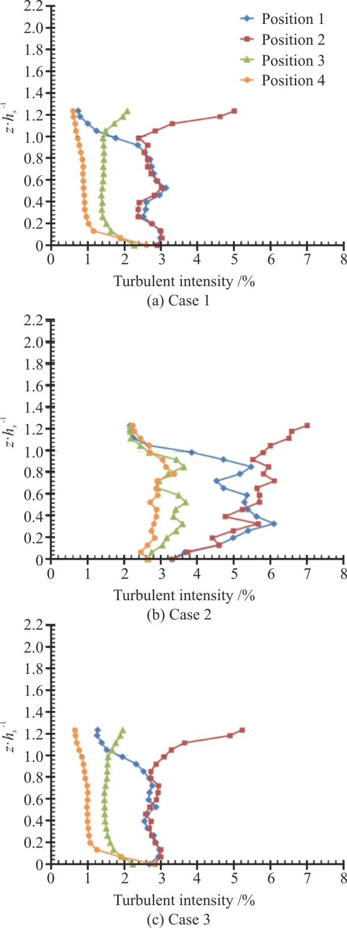
Fig.10 (Color online) Turbulent intensity (%) profiles
With double layered vegetation, the larger vegetation decreases the velocity of the flow abovez=hs, and causes the momentum exchange to reduce at the boundary of the shorter vegetation.This results in the turbulent intensity to be almost constant for approximately 70% of the flow depth within the short vegetation i.e.,z/hs<1 for cases 1, 3 (Figs.10(a),10(c)).Except for case 2, where vegetation density is double (Ss/d=4 andSt/d=8) as compared to cases 1, 3 (Ss/d=8 andSt/d=16), the turbulent intensity is almost constant for 30% of the flow depth with in the short vegetation (Fig.10(b)).Moreover,large difference in percentage of turbulent intensity can be observed for case 2 i.e., dense vegetation case(Fig.10(b)) as compared with cases 1, 3 i.e., sparse vegetation cases (Figs.10(a), 10(c)).These larger fluctuations in profiles of turbulent intensity and large percentage of turbulence for case 2 are resulted due to the effect of more resistance and turbulence offered by dense vegetation patches.This effect is similar to the findings reported by Stoesser et al.[25].It was also found by Nezu and Onitsuka[26]that the flow instability increases with an increase in vegetation density due to large scale of vegetation.Although there is no difference in percentage of intensity between cases 1, 3 (Figs.10(a), 10(c)), the profiles of turbulent intensity for case 3 are more stable and the fluctuations in it are observed to be low as compared with case 1.
The flow turbulence through discontinued layered vegetation is reflected by the distribution of turbulent intensity (Figs.11(a)-11(c)).Figures 11(a)-11(c) shows the contour plots of turbulent intensity (%) along the longitudinal sectionsy=0.1754 m andy=0.1500 m captured by the numerical model for all the cases (1, 2 and 3).The presence of discontinued layered vegetation has a large influence on the turbulent intensity inside the vegetation regions.For dense vegetation case i.e.,Ss/d=4 andSt/d=8 (Figs.11(b1), 11(b2)),larger percentage of turbulent intensity (13%) can be witnessed as compared with sparse vegetation cases i.e.,Ss/d=8 andSt/d=16 (Figs.11(a1), 11(a2)and 11(c1), 11(c2)), showing maximum of 9% of turbulent intensity.This result is consistent with that observed in Figs.10(a)-10(c).However, turbulence percentage is relatively unaffected due to distribution form of the patch for case 3 (Figs.11(c1), 11(c2)).Hence, for the same vegetation density (Ss/d=8 andSt/d=16), the turbulence percentage for the two patch case (having large patch and gap length) i.e.,case 3, is almost unaffected in comparison with that of four patch case i.e., case 1.The distribution of intensity through vegetation patches is quite different from the regions without vegetation.For all the cases,low turbulence in flow is found in the gap regions comparative to the patch regions.The intensity distribution is more uniform in regions away from the bed in view of the influence of vegetation.Along sectiony=0.1754 m, the difference in turbulent intensity (%) in patch areas is low as compared with the gap areas due to no effect of direct vegetation(Figs.11(a1), 11(b1) and 11(c1)).Whereas, the direct influence of vegetation i.e., along sectiony=0.1500 m, on intensity distribution can be observed in Figs.11(a2) , 11(b2) and 11(c2).Large amount of turbulent intensity can be visualized just behind the vegetation elements as well as close to the domain bed (Figs.11(a2), 11(b2), 11(c2)).Greater amount of intensity concentrates close to the edge of vegetation.The intensity regains its average value after the patch regions at a certain distance.A sharp slope of the intensity can be seen at the downstream edge of vegetation patches due to discontinuity in vegetation patches.The outcomes demonstrate that turbulence at large scale is present within the patch regions as compared with the gap regions.
3.Conclusions

Fig.11 (Color online) Simulated contour plots of turbulent intensity (%)
Understanding the flow phenomena in the area surrounding the vegetation is important when modeling or studying the open channel flow.The present study was aimed at investigating the flow structure around discontinued and double-layered rigid vegetation patches in an open channel.The numerical analysis carried out in this work, examining the flow patterns through discontinued layered vegetation, had shown to us significant conclusions:
(1) The mean stream-wise velocity profiles showed large fluctuations in space within the smaller vegetation and low magnitudes directly behind the vegetation structures.The fluctuations in the flow velocity are caused by the vertical transfer of momentum from upper to lower part in varying vegetation layers.This also shows that the flow is more disrupted in the regions directly behind the vegetation structures.
(2) Within the lower (short) vegetation layer i.e.,z/hs<1, the velocities were observed to be low comparative to the upper (taller) vegetation layer i.e.,z/hs<1.Inflection points in the velocity profiles resulting in higher magnitudes were noticed at the top of smaller submerged vegetation due to the exchange of momentum between the canopy top and water interface.
(3) The flow over the smaller and larger vegetation cylinders strongly enhanced the turbulence, which led to the separation of flow.Moreover, the hinder effect of larger vegetation was higher than that of short vegetation because of the flow velocity differences and emergent condition of larger vegetation.However, the shorter layer in double layer vegetation also plays an important role in reduction of flow and offering resistance.
(4) Due to blockage of vegetation patches, the depth averaged mean velocity increased as the flow passed through the patch regions compared with that of gap regions.This classifies that the gap regions acquire low velocities which is favorable for sediment deposition and aquatic organisms for their physical atmosphere.
(5) Turbulence was intensified in the vegetation patch regions.A noticeable rise in turbulent kinetic energy and turbulent intensity was witnessed in the patch regions compared with that of gap regions.
(6) The response of the flow approaching the discontinuous and layered dense vegetation patches(covering the whole section in cross-stream direction)was more turbulent in comparison with that of sparse vegetation patches.Higher percentage of turbulence is found for the dense arrangement of layered vegetation as compared with that of sparse arrangement.It indicates that the flow opposition mainly depends on the entire vegetation volume.
(7) The turbulent flow structure shows a considerably positive connection with the density of vegetation.Moreover, the increase of patch and gap length results in a more stable flow structure.On contrary, the turbulence is comparatively unaffected by the distribution form of the patch.
Thek-εturbulence model has shown to be efficient in modeling the turbulent flow features through discontinued and vertically layered vegetation.Further research is required to investigate the effects of varying discharge and Reynolds number conditions for layered and discontinuous vegetation.Also, in future research works; sediment deposition within the gaps needs to be investigated and quantified.
杂志排行
水动力学研究与进展 B辑的其它文章
- A review on flow-induced vibration of offshore circular cylinders *
- Principal coordinates and principal velocity gradient tensor decomposition *
- Numerical study of morphological characteristics of rotational natural supercavitation by rotational supercavitating evaporator with optimized blade shape *
- Estimation of the turbulent viscous shear stress in a centrifugal rotary blood pump by the large eddy particle image velocimetry method *
- POD analysis on vortical structures in MVG wake by Liutex core line identification *
- Importance of incorporating systemic cerebroarterial hemodynamics into computational modeling of blood flow in intracranial aneurysm *
