A review on flow-induced vibration of offshore circular cylinders *
2020-12-02JiasongWangDixiaFanKeLin
Jia-song Wang , Dixia Fan, Ke Lin
1.Department of Engineering Mechanics, School of Naval Architecture, Ocean and Civil Engineering, Shanghai Jiao Tong University, Shanghai 200240, China
2.State Key Laboratory of Ocean Engineering, Shanghai Jiao Tong University, Shanghai 200240, China
3.Key Laboratory of Hydrodynamics (Ministry of Education), Shanghai Jiao Tong University, Shanghai 200240,China
4.Department of Mechanical Engineering, Massachusetts Institute Technology, Cambridge, USA
Abstract: As a fundamental fluid-structure interaction (FSI) phenomenon, vortex-induced vibrations (VIVs) of circular cylinders have been the center of the FSI research in the past several decades.Apart from its scientific significance in rich physics, VIVs are paid great attentions by offshore engineers, as they are encountered in many ocean engineering applications.Recently, with the development of research and application, wake-induced vibration (WIV) for multiple cylinders and galloping for VIV suppression attachments are attracting a growing research interest.All these phenomena are connected with the flow-induced vibration (FIV).In this paper, we review and give some discussions on the FIV of offshore circular cylinders, including the research progress on the basic VIV mechanism of an isolated rigid or flexible cylinder, interference of multiple cylinders concerning WIV of multiple cylinders, practical VIV suppression and unwanted galloping for cylinder of attachments.Finally, we draw concluding remarks, give some comments and propose future research prospects, especially on the major challenges as well as potentials in the offline/online modelling and prediction of real-scale offshore structures with high-fidelity CFD methods, new experimental facilities and applications of artificial intelligence tools.
Key words: Fluid-structure interaction (FSI), vortex induced vibration (VIV), wake-induced vibration (WIV), flow-induced vibration (FIV), galloping, offshore engineering, circular cylinder, VIV suppression
Introduction
Bluff body structures can be found in a wide variety of industrial fields, including all kinds of mechanical, civil, offshore, and aerospace engineering.Especially, in the offshore engineering, most structures are circular cylinders, for instance, subsea cables for electronic communication and power transmission, pipelines for fluid transportation, and drilling or production risers that connect the floating platform and the underwater well head (Instead of an isolated riser, multiple risers bundle are implemented in the tension leg platform (TLP) or spar platform to save spaces and cost).When these structures are placed in a flow, over a wide range of the Reynolds number (Re), alternating vortices form at the aft-body of the structure and shed into the downstream wake with a coherent and varied flow pattern of vortices.Therefore, the vortex-induced forces on the structure displays a nature of periodicity, resulting from the phenomenon of the flow-induced vibration(FIV).
Vortex-induced vibration (VIV), generally of isolated cylinder, wake-induced vibration (WIV) of multiple circular cylinders, as well as the galloping for complicated cylinder (such as cylinder with attachments) are well-known FIV phenomena when the bluff body structures interact with the shedding vortex.These phenomena have been attracting a growing research interest in the field of fluid-structure interaction (FSI) for the past several decades due to its theoretical significance and rich physics.In addition,the study of FIVs has also been considered important for engineering practices as these problems appear in numerous offshore applications such as risers and pipes (Note that this review only focus on the external fluid flow induced vibration, not involving the FIV due to the internal fluid flow).Nowadays, the exploration of offshore oil and gas moves quickly from shallow into deeper water, and faces harsher environmental constraints, such as stronger waves and faster currents.Therefore, in order to prevent offshore structures from severe fatigue failure or collision accidents[1], FIV prediction and control become increasingly critical at both the system design stage and the operation phase.
FIVs of circular cylinders are highly non-linear FSI problems, which poses a great difficulty in understanding the underlying mechanisms.The problem concerns several fundamental fluid dynamics phenomena[2]: boundary layer separation, laminar and turbulent flow, shear layer development and rolling up,unsteady vortex shedding, and even wake interference.In addition, as a highly coupled fluid-structure system,the variation of the structural attributes, such as mass,damping, rigidity, boundary condition, aspect ratio,etc., can alter the FIV response considerably[3].In short, the complex nature of the problem makes the complete systemic exploration of the entire basic FIV mechanism almost intractable.Therefore, how to give a reliable prediction of the vibration response and then how to suppress the vibration are still the essential issues for the engineers and scientists to address nowadays.
In the current practice, the industry still relies heavily on empirical data acquired from the model testing in a well-controlled laboratory setting to predict FIVs, which poses the problem of the different(lower) Reynolds number (Re) and the different(smaller) structural scale compared with the real-world applications[4].For example, for the full-scale VIV data monitored by Cornutt and Vandiver[5]for a drilling riser of 360 m water depth in the Schiehallion field of West of Shetlands, theRerecorded were frequently above 105, and such a largeRecan be rarely reached in laboratory experiments.Questions thus can be raised whether the experimental test data can be directly applied to the real engineering geometries and whether there is or there is no scale influence on the structure geometrical size.To the authors’ best knowledge, these questions have not been well addressed yet.
Apart from the model testing and semi-empirical modeling, CFD simulation is another essential tool to predict FIVs.The simulation result can provide not only structural response but also a detailed description of the flow pattern, which helps to understand the governing physical mechanism in great detail.However, due to the expensive computational cost,most of the CFD-based simulation has been focused on offshore problems in model scales.Nevertheless,we foresee that with the increasing computational resources and simulation accuracy, using CFD to study FIVs may be the proper or even the best choice soon in the future, as the experimental test is constrained by many factors, such as facility availability and capacity limits, model scale limits,difficulty of current profile generation, and cost and schedule concerns.As a matter of fact, the research group of Wang et al.[6-8]had firstly carried out a full scale of FSI modeling for the drilling riser with diameter of 0.5334 m, length of 500 m and 800 m for uniform flow and 343 m for sheared flow under high Reynolds number condition.Their results showed the riser response characters of large amplitudes, multifrequencies, high-order multiple vibration modes, not negligible IL large amplitude response, top tension influence, various vortex shedding modes, and travelling/standing wave mixed responses.Although the work has only provided some preliminary result, it has paved a research vision to achieve the full-scale FIV prediction based on the advanced computational technique for real size of slender structures and then to control or suppress VIV of risers or other slender structures, ensuring the safety of structures.
Nevertheless, FIV of circular cylinders is a rich and active research field for over five decades, and various review papers have conceptually documented the problem from different perspectives, including the intrinsic structural and hydrodynamic nature of the rigid cylinder vortex-induced cross-flow (CF)vibration[9-11], various experiment and modeling efforts on an isolated flexible cylinder in the uniform flow[12], various semi-empirical models of VIV[13],and the complex wake morphology due to the hydrodynamic interference of two rigid stationary cylinders[14-15].However, over the last decade, a lot of progress has been made from the fundamental studies to real applications, from simple to complicated problems, and from well-established traditional research methods to novel intelligent ones.Therefore,in this review, compared with the past review papers,we do not focus on the advances of empirical or semi-empirical models, but concentrate on the recent advancement in understanding of offshore structures FIVs, especially on the basic circular cylinder FIV mechanism, concerning principally on combined-CF-and-inline (IL) VIVs of an isolated rigid or flexible cylinder in Section 1, VIVs and WIVs of multiple interfering cylinders in Section 2, and practical issues of the VIV suppression and the unwanted galloping for cylinder with attachments in Section 3, where galloping as a new problem in offshore engineering arouse increasing research interesting.At the end of each section, a brief summary will be given, together with several open research questions.At last, we provide our concluding remarks and propose future research prospects.
1.VIV of an isolated cylinder
1.1 VIV of the rigid cylinder
Rigid cylinder VIV has been extensively studied over the last five decades, but, much physics behind this complex FSI problem, such as the role of the added mass[3,16]and high order oscillatory fluid forces[17-18], is still elusive and remains the core of the FIV modelling.In this section, we briefly review some of the main concepts in the rigid cylinder VIV and emphasize on the recent progress of some new physics insights in the simplest form of this problem,the uniform circular rigid cylinder oscillating in the uniform flow.
1.1.1 Elastically-mounted rigid cylinder in uniform flow
For the canonical FSI problem of the flexibly mounted cylinder that is allowed to vibrate only in the cross-flow (CF) direction[19], it has been well established that over a broad range of incoming velocities, there exist different regimes of response as initial, upper and lower branches[20]and different vortex shedding modes (2S, 2P, P+S, etc.)[21].One of the most important concepts of such a problem is“lock-in”[22], wherein the vortex shedding frequency is entrained to coincide with the CF vibration frequency.During “lock-in”, moderate response amplitudes typically self-limit to approximate one diameter, and a wide range of synchronization frequencies are observed[23].The vortex shedding frequency can differ from the Strouhal frequency of a fixed cylinder,because the relative motion between the vibrating cylinder and the shed vortices can significantly alter the effective fluid added mass, resulting in a variable natural frequency as a function of stream velocity[2].
If the cylinder is allowed to move in both the inline (IL) and the CF directions, considerable differences can be observed for the cylinder CF vibration response, especially for the low mass ratio model, compared with that of the CF-only vibrating cylinder[24].This is due to the fact that the IL motion affects the CF vibration substantially, even though the IL motion is usually 3-6 times smaller than the CF motion.In experiments, the CF displacement can reach more than 1.5 diameter[25], and the lock-in frequency range is enlarged[26].Phenomenon of dual resonance is observed that both the IL and the CF responses are in “lock-in”, which is made possible via altering the effective added mass in both directions[26].One of the most important findings for the rigid cylinder combined-IL-and-CF free vibration is the role of the phase angleθof the cylinder orbit.As the cylinder IL response is normally twice the frequency of the CF response due to the fact that the oscillatory drag component is twice the frequency of the oscillatory lift force, the cylinder will move in a“Figure-8” trajectory, and the differentθwill result in a significant variation in the cylinder orbit directions.In addition,θis found to have a strong influence on the fluid forces and motions of the oscillating cylinder[19].It is observed that [0,]θ∈ π of counter-clockwise (CCW) trajectory (the cylinder moves upstream at the peak of the cylinder orbit,which is first defined by Dahl et al.[25]) favors the positive energy-in from the fluid to the structure and hence the rigid cylinder is more likely to vibrate with a CCW trajectory[27].In addition, the occurrence of higher-order harmonics (3rdand tthharmonics) in the lift force is found to be correlated with specific values ofθ, as a result of the timing alteration between cylinder motion and the shedding vortices in the near wake by the IL motion[28-29].Furthermore, with the existence of the IL motion, new type of the vortex shedding pattern is observed, such as “2T” mode[30].
1.1.2 Rigid cylinder forced vibrations with prescribed motions
To quantify the significant variations of the fluid forces on the oscillating cylinder, forced vibration[31]experiments are conducted on a rigid cylinder in either the CF direction or the combined-IL-and-CF directions at prescribed frequencies and amplitudes.Rigid cylinder CF-only forced vibration experiments performed by Gopalkrishnan[32]systematically varied the true reduced velocityVr=U/(fD), and nondimensional CF amplitudeAy/D, whereUis the prescribed fluid velocity,fis the prescribed motion frequency(noticing that the true reduced velocityVris different from the reduced velocityUr=U/(fnD),wherefnis the natural frequency of the system vibration in the air/water),Ayis the prescribed motion amplitude andDis the cylinder model diameter.The result of the hydrodynamic coefficient in the experiment shows that regions of positive lift coefficient in phase with the velocityClv, denoting net energy transferred from the fluid to the structure over one motion period, are located in a certain range ofVrandAy/D, and the added mass coefficient in the CF directionCmycan vary significantly from a negative to a large positive value.The fluid forced measured from the forced vibration results in an accurate prediction of the rigid cylinder VIV in the CF direction.Figure 1 plots a good comparison between theClv=0 contour line and the CF displacement response of a zero damped elastically mounted cylinder in the uniform flow[19].In addition, these hydrodynamic coefficients have served as databases for fluid forces in semi-empirical flexible riser VIV prediction codes, such as Shear 7[33], VIVA[34]and VIVANA[35].
Combined-IL-and-CF vibration experiments[36]have been performed on the rigid cylinder with the IL vibration frequency 2 times of the CF vibration frequency.From the results,Clvis shown to be not only strongly dependent onVrandAy/D, but also onθas well.More specifically, the positiveClvis found to be largely associated withθ∈[0,π] of CCW trajectory, shown in Fig.2(a).This result is compatible with the phenomenon observed in the cylinder free vibration[28].Furthermore,Cmy, like theClvis observed to have a strong relationship to the cylinder orbit orientation as well, shown in Fig.2(b).
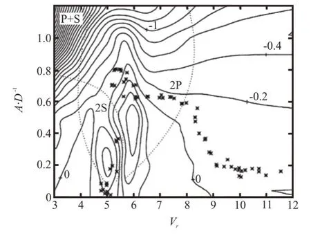
Fig.1 An comparison between the amplitude response of cylinder CF-only free vibration with zero damping (dot) compares well with the zero contour line of Cw acquired from the forced vibration experiment[19]
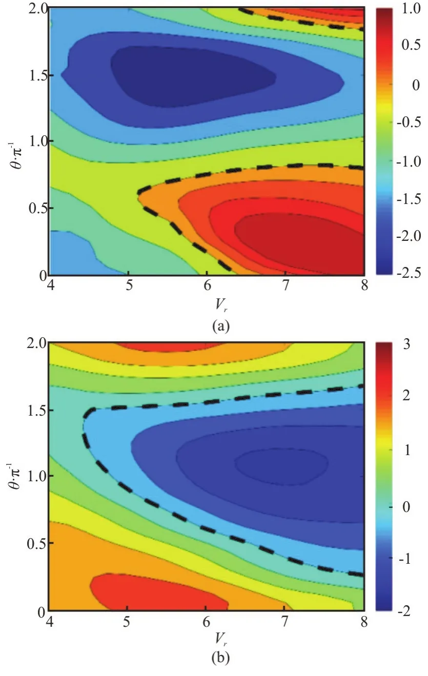
Fig.2 (Color online) Contours of Clv (a) and Cmy (b) versus θ/π and Vr at Ax/D=0.15 and Ay/D=0.60 [18].The black dashed lines highlight the contour line of Clv=0 and Cmy=0.The result shows that the phase θ difference between IL and CF trajectory has a strong effect on the hydrodynamic coefficients
Apart from the force measurement, the forced vibration experiment has also been used to map the wake patterns.Williamson and Roshko[21]first reported a map of wake pattern of “2S”, “2P” and“P+S” modes behind a CF-only forced vibrating rigid cylinder, which have also been identified in the rigid cylinder free vibration experiment[19].In addition,Carberry et al.[16]established a correlation between the wake pattern and hydrodynamic force on a controlled oscillating cylinder in the CF-only direction, where a slight change of the vibration frequency may result in a sharp change of the magnitude of the oscillatory lift force and the phase between the fluid force and cylinder motion, accompanied with a vortical wake mode switch.No comprehensive mapping has been conducted on the combined-IL-and-CF rigid cylinder vibration yet, but some preliminary observation[16]suggests that such a correlation among cylinder motions, fluid forces and wake patterns exists as well in the cylinder combined-IL-and-CF vibrations, andθis an important factor.
1.2 VIV of the flexible cylinder
When the aspect ratio of the cylinder becomes large, the structure becomes flexible.And when such a system is put in the steady oncoming flow, it is subject to vibrations caused by the vortical structures forming due to the distributed flow instability in its wake.In the last decade, researchers have made large progress in understanding some of the basic features of this FSI system and have succeeded in mapping some of the rigid model properties to the flexible system, including model scale and real scale of structures.
1.2.1 Structural response of a single flexible cylinder in uniform flow
Different from rigid cylinder, flexible model obtains multiple structural natural frequencies and vibration modes.The question hence is raised: at a given flow condition, for a given riser configuration(such as riser diameter, length, tension, bending stiffness, etc.), what mode and frequency the riser will vibrate in, and what relationship the CF and IL response will be for the flexible structure VIVs.
In the last decades, a tremendous effort has been devoted to study the structural response of the long slender flexible structure VIVs, and several carefully controlled laboratory experiments and numerical simulation help to shed some light on the physics of this problem[38-41].It is revealed that when the flexible cylinder with significant bending stiffness vibrates at low mode, its maximum amplitude resembles that of the rigid cylinder free vibration[42].Yet several large scale laboratory experiments and field observations reveals some new phenomena of the long flexible cylinder VIVs: chaotic IL and CF vibration of high modes with a strong traveling wave response span wise[43]is the character of these extremely long flexible cylinders VIVs.Besides, a lot of phenomena,such as the ratio of two between the IL and the CF vibration frequency, the enhanced total drag coefficient[44], and the strong third or higher harmonics in the CF direction[43]are observed.
Two of the most comprehensive experiments on the long flexible cylinder over a wide range of the reduced velocities have been conducted by Chaplin et al.[37]and Fan et al.[4]on models of different scales at different facilities.Need to point out here, in both experiments, the effect of the tension along the flexible structure is larger than that of the bending stiffness.Their results share a similar trend that the model responds with a narrow-banded single frequency, and the IL motion plays an important role in the CF vibration.In addition, they found separately that the maximum displacement of the flexible cylinder VIV exhibits a discontinuous response pattern during the modal group switch (the modal group is defined for the case of the same IL and CF dominant modes), accompanied with the jumping of the response frequency, shown in Fig.3.Fan et al.[4]explained that such a frequency and displacement jumping is a result of variation of the hydrodynamic coefficient distribution along the model, especially the fluid added mass.

Fig.3 (Color online) Experimental results of the displacement response in the CF direction for uniform flexible cylinders are from Chaplin et al.[37] (a) and Fan et al.[4] (b).The two experiments were conducted in different scale at different facilities, but the results displayed similar behaviors.When grouped with same modal group (same dominant mode in both the IL and the CF directions), the CF displacement is found to monotonically increases with the reduced velocity in the same modal group and discontinuously switch between different modal groups
1.2.2 The validity of the strip theory: Rigid vs.flexible cylinder
In general, the offshore industry still relys heavily on semi-empirical prediction tools for problems of flexible cylinder, whose flow characteristics and corresponding hydrodynamic forces are calculated from the experimental database with a fundamental assumption of the strip theory.These experimental databases are mainly obtained from the experiments on the rigid cylinder forced vibrations (discussed in Section 1.1.2).Certainly, CFD which solves the coupled problem of vibrating cylinder and ambient fluid flow together also commonly use the strip theory to implement series of 2-D CFD planes being vertical to the cylinder axis direction in order to avoid the unbearable simulation cost of full 3-D problem[40-41,45].
The key factor for the accurate prediction of flexible cylinder VIVs is the accuracy of the hydrodynamic coefficients applied.However, to begin with,it is difficult to directly measure the fluid force distribution along the flexible cylinder in the experiment in order to assess the validity of the strip theory assumption, and therefore, several inverse methods were employed to reconstruct the fluid force from the measured displacement response, using methods of finite difference[4], finite element[46], least square estimation[47-48]and Kalman filter estimation[47].In general, the results showed that fluid force distribution along the flexible cylinder is much richer than and qualitatively different from the hydrodynamic coefficients acquired from the rigid cylinder CF-only force vibration experiment.
Using the above methods, Fan et al.[4]reconstructed the hydrodynamic coefficients distribution along a uniform flexible cylinder in the uniform flow over a large range of reduced velocities, and compared those predicted from a combined-IL-and-CF rigid cylinder hydrodynamic database.The result validates the strip theory assumption that a rigid cylinder undergoing the same prescribed IL and CF motion can well predict the hydrodynamic coefficients distribution along a uniform flexible cylinder in uniform flow, shown in Fig.4.In specific, the positiveClvof large magnitudes is found in locations with small CF amplitude and counter-clockwise phase distribution.In addition,Cmyvaries significantly along the flexible cylinder due to the effect of variousθdistribution along the span.Furthermore, spanaveragedCmxandCmyare interrelated, helping to reach a dual resonance in both the IL and the CF directions.
1.2.3 VIV response of a single flexible cylinder undergoing non-uniform vortex shedding spanwise
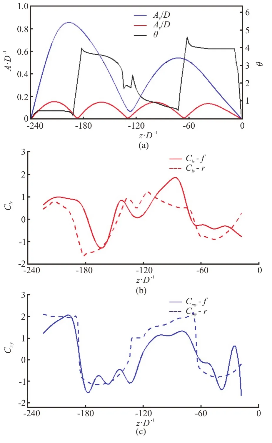
Fig.4 (Color online) Assessment of the validity of the strip theory via a comparison between fluid force distribution along the flexible cylinder (L/D=240) and the corresponding hydrodynamic coefficients acquired from the rigid cylinder combined IL and CF forced vibration[4].the flexible cylinder vibrates second mode in the CF direction and fourth mode in the IL direction(a) at Vr=12.66.The solid line in the (b) and (c) is the hydrodynamic coefficient ( Clv , Cmy ) along the flexible cylinder reconstructed from the flexible cylinder motion and the dashed line is the corresponding hydrodynamic coefficients from the rigid cylinder forced vibration with matching Ax/D ,Ay/D , Vr and θ along the model
One of the problems that the past research in the flexible cylinder VIVs seldom addressed was the inflow condition: compared with the steady uniform inflow condition widely applied in the laboratory experiment and numerical simulation, in real ocean,the current profile is unsteady[49], non-uniformly sheared[40]and can be non-orthogonal to the riser[50].
The sheared inflow condition may introduce multi-frequency vibrations, and therefore may excite multiple vibration modes.Fields observation[51]indicated that in the sheared flow condition, the flexible cylinder responded in a broad-banded frequency and traveling-wave dominated response with an averagely smaller amplitude than that in the uniform current.Later several large-scale high-mode laboratory tests[52]used rotation rig to create a well-controlled linearly sheared inflow condition.The result shows that for the large shear rate cases, the flexible cylinder still vibrates at a broad-banded single frequency but with multiple vibration modes.A similar phenomenon is observed in the simulation[40],and in addition, the lock-in region of the flexible cylinder is observed locate in the high velocity region.
Recently, Bourguet et al.[53]and Wang et al.[8]simulated a flexible cylinder in both the linearly and non-linearly sheared flow at differentRe.The results demonstrate different vibration responses[54]between the two sheared inflow conditions: in the linearly sheared flow, time-varying mono-frequency induces the multi-modal response, while in the exponentially sheared flow, multiple frequencies are found coexisting at the same time and the same location[8,55].At the same time, similar to the uniform inflow,θplays an important role in affecting the energy transfer between the fluid and the structure for the flexible cylinder in the sheared flow[54].Furthermore, the CFD simulated wake behind the oscillating flexible cylinder helps to shed light on the underlying mechanism of several phenomena.Figure 5 demonstrates that in the uniform flow (a), parallel vortex shedding in span-wise cell separated by the IL nodes can be observed[16], while in the exponentially sheared flow (b), vortices shed obliquely along the model span[54].
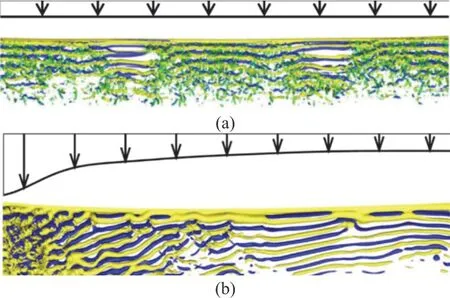
Fig.5 (Color online) Instantaneous iso-surfaces of span-wise vorticity downstream of the cylinder: (a) Parallel vortex shedding in span-wise cell separated by the IL nodes can be observed behind uniform cylinder in the uniform current from Fan et al.[4], (b) Span-wise oblique vortex shedding can be observed behind uniform cylinder in the exponentially sheared flow from Bourguet et al.[55]
Due to the riser catenary and lazy wavy configurations[56], the inflow can be non-orthogonal to the riser, questions hence are raised what the effect of spanwise flow velocity is to riser VIVs and whether the independence principle can be applied[55].Several experimental[57-59]and numerical[60]studies on the VIV characters of an inclined flexible cylinder show that the independence principle is valid for the small yaw angle but not for the large yaw angle due to the strong oblique vortex shedding.In addition, Zhu et al.[61-64]experimentally and numerically studied a curved flexible cylinder non-orthogonally placed in a sheared flow, and revealed complicated response flexible cylinder VIV under such inflow conditions.
Section summary: The recent studies successfully revealed the complex behavior and its underlying mechanism of the isolated rigid and flexible cylinder in the uniform form, and established a mapping between the three fundamental models of (1) the elastically mounted rigid cylinder, (2) the rigid cylinder forced vibration and (3) the flexible cylinder free vibration in the uniform flow.Yet some of the preliminary results of the recent researches show that many more unexplored phenomena may exist for the single flexible cylinder VIVs when the inflow condition is not uniform, steady and orthogonal.In addition, questions may raise whether the strip theory assumption still applies that a rigid cylinder forced vibration can be used to predict the hydrodynamic force distribution along the flexible cylinder span when the structure undergoes broad-banded, multiplefrequency, unsteady, and traveling-wave-dominated vibrations.
2.FIV and hydrodynamic interference of multiple cylinders
In the offshore engineering, many FIV problems involve the configurations consisting of two or more cylinders, such as arrays of riser tubes used in offshore drilling and production platforms.When one cylinder is placed in the wake of other cylinders, the occurrence of hydrodynamic interference among the cylinders will result in different structural dynamic responses and flow structures compared with those of an isolated one.In this section, we provide an outline of these concepts and phenomena generic to the FSI of multiple cylinders and pay a special attention to the flow interference of stationary cylinder wake, a wake-induced vibration of the downstream cylinder and FIV interference between free vibrating cylinders.
2.1 Flow interference of stationary cylinders
For the flow past the stationary multiple cylinders, the flow patterns become more complicated and different from those of an isolated cylinder due to the flow interference between cylinders.The different separation distance between cylinders, the orientation of incident flow with respect to the cylinder (covering the tandem, side-by-side and staggered arrangements)as well as Reynolds number produce various flow structures.Based on the flow structures developed in the cylinder gap and fluid morphology behind the cylinder, the flow interference of two cylinders has been categorized into several regimes.Figure 6 shows a visualization map of flow around two stationary cylinders with different separation and arrangement collected from several literatures[65-68].Based on the gap flow structure, Zdravkovich[66]classified the flow interference into four regions: (1) the proximity interference, (2) the proximity-wake interference, (3)the wake interference, and (4) no interference.
The proximity interference occurs for the sideby-side arrangement.This regime is characterized by the interaction between the shear layers of oppositesign vorticity developed behind two cylinders.Depending on the gap spacing, three different wake patterns are formed: the absence of gap flow of regime(a), the biased gap flow of regime (b) and the symmetric gap flow of regime (c)[68].
The proximity-wake interference takes place when the cylinders are arranged in tandem or slightly staggered with a small distance.This regime is by a reattachment of shear layers of same-sign vorticity from two bodies.With the increase of gap spacing, the gap flow exhibits three distinct behaviors, as the absence of gap flow (d), the quasi-steady recirculation(e) and the intermittent recirculation (f)[67].
The wake interference occurs when the tandem spacing increases beyond a critical distance.In this regime, the shear layers of the upstream cylinder fully roll up and resulting in an alternate vortex shedding in the gap.The upstream wake vortices impinge on the downstream cylinder and interact with the downstream vortex shedding (g)[67].
When the spacing of the two staggered cylinders becomes larger than a critical value, based on the orientation of the cylinders as well, no interference between the two cylinders can happen.In other words,the structural and flow responses of the two cylinders are similar to those of the single cylinder in the uniform inflow (h).
In addition to the categorization by Zdravkovich,alternative classification of the flow patterns around two stationary cylinders can be found in the work of Sumner et al.[69], Hu and Zhou[70], Alam and Meyer[71]and Zhou and Alam[72]
2.2 WIVs of the downstream cylinder in tandem with a stationary cylinder
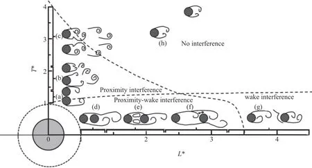
Fig.6 Flow interference classification and wake pattern visualization based on the literatures[66-68].(a) Single street, (b) Biased gap flow, (c) Symmetric vortex street, (d) Over reattachment, (e) Quasi-steady reattachment, (f) Intermittent reattachment,(g) Phase-coupled vortex shedding, (h) Independent vortex shedding as isolated cylinders
When the cylinder placed in the wake is allowed to move, its dynamic response is found to be significantly different from the typical VIV of the isolated cylinder.Such a phenomenon is named as the wakeinduced vibration (WIV).A typical WIV response is characterized by a build-up of the oscillation amplitude persisting to high reduced velocities[73-78], as shown in Fig.7(a).Moreover, unlike the lock-in response of typical VIV, WIV response frequency is not locked to a specific value close to the structural natural frequency, but linearly increases with the reduced velocity[76].The fluid force acting on the downstream cylinder is dominated by two frequency components: one corresponding to the oscillation frequency and the other associated with the upstream vortex-shedding frequency[75-76].With the increase of tandem spacing (x0/D), the WIV amplitude and synchronization region is reduced until the tandem separation beyond 20 diameters where the downstream response resembles that of a single cylinder[74,76].Depending on the mass ratio and tandem separation[73,78],the downstream cylinder can be excited into the VIV and WIV response in different specific range of reduced velocities.Much fewer experiment and simulation have been conducted on the combined-IL-and-CF free vibration of the downstream cylinder, but some preliminary result[79]show that the WIV response of the 2DOF vibration qualitatively resembles that of the CF-only vibration.Due to large amplitude response at higher reduced velocities, there are studies also refer to WIV as a wake-induced galloping (WIG)phenomenon[73,75,78].But one should distinguish this response from the galloping of non-circular bluff bodies which involves a fluid- dynamic instability.Because it is found that the upstream cylinder wake will induce a restoring lift force on the downstream cylinder and helps the oscillating cylinder return to its equilibrium point, suggesting a wake-displacement stability[80].A further study of Assi et al.[76]reveals that WIV is a result of the interactions of the structure with the vortices from the upstream wake, still a type of vortex-induced mechanism.
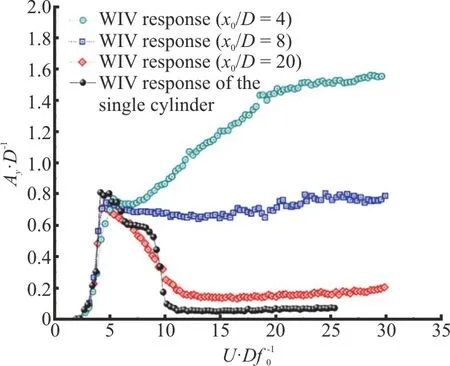
Fig.7(a) (Color online) WIV response amplitude of the downstream cylinder for various separations[76]
The characteristic response of WIV has led to many studies with the prediction of it.Assi et al.[77]introduced a concept of “wake stiffness” to model the restoring lift force acting on the downstream cylinder.Based on a quasi-static assumption, the wake stiffness is evaluated from the steady lift force acting on a static downstream cylinder.Some important characters of WIV, such as amplitude and frequency response are well predicted by this model.In order to further quantify the dynamic characters of WIV with detailed hydrodynamic coefficients, the first comprehensive forced vibration experiment on the cylinder placed in tandem downstream of a stationary cylinder has been carried out by Lin et al.[81].With a comparison between the displacement response of the downstream cylinder free-vibration with zero damping and the contour line of zeroClv(considerably different from that of the isolated cylinder case) from the forced vibration experiment, shown in Fig.7(b),the research concluded that the forced vibration can be used to map the hydrodynamic properties of WIV, and hence predict the dynamic response of WIV.In addition to predicting WIV from hydrodynamic analysis, Song et al.[82]established an empirical model for the prediction of WIV frequency response based on a fitted Strouhal frequency formula.Nevertheless,a further conclusion from these works is that the understanding of the flows and responses of WIV presents a continuing challenge and there may be yet more modes of shedding and mechanisms of response to be uncovered.
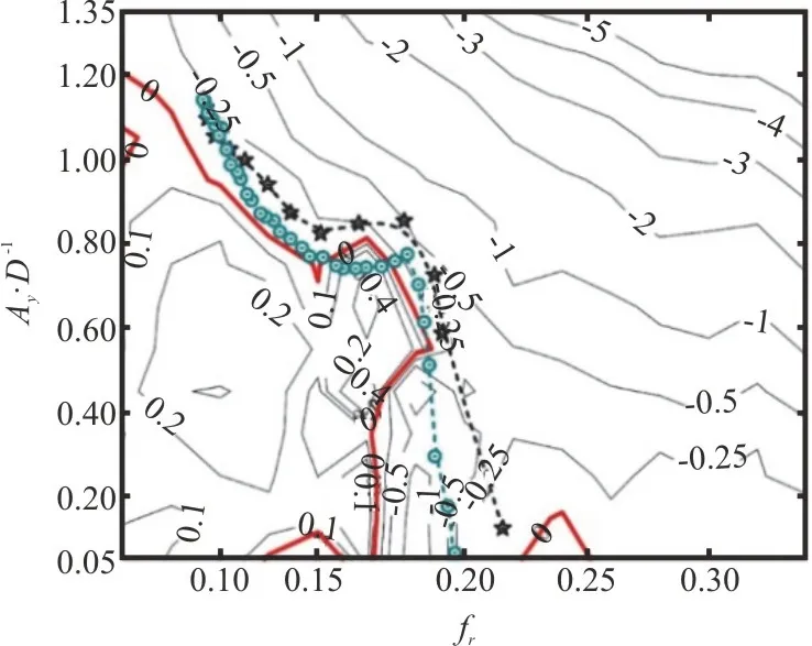
Fig.7(b) (Color online)Mapping free WIV response of Linet al.[81](☆)and Assi et al.[76] (⊙) by contour plot of Clv from forced vibration experiments
2.3 FIV and hydrodynamic interference of free vibrating cylinders
As we have seen in the studies with flow past multiple stationary cylinders, the cylinder arrangement plays an important role in shaping the properties of flow interference, as two distinct flow interference modes (proximity interference and wake interference)are identified for the two limiting arrangements(side-by-side arrangement and tandem arrangement,respectively).In this section, we bring together the studies with the FIV response of multiple free vibrating cylinders and characterize the properties of the FIV response with hydrodynamic interferences for the tandem and side-by-side arrangements, intensively.And the effect of separation spacing on the FIV interference is also included.
2.3.1 FIV and hydrodynamic interference of cylinder system in tandem arrangement
WIVs of the downstream cylinder present less than half the story of the FIV response and interference of the cylinders in tandem arrangement.If both cylinders are allowed to oscillate in the CF direction, the wake-to-structure interference not only induces the WIV response of the downstream cylinder but also may alter the FIV response of the upstream cylinder, especially when the cylinders are closely placed.As shown in Fig.6, the flow interference of the two cylinders in the tandem configuration are classified into two regimes based on the gap flow morphology: the proximity-wake interference, and the wake interference.In general, the FIV response and interference of the upstream cylinder are characterized separately for such two interference regimes as well.
With the cylinders arranged in the proximity inter ference region, the larger amplitudes of oscillation over a wider reduced velocity region is observed for the upstream cylinder compared with those of an isolated cylinder[83-86], early referred to as “proximity induced galloping”[83].LowResimulation[84]on two elastically mounted cylinder with 1.5Dtandem distance revealed that such response pattern is a result of the upstream cylinder shear layers largely modified by the motion of the close downstream cylinder in the wake.A more systemic experiment with various tandem separations performed by Kim et al.[85]again confirmed the existence of the large response amplitude for the upstream cylinder when the two cylinders are in the proximity interference range.But noticeably, cases of small or even no oscillation of the upstream cylinders have also been observed in the experiment.When two tandem cylinders become further apart and are in the wake interference region,the upstream cylinder starts to respond as an isolated cylinder with characteristics of typical VIV responses[86-89].In general, researches show that the hydrodynamic interference for the upstream cylinder only exists for small tandem separation.As a matter of fact, when the tandem separation becomes larger than a critical value about 2.5Dto 3D, the upstream cylinder response is not strongly affected by the downstream cylinder in the wake[86-89].In addition, it is noted that the downstream cylinder responds with the oscillating upstream cylinder not in the same way as the typical WIV response with the upstream cylinder fixed, as the downstream oscillation amplitude ceases to increase but drops down with the increase of reduced velocity[86-89].Apart from the separation distance, the cylinder diameter ratio[90-91,92],natural frequency ratio[93-95]and connection configuration[92,96]are all important factors that affect the tandem rigid cylinder FIV responses.For example,when a larger cylinder is placed upstream, due to the shadowing effect, the downstream cylinder at certain distance may cease to vibrate at all[90].
When the structure is flexible, for the multiple cylinder configurations, “model overlap” is shown to be an outstanding phenomenon in the FIV of multiple flexible cylinders in the tandem arrangement due to the wake-to-structure interference.The experimental studies[97-98]showed that the FIV response of the upstream riser experiences the similar vibrational model transition to that of an isolated riser.However,the downstream riser experiences a relatively indiscernible mode switching which is characterized by the multi-mode vibrations with a strong lower mode contribution, as shown in Fig.8.The upstream wake interference causes the extension of the lower modal response region of the downstream riser.The overlap of the local mode related to the typical VIV mechanism and the extended mode related to the wake interference mechanism results in a large amplitude response of the downstream cylinder during the modal transition.These phenomena agree with the wind tunnel experiments of King and Johns[99]and the flume towing experiments of Huera-Huarte et al.[100]with two flexible risers of smaller-scales.Same as the multiple rigid cylinders, the spacing between two flexible cylinders is still an important factor in characterizing the FIV structural and flow response.Huera-Huarte and Bearman[101], and Huera-Huarte and Gharib[102-103]presented the dynamic response and wake visualization for two low mass-damping flexible cylinders in tandem arrangement with near and far wake interference, respectively.They found that both two cylinders respond in a classical VIV resonance for the near wake interference with no vortex shedding in the gap.In the far wake interference regime where upstream wake vortices develop in the gap, the downstream cylinder shows a classical VIV response over the reduced velocity when an isolated cylinder is in “lock-in” and demonstrates a WIV response for the higher reduced velocities.
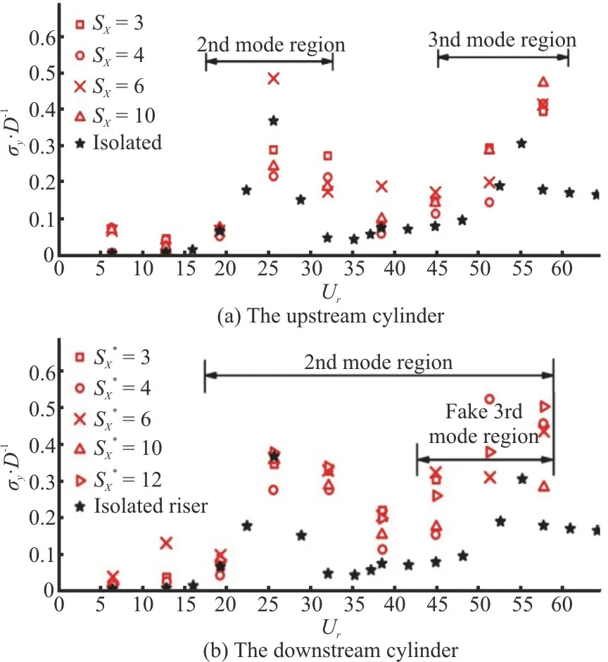
Fig.8 (Color online) FIV response amplitude of two flexible cylinders in tandem arrangement for the various separation by Liu et al.[97]
2.3.2 FIV and interference of cylinder system in sideby-side arrangement
Apart from the tandem setup, another basic configuration of the two cylinders hydrodynamic interference model is the side-by-side arrangement.In this section, we review the studies on two free vibrating cylinders in the side-by-side arrangement and discuss two concepts arisen from this problem, as(a) the FIV interference region with the side-by-side arrangement, (b) Wake-coupled vibrations associated with the proximity interference.
For tandem cylinders FIVs, the hydrodynamic interference exists for the downstream cylinder even when the separation distance reaches 20D.However,the occurrence of the interference is restricted in a much narrower spacing for the cylinders with a side-by-side arrangement.For rigid cylinders[104-106],the studies show that the flow interference is weak when the separation distance is larger than a critical value of about 3D-4D, and the “lock-in” response of the two cylinders is similar to that of an isolated cylinder.As for the side-by-side flexible cylinders[107-108], experimental results show such a critical value is found to be larger, as Xu et al.[107]observed an FIV interference for the flexible cylinders in the CF direction up to 6D, and in the IL direction up to 8D, compared to the result of an isolated cylinder towing experiment conducted with the same facility.Although different Reynolds number and structural mass ratio may cause the critical separation of the interference to variate, it is confirmed that the interference range with the side-by-side arrangement is much narrower than that with the tandem arrangement.
When the two side-by-side cylinders are in the proximity regime, wake-coupled vibration (WCV)may occur, which is characterized by the synchronization either in-phase or out-of-phase between two cylinders, depending on the reduced velocity and gap ratio[103,105].In general, the two rigid cylinders vibrate in-phase as an isolated cylinder for the very small gap ratio, and then vibration amplitude decreases with the increase of the gap ratio until a critical value when the two cylinder vibrates independently either in-phase or anti-phase[105].Such phenomenon has also been observed in the flexible cylinder experiment[103].However, even though the WCV response generally presents the in-phase or out-of-phase synchronized motion only, the flow state corresponding to the WCV response is fairly complicated.Flow visualization provided by either simulation[106,109]or experiment[110]reveals various different flow patterns that the change of the vibration response is always accompanied with distinctive wake mode switch, shown in Fig.9 for cylinders with different separation spacings.
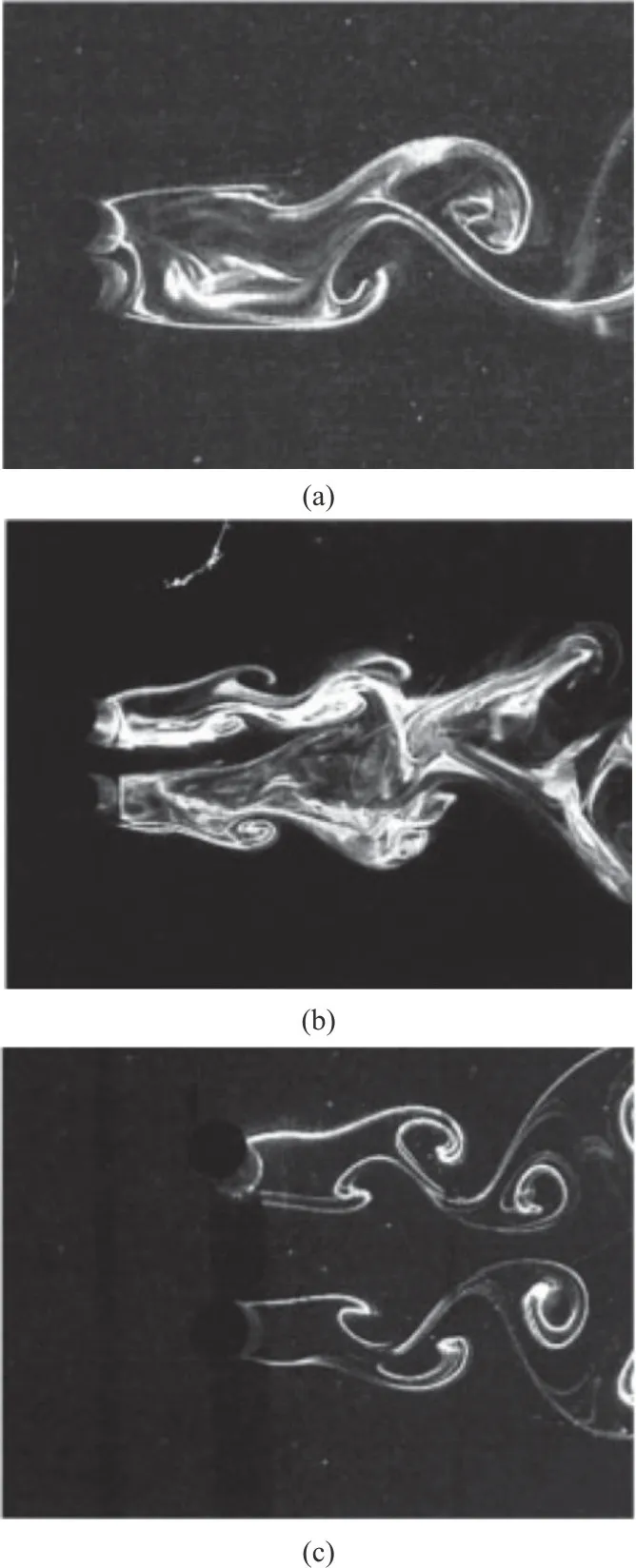
Fig.9 Laser-illuminated flow visualization of the fully coupled wake mode (a), the unbalanced wake mode (b) and the unbalanced wake mode (c) of the symmetric or antisymmetric wake mode[110]
Section summary: In a synthesis of the studies on multiple cylinders FIV, it is still a vortex induced mechanism.But due to the hydrodynamic interference,the flow state and dynamic response for the multiple cylindrical structure is more complicated and rather different from those of an isolated cylinder.The gap between cylinders, the staggered angle, the massdamping ratio, the reduced velocity, Reynolds number and the length to diameter ratio for flexible cylinder are identified as key factors for characterizing the Wake and FIV response and interference of multiple cylinders.Further understanding is needed for many more aspects, for example: (1) the effect of the combined-IL-and-CF response, the structural mass ratio and the Reynolds number on the FIV response of multiple cylinders, (2) the modeling and prediction of the wake and FIV response of an array system of cylinders, and whether the concepts and results obtained from the configuration consisting of two cylinders can be extended to the problem involving three or more cylinders[111-114], (3) in order to avoid the characteristic responses result from the interference effect, such as WIV of large amplitude,whether the traditional VIV suppression device[115-116]is still applicable or whether new type of vibration suppression devices[105,117-118]need to be developed.
3.VIV suppression and galloping for cylinders with attachment
The occurrence of VIV may result in an increase of the static loading due to the amplification of the mean drag force as well as the severe fatigue damage due to the periodic oscillation for the offshore slender structures.Therefore, in the last several decades, a large amount of the research effort has been devoted to control and suppress the VIV from happening, and different attached devices on the smooth cylinders hence were proposed and have been successfully applied in many engineering projects.However,recent studies reveal that some of the configurations do not always control the VIV, instead, may result in extremely large amplitude vibration, the gallopinglike responses.In this section, we review and discuss the researches on VIV suppression means and unwanted galloping response of circular cylinders with attached devices.
3.1 VIV suppression
Generally, VIV suppression methods can be categorized into two aspects.One is by adjusting the structural properties, such as changing bounding conditions (e.g., increasing top tension), increasing structural rigidity and damping.The other is by directly controlling the wake behind the bluff bodies,for instance, suppressing the vortex generation,reducing the vortex shedding strength and changing the vortex shedding frequencies.
For VIV suppression devices, they may be further divided into either active or passive control ones[119].Active devices need external energy input,which can be costly and impractical to use in the offshore systems.Meanwhile, passive devices do not require any energy input, and therefore, they are used widely in the ocean, wind and civil engineering.Herein we focus on the passive devices, some of them are shown in Fig.10, and the most popular ones include helical strakes, fairings and splitter plates.
To begin with, to demonstrate the overall VIV suppression performance of the three common devices,we gather the data of the maximum mean drag coefficientCdand maximum VIV CF response amplitudeAy/Dbased on the existing published results, and group them separately for helical strakes,fairings and splitter plates in Fig.11 (The source of the data are listed in Appendix.) Note herein those data of large amplitude vibration like galloping are not included, and will be further discussed in Section 3.2.
As we know, the maximum VIV amplitudeAy/Dis about 1.0 in one degree-of-freedom (1DOF)or about 1.5 in 2DOF for a single cylinder.From Fig.11, we find that fairings (region II) and splitter plates(region III) can well suppress the vibration and reduce the drag as well under certain design conditions.In detail, most fairings have the best performance in reducing the drag force, while the helical strakes(region I) can reduce the VIV amplitude at the cost of an increased drag force.It is also deserve noting that,fairings or splitter plates may induce galloping oscillation with unwanted large amplitudes under certain conditions.So all these suppression devices have both advantages and disadvantages, and their design and application should be carefully studied.
3.1.1 Helical strake
The helical strake is one of the earliest invented and most frequently used device[120], and such devices were firstly applied to chimneys, towers, etc.to prevent structure from vibrating in the strong wind.In the recent decades, the strakes are widely used for the VIV suppression on marine risers.

Fig.10 Additional devices for suppression of VIV: (a) Helical strake, (b) Streamlined fairing, (c) Single splitter plate, (d) Dual splitter plates, (e) Auxiliary control rods, (f) Bump, (g) Wave cylinder, (h) Travelling wave wall
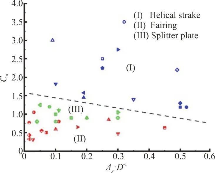
Fig.11 (Color online) Effectiveness of the VIV suppression devices: results of maximum mean drag coefficient C d versus maximum response amplitude Ay/D(The corresponding values of Ur or Re may be different for a same problem) for attaching stakes (I:blue), fairings (II: red) and splitter plates (III: green).Overall, it is found that strakes induce a larger drag and fairings can achieve maximum drag force reduction
The design of the helical strake can be characterized by five main parameters: number of start screw heads, strake pitch, strake height, strake crosssection shape and strake coverage[121-122], and the main research findings can be summarized as follows:
(1) No significant difference exists in suppression efficiency between 3-start screw head and 4- start screw head strakes, butCdwill increase as the start number increases[123].
(2) The strake pitch has less impact on the suppression efficiency[121-122,124-125], and the change on pitch of strakes affects the occurrence of lock-in region and prevents the frequency from switching into higher mode[125].
(3) The suppression efficiency of the helical strake was found to be sensitive to pitch-to-height-ratio, and in addition, the increase of the height improves the suppression efficiency of helical strakes[121,124,126-127].
(4) The influences of the different cross-section shapes of helical strakes are different but moderate[122,128].
(5) For the flexible cylinder VIV, the suppression efficiency of helical strakes increases significantly as the coverage density increases[121,124,126,129].
(6) Several researches report that the most effective VIV suppression parameters were found that the ratios of height to diameter and pitch to diameter are 0.15 or 0.25 and 15-17 for triple strakes[121,126,130].
After decades of researches and engineering applications, the helical strakes are proved to be effective tools in reducing riser VIVs.Their mechanism and effects on VIV suppression of marine risers can be summarized as follows:
(1) Helical strakes can suppress VIV very effectively at a wide range ofReandVr, but the effectiveness of helical strakes reduces as the reduced velocity increases[131].
(2) Helical strakes can narrow or even eliminate the cylinder lock-in region of amplitudes res ponse[122, 125, 132-133].
(3) Helical strakes can destroy regular vortex shedding in the stream wise direction and prevent the vortex structure from becoming correlated in the span wise direction and elongate the formation length of wake[132-135], as shown in Fig.12[132]demonstrating the flow visualization for both cylinders.
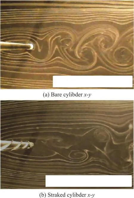
Fig.12 (Color online) Flow visualization of the bare and straked cylinder wakes on different planes[132]
(4) Helical strakes increase the mean drag coefficientCd[135-137], which is found to be independent ofRe[138]and result in a non-zero mean lift coefficientCl[137].
(5) Helical strakes can change the high order harmonics and multi-mode response to a single mode or at least fewer mode response with lower orders[139].
We need to point here that, as mentioned above,the helical strake was originally designed and deployed in the civil and wind engineering, where structural mass-damping ratio (m*)ζcan be very large.It was found via the wind tunnel experiments[122]that with a helical strake ofP/D=5,h/D=0.14 and “D”-type cross-section (m*ζ=2-3.4), the rigid cylinder VIV can be almost fully suppressed, shown in Fig.13.However, the offshore structures have a typical low mass-damping ratios (m*ζ=0.01-1).As the VIV response of the different mass-to-damping ratio is drastically different, therefore, still a lot of work needs to be done to understand the optimal design and suppression efficiency of helical strakes on VIV of the low mass-damping ratio system.

Fig.13 (Color online) Amplitude response of cylinder with different pitches of “D”-type strakes[122]
In summary, helical strakes are very effective in reducing the VIV response of cylindrical structures,however, this reduction in vibration amplitude also accompanies with drag increasing due to the large wake deficit behind the oscillating structure.Such increased drag coefficient may be undesirable in certain operating conditions, hence it is necessary to comprehensively consider various factors based on the suitable engineering requirements and conditions when selecting and designing strakes.
3.1.2 Fairing
Fairing has been another classical and popular device used to suppress vortex shedding and VIV for marine risers since the late 1970s[140].Fairing works by alleviating the adverse pressure gradient on the downstream side of the body, reducing the possibility of separation and eliminating the formation of large scale correlated vortex structures in the wake of the body.As a result, fairings are capable of effectively suppressing VIV while obtaining a substantial reduction in drag, especially for the fairings with streamlined cross-sections.
In the 1980s and 1990s, many tests found that the designed short and rotatable fairings can be very effective in suppressing VIV at high, even at subcritical or supercritical Reynolds number[141-142].By applying ultra-short fairings, the suppression will be less influenced by the variation of the attack angle and require less material as compared with longer fairings.During recent ten years, via experiments and numerical simulation, different design variations of fairing have been proposed and investigated carefully.For example, Ramamurti et al.[143]numerically studied the FIV response of a cylinder with a separated half of fairing structure, and demonstrated that this structure would effectively reduce the VIV amplitude of cylinder.Coakley and Knutson[144]developed inflatable dome-like fairing made of elastic plastic sheets.This membrane structure can apperceive the fluid pressure through the exchange of internal and external surface fluids in order to maintain a“near-optimal” streamline body for various incoming flow, and therefore, control the vibration while keeping a low drag.Furthermore, Wang et al.[145]designed a water-drop-shape fairing, and simulated cylinder response with such a fairing attached with a finite-volume total variation diminishing (TVD)approach based upon the elemental velocity vector transformation (EVVT) method.The result show thatCdcan be reduced up to about 10%-31% and the RMS lift coefficient can be reduced up to 30%-99% for all given faired systems.Wang and Gu[146]invented a rotatable fish-tail fairing to suppress VIV of riser.In a wind tunnel experiment, Liang and Wang[147]showed that this kind of devices can very effectively reduce both drag and vibration, with the drag coefficient reducing above 20% and the vibration amplitude reducing over 95% at a proper fish-tail length size.
Inevitably, fairings may change the geometrical symmetries of a circular cylinder, and new phenomena may take place.In a water tunnel experiment, it was found that a free-to-rotate short-tail fairing (with length of 0.5D) with low friction cannot get a stable position about the center of the cylinder, instead it oscillates from side to side as the cylinder responds[148].In a wind tunnel experiment, a free-to-rotate fairing may rotate around an off-axis deviated from the centerline of the wake and forms an equilibrium angle[149].This implies that there is a torque forcing the whole structure deviation to a new equilibrium location due to the fluid attaching on one side of the fairing.
In summary, fairing can effectively suppress the VIV while reducing the drag, however it has to be aligned with the flow direction when structures can be free to vibrate.Therefore, the installed fairings must be allowed to rotate freely, otherwise it may cause severe problems such as galloping.The asymmetry in the streamlines around the misaligned fairing may increase force and moment as the structure vibrates,and result in large amplitude vibrations of galloping with catastrophic failure.
3.1.3 Splitter plate
Splitter plate is another device that has been studied and deployed for flow control and VIV suppression of circular cylinders.The research initially mainly focused on the context of the bluff body wake control[150-153].In these investigations,experiments or numerical simulations were performed to study the flow patterns around a stationary cylinder with a rigid splitter plate fixed behind, and it was found that a rigid splitter plate can stabilize the near wake and suppress vortex shedding.In addition, the drag coefficient and Strouhal number vary with the splitter plate length due to modifications in the near-wake flow patterns for short splitter plates, such asL<5D.But for long splitter plates (L>5D),vortex shedding can be eliminated completely and the drag coefficient does not vary with the splitter plate length.If the splitter plate is free to rotate around the cylinder, it was found that the splitter plates will rotate to an off-axis equilibrium angle rather than align themselves with free stream due to the integrated effect of the pressure difference along the sides of the splitter plates.The mean pressures in the wake near the cylinder are higher than that of the bare cylinder.The drag coefficients and the lift coefficients are less than the corresponding bare cylinder, with a reduction up to about 30% and 90%, respectively[153].
If a rigid cylinder placed in the uniform flow is free to move, there exists a limited number of studies.The experimental results showed allowed-to-rotate rigid splitter plates with adequate rotary stiffness[154]and flexible splitter plate[155]could be used for suppressing rigid cylinder VIVs.In addition,Huera-Huarte[156]experimentally demonstrated the effectiveness of the splitter plate for flexible cylinder VIV suppression using a uniform model with 45% coverage of the splitter plates.
We need to notice that unlike the well-controlled laboratory settings, the inflow direction e.g., the current of ocean flow and the atmospheric wind come from all directions.Thus, a flow control device is preferably adaptive to the different flow directions.As a matter of fact, various plate/cylinder configurations start to draw more research attention and be explored,such as the omni-directional splitter plate that the entire cylinder/splitter plate body can freely rotate around the cylinderʼs axis[157]and hinged-rigid splitter plate that can rotate around the hinge at the base of the cylinder rather than the cylinder axis[158].
In general, similar to fairings, splitter plates can be effective tools to prevent cylinder VIVs from happening and maintain a small drag force, but special attention need to be paid galloping instabilities under some conditions, as will be discussed in Section 3.2.
3.1.4 Other VIV suppression devices
In addition to the traditional strakes, fairings and splitter plates, scientists and engineers have proposed several other VIV suppression devices, for example,bumps[133], travelling wave wall[159], etc..These new design explores the rich nature of the fluid mechanics.For example, the simulation on a cylinder with travelling wave wall at low Reynolds number is shown to significantly suppress both the CF and IL vibration of the cylinder[159].
In addition, ideas of using small control rods placed around a main cylinder[119]has been an important research direction, as it obtains both scientific complexity and practical significance in engineering applications.For example, a real drilling riser system contains a main pipe with several auxiliary pipes (choke and kill, chemical, hydraulic,pressurized pipes, etc.) serving various functional purpose (not originally designed for VIV suppression).These small cylinders can alter the fluid momentum in the wake of the large cylinder and reduce flow separation under the right placement conditions, and therefore have the potential to suppress VIV from happening.Figure 14 demonstrate that compared with the bare cylinder, the cylinder with auxiliary control rods experiences lower force[160]and is found to have a small amplitude when it is free to move[161].Furthermore, studies with small control rods, showing flow control mechanism and VIV suppression efficiency under different rods number, gap between rods and main cylinder, incoming angles, rotating control rods, etc.can be found in the recent studies[162-169].Generally, more number of small rods benefits to flow control and VIV suppression.
In a short summary, in the past, though the auxiliary pipes of drilling riser were not considered to control flow or VIV, the above researches showed that they have the potential to control the flow around the main cylinder and suppress VIV from happening, so how to further design the geometries and the layout for whole riser system should be new research interest to be sought.
3.2 Galloping of circular cylinder with attached structures
The affiliation devices attached to the bluff bodies presented above, including fairing and splitter plates, have been experimentally and numerically proved to be effective passive VIV suppression devices.However, recent studies show that such two devices sometime fail to suppress the vibration, and instead, they may result in more serious galloping responses with large or even uncontrollable amplitudes due to their asymmetrical geometries relative to the incoming flow direction[154,170-174].

Fig.14 (Color online) Flow control and VIV suppression for a real drilling riser with auxiliary pipes: Main pipe’s drag coefficient (a), Lift coefficient (b), Strouhal number (c) Under static condition[160] and VIV response amplitude (d) undergoing VIV condition[161]
Typically, the classical galloping occurs for asymmetrical structures when the incoming flow velocities are above a critical value, such as ice-coated power lines[175-176], bridges with square crosssections[177-178]in a strong wind.Different from the VIV’s nature of a self-limiting amplitude, galloping is a fluid instability phenomenon with a large or even uncontrollable amplitude.The happening mechanism of galloping of rectangular cylinder can be explained by the famous Den-Hartog’s instability criterion[179]and Parkinson’s linear quasi-steady theory[180].Galloping sometimes takes place interacting with VIV.Taking the FIV problem of square cylinders as an example, the response can be classified into four types of interactions[181,173]: “no interaction” where VIV and galloping are separated,“full interaction” where the response occurs around the range of VIV and it is dominated by galloping,“partial interaction”, and “the quenching” where a response occurs at velocities lower than the vortex resonance flow speed.Nevertheless, both the galloping and the VIV may happen for the noncircular cross sections depending on the structural and flow conditions.This raises an alarm that due to reasons,such as biofouling, the attached fairings and splitter plates may lose their ability to free-to-rotate, which results in non-circular cross sections and hence increase the possibility of the galloping.As a matter of fact, in recent years, such phenomena has been observed in the offshore applications, resulting in an active research field[154,170-174,182].
To begin with, for fairings, severe galloping phenomenon is observed for the short-tail and water-drop fairings in both the experiments[170]and simulations[171-172], and some of the results can be seen in Fig.15.The study shows the galloping of the cylinder with fixed fairings occurs at higher reduced velocity[154]and is strongly attributed to the wake formation length behind the structure[171-172].In detail,at a higher reduced velocity, the wake formation length is found to decrease and the shedding vortices alternately reattach to the faired cylinder, creating lift forces in phase with the cylinder movement[171], as shown in Fig.16.The water-drop shaped and the short-tail fairings with the same length have similar galloping performances but in different reduced velocity ranges.In addition, in some cases galloping is prominent, the vortex reattachment and the vortex shedding are found to coexist at the same time[172].Based on the studies, to avoid possible severe galloping oscillation of the fixed fairing devices,fairings with short characteristic lengths are recommended in the design of such devices.
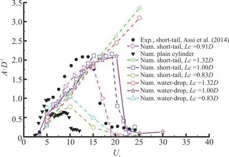
Fig.15 (Color online) Galloping response of circular cylinder fitted with different shapes of fairings[172]

Fig.16 (Color online) Comparison of the vorticity fields from the experiment[170] and the simulation.(a) Transient vorticity fields from experiment, (b) Transient vorticity from simulation, (c) Time-averaged vorticity from simulation[171]
As for the cylinder with splitter plates, early free-vibration experiments on the cylinder with attached rigid splitter plates showed that the galloping occurs at higher reduced velocities only with the splitter plate that the length is shorted than about 3Das displayed in Fig.17[182].However, recent wind tunnel experiment[163]on cylinder with splitter plate of various length observe large amplitude response even for splitter plate length of 5D, shown in Fig.18(a),indicating that structural mass ratio may also be an important factor determining the galloping response.In their experiment, four kinds of response characteristics have been observed for a circular cylinder with detached splitter plates: VIV, which lies in a discrete range of wind velocity (L/D=0.4, 0.5),the interaction between galloping and VIV (L/D=1,1.5), a combination of the velocity-restricted excitation and interaction of VIV and galloping,where there exists separate branches in the response(L/D=2, 2.5 and 3), a combination of the velocity-restricted excitation and pure classical galloping (L/D=4, 5)[173].If the splitter plate is flexible[174], the cylinder is then found to vibrate at a smaller amplitude than that of the cylinder with the rigid splitter plate[173], and it was reported when the flexible splitter plater length is smaller than 1D[155,174],VIV can be effectively controlled, shown in Fig.18(b).In addition, as for free-to-rotate rigid splitter plates,the level of torsional friction plays a key role in holding the devices in a stable position.When the torsional friction is below a critical value, the galloping of the cylinder may occur[154].Generally, for the splitter plate, when it is designed properly with adequate torsional friction and appropriate length, it can be used to significantly suppress cylinder VIV while helps to remain a low drag force.On the other hand, without cautious study, the deployed splitter plate may result in catastrophic galloping of unwanted and uncontrollable large vibration amplitude.
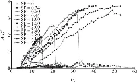
Fig.17 Amplitude response plots of splitter plate ratios L/D=0 - 4 [182].Galloping-type response halts abruptly at higher reduced velocity at L/D=0.34 - 0.5
Section summary: When designed and deployed properly, helical strakes, fairings and split plates can be effective VIV suppression devices, but without precaution, galloping of unwanted large amplitude may occur for the cylinder with fairing and splitter plates.Therefore, a lot more research effort is still required to understand the physics behind these phenomena.In addition, new VIV suppression devices need to be explored for the risers, pipes, columns,cables in single or groups (multiple cylinders hydrodynamic interference happens) layout.The following questions may be raised in designing new VIV suppression devices: Can the device reduce the IL drag force and suppress the CF vibration response simultaneously? Can the device adapt to the varying incoming flow directions? Will galloping be excited due to the device deployment? What is the proper setup of the device on flexible slender structures, e.g.,what is the optimum coverage on the structure?
4.Conclusion remarks, comments and future research prospects
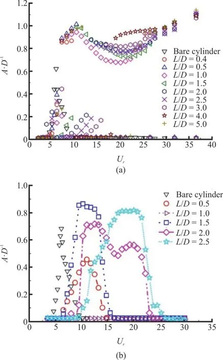
Fig.18 (Color online) Response of a circular cylinder with splitter plates at different length ratio: (a) Detached rigid splitter plates, strong vibrations happened[173],(b) Flexible splitter plates (L/D=0.5 - 2.5) , the vibration was almost completely suppressed at L/D=1 [174]
FIV of offshore bluff bodies is an intrinsically non-linear fluid-structure coupled motion with multidegrees of freedom.Due to its rich physical phenomena and important engineering applications,FIV has been the center of the FSI research for decades.In this review, we do not specially discuss the specific research methods but focus on many fundamental results and their practical applications from the recent studies, including VIVs and WIVs of rigid and flexible single and multiple cylinders, and VIV suppression and unwanted galloping of cylinders with attachments.Needlessly to say, the experimental method is still an irreplaceable method in the future,which provides reliable, direct, and observable results to find new phenomena, explore and explain the mechanisms with water flume, towing tank, water and wind tunnel, etc.at a model scale.In the meantime,with the increasing computation capacity, the CFD method for FSI modeling will become a more important and reliable tool to study large scale offshore FIV problem while providing a detailed wake visualization for physical understanding.Apart, for the FIV research for offshore bluff body applications,there is still a lack of full scale FIV data in various flow conditions for new phenomenon discoveries, a need of new tools capable of finding the hidden physics of the fluid properties and systemically exploring FIV’s large input parametric space, and a robust method of transferring the laboratory measurement and simulation to real-world applications and improve riser and pipeline monitoring and safe operation.
CFD now is the most important and challenging subject of fundamental researches of FSI, which can be applied with many methods, for instance, using high resolution numerical technique for computational accuracy, using different model to consider Reynolds number influence.Generally speaking, the more accurate for a problem to be solved, the higher the computation cost is.Laminar flow is still a fundamental, but most real offshore problems require high Reynolds number and turbulence flow modelling.Direct numerical simulation (DNS) can be considered the most accurate method, however, it should require too many fine meshes and take too much computer resources, and it can only solve low or lower Reynolds number in the present software and hardware conditions.RANS turbulence model is the popular means used by most researchers to capture the turbulence average physical parameters due to its middle computational cost and relative good accuracy.DVM is an efficient and simplified meshless numerical method which has the least computational cost comparing above other models.It discretizes the continuously distributed vorticity flied of fluid into a series of vortex elements and solves the vorticity transport equation to trace the motion of these vortex elements.DVM is a prospective method because of its low computational cost and meshless dealing,however, which is 2-D method, for 3-D or large length to diameter ratio structures, a strip theory should be considered.How to deal with the relation between“strips” is also a key point.We believe, the high-resolution or high fidelity CFD method for full RANS and high efficient CFD method for simplified RANS will play more important role on the simulation of FIV for large length to diameter risers.By the way,a kind of vortex identification method, newly proposed omega method in fluid mechanics especially hydrodynamics for revealing the underlying vortical structures is being introduced and deeply researched and extended with its applications in recent years[183].As vortices must be the key analysis contents in the modeling of FIV of offshore structure, we think this vortex identification method may be applied to reveal the vortex structures in future numerical simulation analysis.
Limited by the experimental and simulation capabilities, most of the past research focused on the single rigid cylinder or flexible cylinder of small aspect ratios (L/D≤O(100)) in the uniform flow at small and moderate Reynolds number(Re~O(10000)), which is significantly different from the conditions where the offshore bluff bodies operate in.The study[184]shows that the Reynolds number plays a non-trivial role in determining the maximum CF amplitude of a rigid cylinder free to vibrate only in the CF direction at a subcriticalReregion from 1 000 to 20 000.Therefore, questions may be raised on how the cylinder will respond at higherRe, such as in the critical and super-critical region; whether the Reynolds number will have a similar effect on the rigid cylinder combined-IL-and-CF vibration, compared to the CF-only vibration.Whether and how the characters of rigid cylinder VIVs can be applied to the flexible cylinder VIVs at different Reynolds number in the uniform or sheared flow? Whether and how the lesson we learned from the single cylinder can be applied to the multiple rigid and flexible cylinders? Whether and how the lesson we learned from the model scale of cylinders can be applied to the real scale large diameter and length of cylinders? These questions remain unanswered and are potentially addressed soon with the advancement of the new experimental and simulation tools.
One of the major objectives of the FIV study is to understand how to migrate or suppress the structural vibration with proper attachments in the engineering practice.We believe that the traditional VIV suppression method or devices: the helical strakes, rotational splitter plates, rotational fairings,etc.have obvious VIV suppression abilities, and should be continuously studied in order to find the best structural types, parameters and conditions to control VIVs and even WIVs in offshore structures.In recent years, galloping or, more accurately,galloping-like vibration starts to attract increasing attentions in the offshore engineering, due to the fact that the deployment of the attached rigid fairings and splitter plates may form an asymmetric geometry and result in a strong galloping-like response.Such a vibration phenomenon has a more complicated fluid-structure coupling mechanism, as it may be excited independently or along with a VIV-galloping interaction.Furthermore, the multiple cylinders system, such as arrays of risers used in the TLP platform, may encounter WIV with different mechanism from the VIV of an isolated cylinder is also an important problem in ocean engineering.Whether the traditional suppression methods have good effects or what extend of effects are there for the suppression of vibrations in the system of multiple cylinders? Therefore, it calls for a further study and a more careful consideration on the rigid fairing and splitter plate deployments, and the use of the VIV suppression devices on the multiple cylinders in the field.The good experimental and numerical modelling and prediction ability of the galloping oscillation or WIV response for the complicated structures is expected to be well addressed since the safety insurances of structures will related to the scientific and accurate prediction, understanding, and design.
In recent years, we see a leap in the development of the artificial intelligence and its application in various fields of computer science.Now machine learning starts to change the landscape of fluid mechanics research, and presents us with a rich number of effective tools to extract the information from data and helps to discover the underlying and sometime hidden physics in the problem of fluid mechanics[185].Some preliminary researches include FIV feature extraction using physics-informed neural network[186]and Gaussian-process-regression-endorsed intelligent towing tank for rigid bluff body hydrodynamic database construction[187].These successful cases have demonstrated a potential paradigm shift in FIV research and provided possibilities of systematically exploring and mapping the fundamental features of FIVs as a complex function of many input parameters.
Last but not least, we like to point out that the engineering problem inspired laboratory research need to later be transferred into the industrial application,and there still lays great challenges but research opportunities in how to apply the knowledge we learned in experiments and simulations to the design and operation of the offshore bluff bodies.For example, in real-world applications, offshore risers are often deployed in oil-gas exploration and production for more than three decades.During this long time period, riser response statistics may vary significantly due to the variation of the external loadings (change of the wave and current statistics) and alternation of the structural properties (biofouling and system aging),which leads to challenges in long-term riser monitoring.Ideas of digital twin[188]that leverages information between offline models (experiments,high-fidelity simulations, reduced-order modeling)and online sensor inquiry are expected to compensate un-modeled physics and provide accurate riser response prediction over the entire offshore riser life span.
Acknowledgements
The authors would like to acknowledge Prof.Lian-di Zhou for his good suggestions to improve the paper.
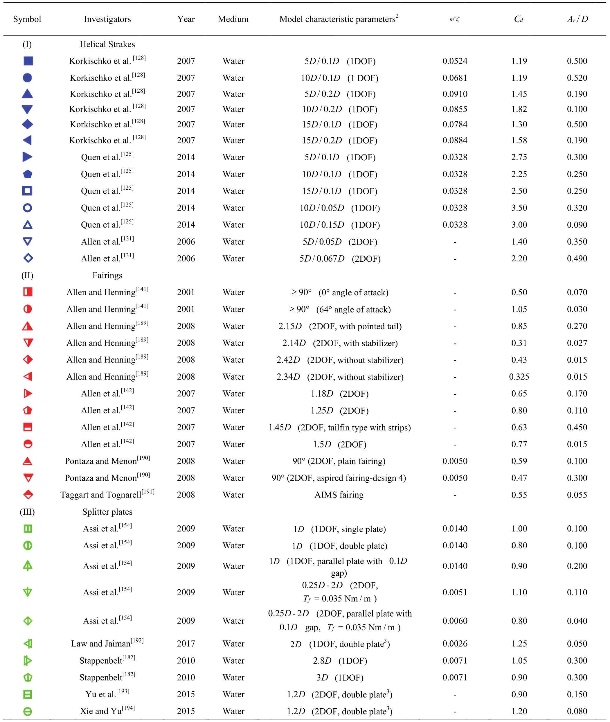
Appendix (Color online) Cd and Ay/D data from the relative publishes1
杂志排行
水动力学研究与进展 B辑的其它文章
- Principal coordinates and principal velocity gradient tensor decomposition *
- Study on the flow structure around discontinued vertically layered vegetation in an open channel *
- Numerical study of morphological characteristics of rotational natural supercavitation by rotational supercavitating evaporator with optimized blade shape *
- Estimation of the turbulent viscous shear stress in a centrifugal rotary blood pump by the large eddy particle image velocimetry method *
- POD analysis on vortical structures in MVG wake by Liutex core line identification *
- Importance of incorporating systemic cerebroarterial hemodynamics into computational modeling of blood flow in intracranial aneurysm *
