斜井掌子面形状与倾角对隧道开挖面稳定性影响
2020-11-19安永林李佳豪赵丹岳健
安永林,李佳豪,赵丹,岳健
斜井掌子面形状与倾角对隧道开挖面稳定性影响
安永林1, 2,李佳豪1, 2,赵丹3, 4,岳健2
(1. 湖南科技大学 岩土工程稳定控制与健康监测省重点实验室,湖南 湘潭 411201;2. 湖南科技大学 土木工程学院,湖南 湘潭 411201;3. 长沙市轨道交通集团有限公司,湖南 长沙 410000;4. 中南大学 地球科学与信息物理学院,湖南 长沙 410075)
基于强度折减极限有限元法,建立直立形、倾斜形和曲面形3种掌子面形状的模型。针对不同倾角的斜井模型,研究网格多少以及局部加密自适应网格对计算结果的影响,分析掌子面安全系数与破坏形状之间的关系,并将安全系数同有限元分析作对比。研究结果表明:网格越精细,安全系数越低;曲面形掌子面的稳定系数小于直立形式的,直立形式的小于倾斜形式的;掌子面越倾斜,越稳定,类似于起到核心土的作用;掌子面底部与拱顶存在次应变集中带,隧道在纵断面上存在分区破坏;当掌子面形状为微椭圆形时,其稳定性略有提高,但随着椭圆度增大,安全系数降低,实际施工中,椭圆度不宜控制,建议有条件下可采用斜掌子面;斜井倾角越大,掌子面稳定性越低,所以大倾角斜井与大反坡隧道施工,更要采取措施控制掌子面的稳定;低黏聚力的破碎围岩,应通过注浆等措施,改善围岩力学参数,提高掌子面稳定性。
隧道工程;掌子面稳定;掌子面形状;斜井倾角
掌子面保持稳定是隧道能够安全施工的前提。相关学者做了大量研究:Davis等[1]提出了不排水情况下4种隧道破坏模式,并基于极限分析给出了支护力与稳定系数的上限解和下限解。Leca等[2]构造了砂土地层条件下隧道掌子面三维破坏模式并确定了维持掌子面稳定的最大及最小支护力。Subrin等[3-7]对该三维模式做了改进。其中Subrin破坏模式形状类似于牛角状;Mollon破坏面模式采用了空间离散化技术逐点生成,形状更为灵活。在渗流作用下,Lee等[8−10]推导了掌子面支护压力表达式,并分析了掘进速率、超前支护等的影响。Salvador 等[11]将Hoek-Brown准则应用到极限分析中。关宝树[12]对斜掌子面形式做了介绍,英国在几座铁路和公路隧道中采用倾斜的掌子面进行开挖,并取得了良好的稳定效果,表明斜掌子面有利于提高掌子面稳定性。总体来看,对掌子面自身的稳定研究较多,而对于不同掌子面形式下,掌子面的稳定性的研究还较少。本文在前期研究的基础上[13−14],进一步基于强度折减极限有限元,建立直立形、倾斜形、曲面形3种掌子面形状的模型,以及不同倾角的斜井模型,研究网格多少以及局部加密自适应网格对计算结果的影响,分析掌子面安全系数与破坏形状,并同有限元分析作对比。
1 模型的建立与分析原理
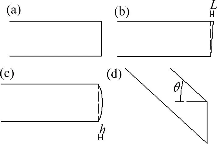
不同掌子面形式见图1,网格划分见图2,围岩参数见表1所示,本构关系为Mohr-Coulomb,模型边界为左右水平约束,底部为竖向约束,顶面为自由表面,隧道衬砌段为约束段,掌子面为自由面。注,图1(b)中,本文用表示掌子面倾斜程度,建立了4种工况: 1,2,3和4 m,值越大,表明掌子面越倾斜;图1(c)中,本文用表示曲掌子面圆弧高度,即掌子面弧度曲线中心到竖向掌子面的中心距离,建立了7种工况:0.25,0.5,0.75,1,1.5,2和2.3 m,值越大,表明掌子面弧度越大;图1(d)中,本文用表示斜井倾角,建立了7种工况:5°,10°,15°,20°,25°,30°,35°,值越大,表明斜井倾角越大,即越陡。

表1 计算力学参数

(a) 竖直掌子面;(b) 倾斜掌子面;(c) 曲形掌子面;(d) 斜井掌子面
强度折减法原理是对围岩的力学参数摩擦角与黏聚力进行折减;对于常规有限元强度折减法,本文是以不收敛作为判定依据的;对于极限分析有限元强度折减,是以强度折减到开挖面的支护力为0的相应折减系数作为安全系数。

(a) 均匀网格;(b) 局部加密网格
2 网格对计算结果影响分析
均匀网格划分的网格数对安全系数的影响见图3(a),局部加密网格数的影响见图3(b):对于均匀网格,需要更多的单元数才能达到计算的安全系数不变,而局部加密网格在相对较少的单元数下就能使得结果稳定,如局部加密网格是5 000,而均匀网格要10万个才可以。

(a) 均匀网格;(b) 局部加密网格
3 不同计算方法对比
见图4:下限法(LOW-FEM)的安全系数最低,上限有限元法(UP-FEM)在中间,而采用常规有限元(FEM -SRM)进行强度折减所得安全系数最大,上限法居中,而下限法最小,这可能与计算的准则有关;若以上限法为基准,则各方法计算误差在2%~10%之间,误差不大;用强度折减有限元获得安全系数,其计算耗时较长,后面分析斜井的稳定性,采用了上限法进行分析。

(a) 掌子面倾斜长度;(b) 掌子面圆弧高度
4 掌子面形式对掌子面稳定性影响
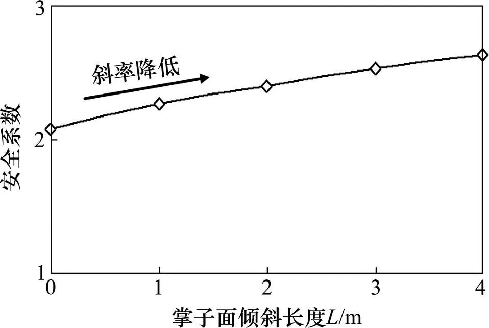
倾斜掌子面的影响见图5,曲形掌子面的影响见图6。
1) 掌子面安全系数随着掌子面倾斜长度增加而提高,但提高的斜率逐渐降低;掌子面的倾斜部分起到类似核心土或者堆载反压的作用,提高了隧道的稳定性,与文献[12]较一致。
2) 随着曲形掌子面圆弧高度的提高,掌子面稳定性提高,达到0.5 m时,达到极值,此时安全系数为2.138,然后又降低。表明:微小弯曲的掌子面形式有利于掌子面的稳定,与文献[15]一致,这可能与拱效应有关,但是提高的幅度不大;而后随着掌子面圆弧高度的增加,安全系数降低,笔者认为可能是圆弧高度大,则其中间空去部分相当于缺少了核心土的支撑,不利于掌子面的稳定。

图5 掌子面倾斜长度对安全性影响
3) 考虑到曲面掌子面弧度不好控制,建议不采用曲面掌子面;有条件下宜采用倾斜掌子面,特别对于软弱地层开挖,能较好增加掌子面的稳定性。
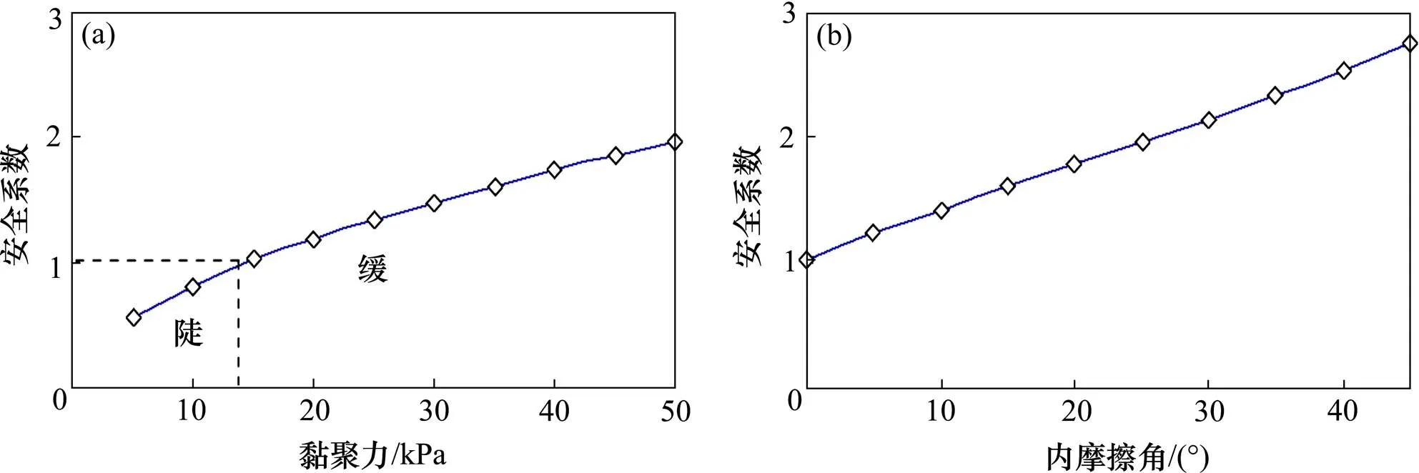
4) 本文进一步分析了抗剪强度参数黏聚力与内摩擦角对掌子面稳定性的影响,见图7,其表现规律与文献[14]一致,即随着黏聚力与内摩擦提高,掌子面稳定性提高,在低黏聚力下,稳定安全系数小于1,不稳定,也即对于破碎围岩,应通过注浆等措施,改善围岩力学参数,提高掌子面稳定性。

图6 掌子面圆弧高度对安全性影响

(a) 黏聚力影响;(b) 内摩擦角影响
5 掌子面形式对掌子面破坏形态影响
不同掌子面形式下掌子面的破坏形态见图8与图9。
1) 随着掌子面倾斜长度的增加,其塑性区面积增大,这是由于倾斜长度越大,安全系数越大,则其折减系数越大,所以折减后围岩越差,即塑性区越大;同时,倾斜长度为1 m时,塑性区在底部比较集中,而当为2~4 m时,塑性区在底部出现了次应变集中带(本文提的次应应变是相对于掌子面前方主要的剪切带而言的),次应变带的长度随着增大,而变大;这个类似于掌子面可能出现分区破裂的可能,类似于隧道环向出现分区破坏,所以,隧道分区破坏不仅出现在横断面上,在纵断面也存在分区破坏,其在空间是连续的。
2) 随着曲面掌子面圆弧高度的增加,塑性区降低,如圆弧高度为2 m时,其塑性区范围只在圆弧掌子面周边很小范围,圆弧高度为0.5时,存在明显的塑性应变集中带,对比图6,可知,2 m圆弧高度的安全系数小于0.5 m圆弧高度的安全系数,一方面折减系数少,另一方面,把较差围岩部分挖掉,并不利于围岩,其减少了类似于核心土的支撑作用,塑性区降低,但安全系数也降低。
3) 在掌子面顶部也存在次应变集中,且随着掌子面倾斜长度增大而略微增大,且曲面掌子形式下的拱顶塑性区明显小于斜面的,这可能与该出存在拐角的应力集中有关。

(a) L=1 m;(b) L=2 m;(a) L=3 m;(b) L=4 m

(a) h=0.5 m;(b) h=1 m;(c) h=2 m;(d) h=2.3 m
6 斜井倾角对掌子面稳定性影响
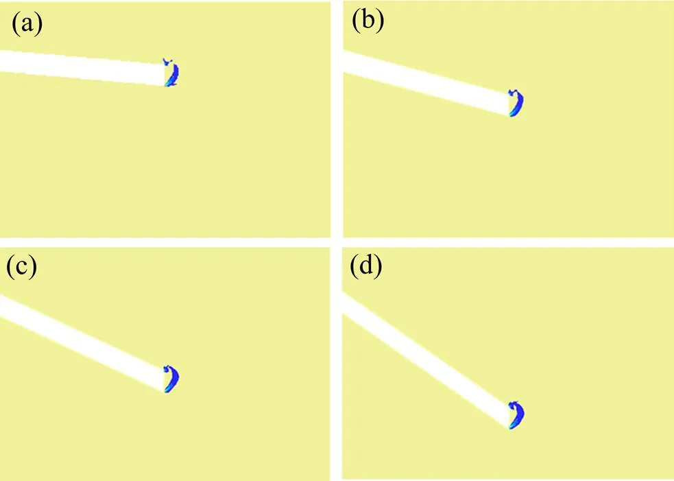
不同倾角下掌子面的安全系数见图10,破坏形态见图11:随着斜井倾角的增大,其安全系数降低,所以斜井坡度较大情况下,更应注重掌子面的稳定性,同样对于存在较大反坡施工的隧道,也应注重掌子面的稳定;塑性区形态基本类似于牛角状,这与文献[3]类似,即掌子面前方是螺旋线,掌子面上方类似三角形。

图10 斜井倾角对安全系数影响

(a) θ=5°;(b) θ=15°;(c) θ=25°;(d) θ=35°
7 结论
1) 曲面形掌子面的稳定系数小于直立形式的,直立形式的小于倾斜形式的。
2) 掌子面越倾斜,越稳定,类似于起到核心土的作用;倾斜掌子面底部出现了次应变集中带,次应变带的长度随着倾斜长度增大而变大;隧道在纵断面上存在分区破坏,其在空间连续的。
3) 掌子面微椭圆下,稳定性略有提高,但随着椭圆度增大,安全系数降低,实际施工中,椭圆度不宜控制,建议有条件下可采用斜掌子面。
4) 随着黏聚力与内摩擦提高,掌子面稳定性提高,在低黏聚力下,稳定安全系数小于1,不稳定,即对于低黏聚力破碎围岩,应通过注浆等措施,改善围岩力学参数,提高掌子面稳定性。
5) 斜井倾角越大,掌子面稳定性越低,所以大倾角斜井以及大反坡隧道施工,更要采取措施控制掌子面的稳定。
致谢
感谢中南大学地球科学与信息物理学院博士后工作站的支持和帮助。
[1] Davis E H, Gunn M J, Mair R J, et al. The stability of shallow tunnels and underground openings in cohesive material[J]. Geotechnique, 1980, 30(4): 397−416.
[2] Leca E, Dormieux L. Upper and lower bound solutions for the face stability of shallow circular tunnels in frictional material[J]. Geotechnique, 1990, 40(4): 581−606.
[3] Soubra A H. Three-dimensional face stability analysis of shallow circular tunnels[C]// International Conference on Geotechnical and Geological Engineering, 2000: 19−24.
[4] Subrin D, Wong H. Tunnel face stability in frictional material: A new 3D failure mechanism[J]. C. R. Mecanique, 2002, 330: 513−518.
[5] Mollon G, Dias D, Soubra A H. Probabilistic analysis and design of circular tunnels against face stability[J]. International Journal of Geomechanics, 2009, 9(6): 237− 249.
[6] Guilhem Mollon, Daniel Dias, Abdul-Hamid Soubra. Face stability analysis of circular tunnels driven by a pressurized shield[J]. Journal of Geotechnical and Geoenvironmental Engineering, 2010, 136(1): 215−229.
[7] Guilhem Mollon, Daniel Dias, Abdul-Hamid Soubra. Rotational failure mechanisms for the face stability analysis of tunnels driven by a pressurized shield[J]. International Journal for Numerical and Analytical Methods in Geomechanics, 2011, 35(12): 1363−1388.
[8] Lee I M, Nam S W. The study of seepage forces acting on the tunnel lining and tunnel face in shallow tunnels[J]. Tunneling and Underground Space Technology, 2001, 16(1): 31−40.
[9] Lee I M, Nam S W. Effect of tunnel advance rate on seepage forces acting on the underwater tunnel face[J]. Tunneling and Underground Space Technology, 2004, 19(3): 273−281.
[10] Lee I M, Lee J S, Nam S W. Effect of seepage force on tunnel face stability reinforced with multi-step pipe grouting[J]. Tunnelling and Underground Space Technology, 2004, 19(6): 551−565.
[11] Salvador Senent, Guilhem Mollon, Rafael Jimenez. Tunnel face stability in heavily fractured rock masses that follow the Hoek–Brown failure[J]. International Journal of Rock Mechanics and Mining Science, 2013, 60(6): 440− 451.
[12] 关宝树. 软弱围岩隧道变形及其控制技术[J]. 隧道建设, 2011, 31(1): 1−17.GUANG Baoshu. Deformation of tunnels with soft[J]. Tunnel Construction, 2011, 31(1): 1−17.
[13] 安永林, 李佳豪, 曹前, 等. 基于极限分析的进尺对隧道掌子面稳定性影响[J]. 铁道科学与工程学报, 2019, 16(2): 443−449. AN Yonglin, LI Jiahao, CAO Qian, et al. Influence of excavation footage on tunnel face stability using limit analysis[J]. Journal of Railway Science and Engineering, 2019, 16(2): 443−449.
[14] 安永林, 李佳豪, 曹前, 等.上软下硬地层隧道掌子面坍方稳定性[J]. 中国铁道科学, 2019, 40(1): 79−87. AN Yonglin, LI Jiahao, CAO Qian, et al. Analysis of tunnel face stability in soft-hard ground layers[J]. China Railway Science, 2019, 40(1): 79−87
[15] 杨晓华, 聂双成, 晏长根, 等. 变质软岩变形特征与支护技术[M]. 北京: 人民交通出版社, 2014: 76−78. YANG Xiaohua, NIE Shuangcheng, YAN Changgen, et al. Deformation characteristics and support Technology of metamorphic soft rock[M]. Beijing: China Communications Press, 2014: 76−78.
Analysis of the influence of the tunnel face shape and the inclination of the inclined shaft on the tunnel face stability
AN Yonglin1, 2, LI Jiahao2, ZHAO Dan3, 4, YUE Jian2
(1. Hunan Provincial Key Laboratory of Geotechnical Engineering for Stability Control and Health Monitoring,Hunan University of Science and Technology, Xiangtan 411201, China;2. School of Civil Engineering, Hunan University of Science and Technology, Xiangtan 411201,China; 3. Changsha Metro Group Co., Ltd., Changsha 410000, China; 4. School of Geosciences and Info-physics, Central South University, Changsha 410075, China)
Based on the strength reduction finite element method, three models of face shapes, vertical, different inclination, different ellipticity were studied, and inclined shaft models with different inclination angles were established. The influence of the number of mesh and the local encryption of adaptive mesh on the calculation results were studied. The safety factor and failure shape of the face were analyzed and compared with the limit analysis. The results show that: the finer the grids, the lower the safety factor; the coefficient of stability of a circular face is smaller than that of an vertical form, and that of an vertical form is smaller than that of an inclined form; The more inclined the face is, the more stable it is, which is similar to the role of core soil. There is a sub-strain concentration zone at the bottom and the crown of the tunnel face, and there is zonal failure in the longitudinal section of the tunnel. The stability of the face is slightly improved under the micro ellipticity, but with the ellipticity increasing, the safety factor decreases. In actual construction, the ellipticity is not suitable to be controlled, it is suggested that the inclined face can be used under certain conditions; The larger the inclination of inclined shaft is, the lower the stability of the face is. Therefore, measures should be taken to control the stability of the tunnel face in the construction of inclined shaft with large angle and large reverse slope. For broken rock with low cohesiveness, grouting and other measures should be adopted to improve the mechanical parameters of the rock and improve the tunnel face stability.
tunnel engineering; tunnel face stability; tunnel face shape; inclined angle of inclined well

U459.2
A
1672 − 7029(2020)10 − 2612 − 06
10.19713/j.cnki.43−1423/u.T20191120
2019−12−12
国家自然科学基金资助项目(51408216,51308209);湖南省学位与研究生教育教学改革研究项目;湖南科技大学研究生培养改革研究项目(J151101)
赵丹(1982–),女,湖南长沙人,博士,从事地下工程的设计与研究工作;E−mail:453933979@qq.com
(编辑 蒋学东)
