Attitude estimation method based on extended Kalman filter algorithm with 22 dimensional state vector for low-cost agricultural UAV ①
2020-07-12WuHelong吴和龙PeiXinbiaoLiJihuiGaoHuibinBaiYue
Wu Helong(吴和龙), Pei Xinbiao , Li Jihui, Gao Huibin, Bai Yue
(*Changchun Institute of Optics, Fine Mechanics and Physics, Chinese Academy of Sciences, Changchun 130033, P.R.China) (**University of Chinese Academy of Sciences, Beijing 100049, P.R.China)
Abstract
Key words: coaxial sixteen-rotor unmanned aerial vehicle (UAV), extended Kalman filter (EKF), quaternion, low-cost
0 Introduction
In recent years, multi-rotor unmanned aerial vehicles (UAVs) have received extensive attention in the field of agricultural applications. Agricultural UAV has the advantages of high operation speed, well-distributed spraying and high efficiency[1]. And precision pesticide application is an effective way to reduce pesticide residues. However, there are many technical problems in the application of agricultural UAV[2]. The first problem to be solved is lack of large load and high mobility for conventional UAV. When agricultural UAV is loaded with pesticides in work, the body generates intense vibrations. The traditional light-duty UAV cannot meet the demand of the large load of agricultural UAV, and conventional attitude estimation methods are unable to meet the need of large loads working conditions. Therefore, it is necessary to optimize the design of the structure and attitude estimation method for UAV.
Attitude measurement is one of the most important components of the UAV control system and the accuracy of the measure system has a great influence on the control performance[3]. However, for a multi-rotor UAV with the gross weight of less than 25 kg and flight time less than 30 min, using high accuracy inertial navigation system is not practical due to high cost[4], weight and space constraints. Micro electronic mechanical system (MEMS) is the high tech-electronic mechanical device with low cost compared to other high-precision mechanical measurement system[5]. Large errors in low-cost inertial sensors can cause low precision in process of attitude estimation, but low-cost inertial sensors are used to calculate the high-precision attitude angle, hence the attitude estimation method must be optimized. This study develops a low-cost flight attitude measurement system based on STM32F429 controller, attitude measure sensors MPU6000, LSM303D, HMC5883L and GPS NEO-M8N.
Attitude estimation methods for UAV have complementary filter (CPF), EKF, conjugate gradient filtering (CGF) and unscented Kalman filter (UKF)[6]. The most widely used are the CPF algorithm and the EKF algorithm. CPF algorithm can be regarded as a data fusion algorithm based on first order differential system. CPF can effectively integrate magnetometer information, GPS information with low frequency characteristics and gyroscope, accelerometer information with high frequency characteristics. The advantage of this algorithm is that it has good stability in the process of attitude estimation and it can filter out gyroscope noise and suppress drift. The EKF algorithm is a high-precision attitude estimation method and widely used in the UAV[7]. However, EKF has a disadvantage: when the linearization assumption is not established, the linearization will cause the filter to be extremely unstable, and it is easy to diverge in the attitude estimation process[8,9].
Attitude estimation method based on EKF algorithm with 22 dimensional state vector for agricultural UAV is proposed. The quaternion-based attitude estimation method can effectively reduce the amount of calculation and avoid singularity problem of Euler angle. The information from a series of different sensors is integrated by EKF. Attitude estimation process is divided into 5 processes: state prediction, error variance prediction, magnetometer data fusion, GPS/barometer data fusion and optimal estimate of error variance. The advantage of this algorithm is that by combing all available measurements, measurements with appreciable errors will be rejected, so that the UAV is less sensitive to the effects of individual sensor failure. Another advantage of this algorithm is that the accelerometer bias, gyroscope bias, body magnetic field bias and the earth’s magnetic field for UAV can be estimated. This makes it less sensitive to MEMS sensor errors than other attitude algorithms.
1 System design of agricultural UAV
1.1 Introduction of coaxial sixteen-rotor UAV platform
In order to meet the large load requirements of agricultural UAV, 8-axis multi-rotor UAV is improved by increasing the number of driving units. The structure of coaxial rotors and tilt structure of the rotor module are proposed in the laboratory, and the electric-powered multi-rotor UAV is named coaxial sixteen-rotor UAV. Coaxial sixteen-rotor UAV’s 16 motors work at the same time, causing great vibration to the inertial measurement unit[10]. In addition, during the liquid spray process, due to shaking of the liquid pesticide in the pesticide box, additional disturbance torque is caused during the flight of the UAV[11]. In order to spray precisely on farmland, accuracy of the attitude estimation of the coaxial sixteen-rotor UAV needs to be improved.
The UAV’s structure is shown in Fig.1. Eight equal-length arms are placed evenly around the center of the UAV. On the tip of each arm, there are coaxial rotors with 2 driving units. In counterclockwise direction the 8 rotors are numbered 1-8. Among them, the upper rotor of No.2, 4, 6, 8 and the lower rotor of No.1,3,5,7 rotate clockwise, while the upper rotor of No.1,3,5,7 and the lower rotor of No.2,4,6,8 rotate counterclockwise. The angle between the rotor’s shaft and the body plane isγ(0<γ<90 °), and 2 adjacent rotor’s shaft points opposite direction[12]. The navigation coordinate system and the body coordinate system are shown in Fig.2.
The coaxial sixteen-rotor UAV not only has the advantages of traditional multi-rotor UAV, but also its unique coaxial rotors and tilting structure of the rotor modules makes the anti-torque moments generated by the upper and lower rotors on one axis cancel each other. The yaw of the UAV relies on the force component of lift in the horizontal direction, unlike the traditional UAV relying on anti-torque to control yaw[13]. This structure makes the whole system more maneuverable.
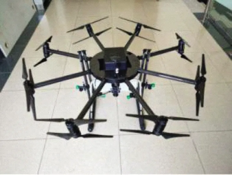
Fig.1 Coaxial sixteen-rotor UAV
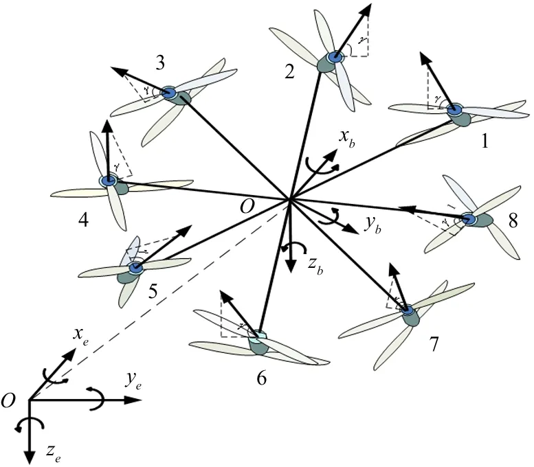
Fig.2 Diagram of coaxial sixteen-rotor aircraft structure
1.2 Attitude estimation in EKF algorithm with 22 dimensional state vector
Traditional attitude estimation based on Kalman filter uses 3-axis attitude angles as the state vector. The integral value of the gyroscope is predicted value of 3-axis attitude angle, while accelerometer and magnetometer serve as observation sensors. Accelerometer information is used to correct the pitch and roll angles, and magnetometer information is used to correct the yaw angle[14,15]. Because the gyroscope and the accelerometer are very sensitive to vibration, a large amount of vibration information is superimposed on the collected original value, which has a great influence on the corrected result of the attitude angle, resulting in a larger error between the estimated attitude angle and the true value[16]. Quaternion-based EKF with 22 dimensional state vector uses unit quaternionq, North, East, down velocityVand positionSas state vectors. The magnetometer, GPS and barometer are introduced as observation sensors to correct the state vector. In addition, the accelerometer biasab, magnetometer biasmb, gyroscope biasωb, and earth magnetic field valuesMare also introduced as the state vector. These state vectors are not directly modified by the state prediction process, but modified by subsequent state observations. Therefore, the state vector is a 22 dimensional vector. The state matrix equation is
(1)
The navigation coordinate systemnis the North-East coordinate system. The body coordinate systembis defined at the origin of UAV,Oxbpoints to the front,Oybpoints to the right andOzbpoints to the bottom. In the attitude estimation, the measure vectors of the body coordinates can be converted to the navigation coordinate by using the coordinate conversion matrixTbnas shown in Eq.(2). In quaternion, the inverse ofTbnis the transposition of itself.
Tbn=
(2)
The attitude angle estimated by the quaternion is
(3)
The roll angle of aircraft is defined as the angle betweenZbaxis and the vertical UAVXbaxis lies in, pitch angle is defined as the angle betweenXbaxis and ground level, yaw angle is between theXbaxis of UAV and the North.
1.2.1 Prediction process of EKF
The process of EKF attitude estimation algorithm includes state prediction, error variance prediction, magnetometer data fusion, GPS/barometer data fusion and optimal estimate of error variance. The main stream of EKF algorithm is shown as Fig.3.
First, the current state is predicted by the optimal estimate of the last state and the amount of control to be applied, and the predictive state equation of the system is established. The prediction process is cited to be ‘State Prediction’, prediction equation is established as
X22×1(k+1,k)=F22×22(k+1,k)X22×1(k)
+G22×6(k+1,k)u6×1(k)
+w22×1(k)
(4)
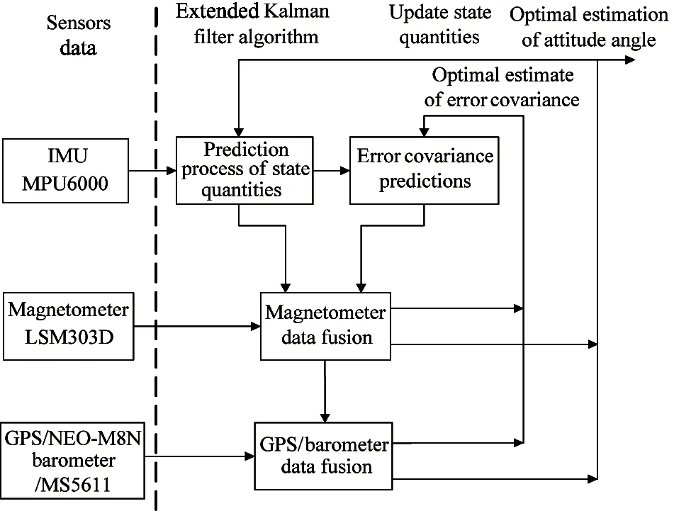
Fig.3 Main stream of EKF algorithm
The matrixF22×22governs the transition of the state vectorsX22×1from momentkto momentk+1.w22×1represents the process noise vector. It is assumed to be zero mean white noise.G22×6is a control matrix andu6×1is control quantity.
In order to calculate theF22×22matrix, it is necessary to find every update equation corresponding toX22×1(k) inX22×1(k+1).
The quaternion renews according to the first order Euler formula for the solution of differential equation, rotate quaternion attitude from previous to new and normalize it.
q4×1(k+1)=q4×1(k)
(5)

The equation for the prediction of velocity from momentkto momentk+1 is
(6)
S3×1(k+1)=S3×1(k)+V3×1(k)Δt
(7)
The predicted values of other state vector are equal to the optimal estimate value at the last moment. The state transition matrix can be obtained by the state prediction equation updated.

(8)
whereIis unit matrix,0is zero matrix.
F4×4=


P22×22(k+1,k)
(9)
aybΔtazbΔt].uis a control vector. Error growth in the inertial solution is assumed to be driven by noise in the delta angles and velocities, after bias effects have been removed.
Q6×6is the covariance matrix of process noisew6×1.Qs22×1is the additional covariance matrix of process noise that stabilizes the filter.F22×22matrix is established in the former. The initial values ofP22×22andQ6×6can be given on the basis of characteristics of different sensors. The calculation methods ofG22×6are as follows.
In order to calculate the matrixG22×6, it is necessary to find every update equation corresponding tou6×1(k) inX22×1(k+1). The amount of control changes the attitude, speed and direction of the aircraft by controlling the speed of the motors. Therefore, the delta angles and velocities are related to the control quantity in theG22×6matrix. MatrixG22×6is calculated from the quaternion and renewal equations according to Eq.(5) and Eq.(6).
where,
σωis the noise variance of 3 axis gyroscopes andσais the noise variance of the 3 axis accelerometer. Each time new IMU data is obtained, the EKF prediction process is repeated.
The prediction process is repeated every time, new IMU data is got until a new measurement from another sensor is available. The EKF algorithm provides a way of combining or fusing data from the IMU, GPS, compass and barometer to calculate a more accurate and reliable estimate of the position, velocity and angular orientation. The updates of magnetometer and GPS data fusion are made in distinct steps.
1.2.2 Magnetometer data fusion for EKF
When magnetometer data is available, EKF enters the process of magnetometer data fusion. Data fusion of magnetometer depends on the 3 basic formula based on Kalman state vector correction. In the 22 dimensional state, the geodetic magnetic stateMis in the navigation coordinate system. The navigation magnetic stateMfrom navigation coordinate can be converted to body coordinate by coordinate conversion matrixTbn. The predicted value of magnetometer on body coordinate is
(10)
The observation value of the magnetometer is
The renewal equation of the observation vector from momentkto momentk+1 can be expressed as
Zm3×1(k)=H3×22(k)X22×1(k)+v3×1(k)
(11)
Taking the axisXas an example. First, calculate the innovationυmxwhich is the difference between the predictedm3×1from Eq.(10) and theZm3×1from Eq.(11):
υmx=mx-Zmx

+2(q1q3+q0q2)MD+mxb
(12)
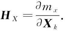
So the observation matrix of theXaxis is


Then calculation of the Kalman gain is
(13)
where,Ris observation noise, its value is determined by the observation sensor.
Updating the state vector, the optimal estimate of the state quantity is
(14)
where,υm3×1=m3×1(k+1)-H3×22X22×1(k+1)
Calculating the covariance of the current state:
(15)
At this point, the magnetometer data fusion is over. Next, the EKF data fusion of GPS/barometer is carried out.
1.2.3 Data fusion of GPS/barometer for EKF
When GPS and barometer data are available, EKF enters the process of GPS/barometer data fusion. The EKF algorithm is used in magnetometer data fusion, and the Kalman filter algorithm is directly used in data fusion of velocity and position. The sensors for velocity and position data fusion are GPS and barometer. GPS directly measures the velocity and position of the horizontal direction and the barometer measures the position in the vertical direction[17], which satisfies the 3 prerequisites of Kalman filter[18].
1) The probability distribution of the current state must be a linear function of the previous state and the control quantity to be performed, and a Gaussian noise is superimposed.
2) The measurement of the state must be a linear function of the state superposed Gaussian noise.
3) The initial state distribution is a Gaussian distribution.
The velocity and position observations provided by the GPS/barometer are as follows.
Jacobi matrix of velocity and position is

(16)
When the measured values of GPS and barometer arrive, the innovation can be obtained according to the current measured values and the previous predicted values[19], so the innovation in the process of Kalman filter isυvs.
(17)
Then calculation of the Kalman’s gainKvsis
(18)
where,Ris measurement noise and its value is determined by the observation sensor.
Updating the state quantity, the optimal estimate of the state quantity is
(19)
Through ‘State Correction’, the optimal estimation state is obtained and the variance matrix is updated. The optimal estimation state is iterated into the next state prediction process.


P22×22(k+1,k)
(20)
So far, the data fusion of magnetometer and GPS/ barometer has been completed. It is able to correct the states by using knowledge of the correlation between different errors and different states[20].
2 Experimental design and algorithm verification
2.1 Construction of test platform
In order to verify the feasibility of the algorithm, a double IMU hardware platform based on STMF429 is designed[21]. It is mainly composed of coaxial sixteen-rotor UAV, inertial measurement unit MPU6000 (integrated gyroscope, acceleration and barometer), magnetometer of LSM303D and NEO-M8N GPS module. Another group of sensors using MTi inertial measurement unit of Holland Xsens company, which has its own Kalman filter algorithm, directly output the high-precision attitude angle. The precision of the roll angle and the pitch angle in the algorithm are±0.3 °, and the precision of the yaw angle is ±0.5 °. The product provides high-quality orientation and positioning, belonging to the high-performance IMU. The internal processor has low power consumption. The output heading angle does not drift, and simultaneously provides 3-dimensional acceleration, angular, velocity and magnetic field strength passing through the nucleus. MTi is a measuring product with excellent performance for the stability and control of cameras, robots, vehicles and other series of equipment. The test platform is shown in Fig.4.
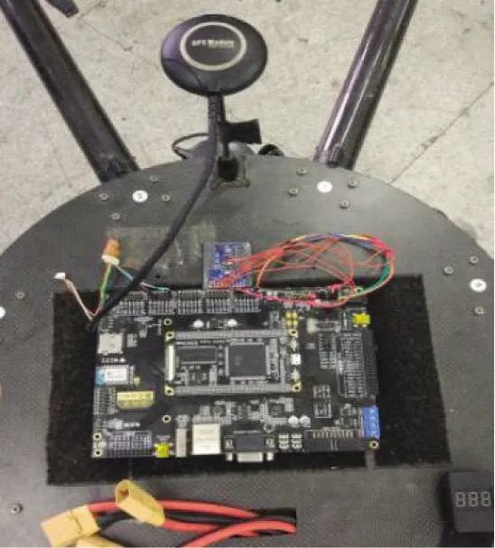
Fig.4 The hardware platform of UAV
In order to ensure the safety of flight test, the attitude angle of MTi is used to guide the flight. The EKF algorithm with 22 dimensional state vector only performs attitude estimation on sensor data without guidance of the flight process. The estimated states are not used for control of the UAVs. All the flight data including the measured sensor data and state vector estimated are stored on board the flight control unit[22-24]. Data acquisition of the MPU6000 inertial sensor is performed at a sampling frequency of 50 Hz. LSM303D Magnetometer updating frequency is 10 Hz, and the NEO-M8N GPS updating frequency is 5 Hz.Therefore, the EKF algorithm of 22 dimensional state vector runs on the STMF429 master control hardware platform. The attitude estimate period is 15 ms and the attitude control period of UAV is 20 ms.
In order to verify the validity of the algorithm, the test is divided into static test and dynamic test. Static tests are used to verify the suppression of low-cost gyroscope drift by the EKF algorithm. While the dynamic tests verify the accuracy of the algorithm.
2.2 Control strategy of coaxial sixteen-rotor UAV
The agriculture UAV has the characteristics of large load and strong vibration when it works, and the continuous spraying of pesticides will cause a non-negligible disturbance to the flight system. Due to this disturbance together with the external disturbance (such as wind), the position accuracy of UAV will be greatly reduced. Therefore, the control strategy of coaxial sixteen-rotor UAV is based on the method proposed by the laboratory before[25]: the control method of combining ADRC and PID. The inner loop is attitude loop, which adopts classical PID control. The outer loop is position loop, which adopts ADRC control method. Through simulation and actual wind disturbance test, it is verified that the controller has strong anti-jamming ability. The block diagram of the overall structure of the control system is shown in Fig.5.
As shown in Fig.5,Xd,Yd,Zdis the desired position;Sn,Se,Sdis the current position;θn,φn,ψnis the current attitude angle, the current position and current attitude angle are provided by EKF;θd,φdis the desired angle output by position controller;ωx,ωy,ωzis the desired angular velocity which is output by attitude controller;Tdis the desired lift force output by altitude controller, and the expected yaw angleψdis directly controlled by attitude controller,Ωdrepresents the control quantity.
The position loop is designed based on ADRC method. It consists of 3 parts: tracking differentiator (TD), extended state observer (ESO) and non-linear state error feedback control law (NLSEF). The control block diagram is shown in Fig.6.
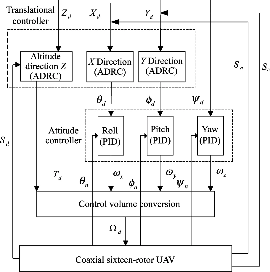
Fig.5 The overall structure of the control system
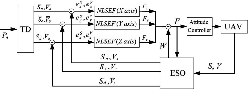
Fig.6 The control block diagram of ADRC control method

For the specific mathematical derivation of the control method combining ADRC and PID, please refer to Ref.[25].
2.3 Static test and result analysis
Put the coaxial sixteen-rotor UAV on the horizontal ground and the yaw angle remains at a non zero angle. Because in zero angle, the yaw angle will jump between 0-180 °. The static test has been executed for approximately 320 s on the horizontal ground. Fig.7 shows attitude estimation under static conditions to reflect gyroscope drift.
The experiment shows that without introducing the vibration interference caused by motor work and external wind disturbance, the precision of the roll angle and the pitch angle of the algorithm are ±0.1 °, the precision of the yaw angle is ±0.2 °. Due to the horizontal ground can not maintain a strict level, there are different degrees of small angle values for the roll angle and the pitch angle. The test results show that the EKF algorithm of 22 dimensional state vector has great advantages for reducing the drift of the gyroscope, and can maintain stable high precision.
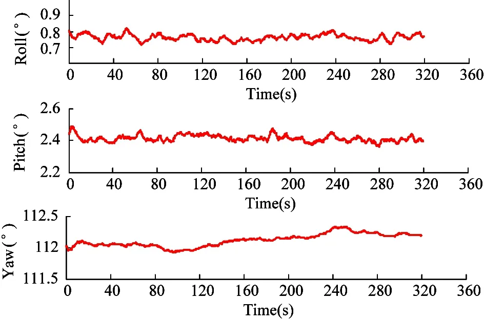
Fig.7 Three axis attitude angle under static condition
2.4 Dynamic test and result analysis
In order to verify the effectiveness of the EKF algorithm of 22 dimensional state vector in UAV dynamic conditions, the dynamic test flies along a high-maneuvered trajectory with a flight time of approximate 400 s. Take the attitude angle of the MTI sensor output as a reference. The parameters of the test UAV are shown in Table 1.
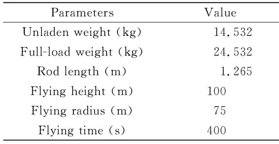
Table 1 Experimental UAV parameters
The scene of the flight test is shown in Fig.8. The 2D trajectory and the height trajectory of the flight test are shown in Fig.9 and Fig.10. Take the take-off position of the UAV as the origin and record the location of every moment during the flight.
The performance of the EKF algorithm in attitude angles is shown in Fig.11. As can be seen from Fig.11, the roll angle, the pitch angle and the yaw angle can accurately track the attitude angle output of the MTi sensor. High precision solution can be maintained under frequent large angle motion and attitude tracking has good real-time performance. It is proved that the algorithm has very high accuracy of attitude estimation.
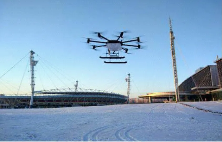
Fig.8 Flight experiment scene
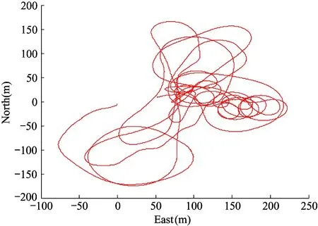
Fig.9 2D trajectories during the flight test
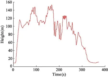
Fig.10 Height trajectories during the flight test
The performance of this EKF algorithm in the position and velocity estimation are shown in Fig.12 and Fig.13. The velocity and position information of GPS output is used as reference. As shown in the figure, in terms of position and velocity estimation, the algorithm performs well. It not only guarantees the long-term accuracy of the algorithm, but also guarantees long-term reliability. According to precision of NEO-M8N GPS, the error of horizontal position estimation is 1 m in the East and North, while according to precision of barometer, the error of vertical position estimation is 0.5 m.
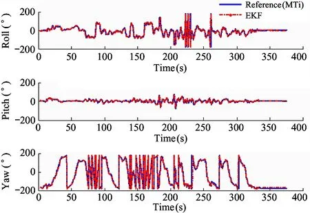
Fig.11 Attitude estimation in comparison to MTi output during the flight test
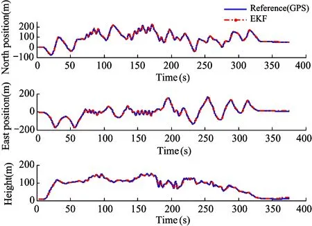
Fig.12 Estimated North-East-Height position comparison to GPS output during the flight test
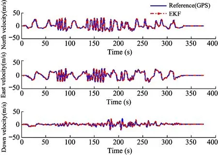
Fig.13 Estimated North-East-Height velocity comparison to GPS output during the flight test
The performance of the proposed EKF algorithm in the accelerometer bias and gyroscope bias estimation is shown in Fig.14 and Fig.15. The initial values of accelerometer bias and gyroscope bias are 0. As shown in Fig.14, the accelerometer bias is always less than 0.1 m/s2and there is no jump phenomenon, which indicates that the filter is stable.
Gyroscope bias is fluctuating when the power is on, which shows that the influence of power on gyroscope is great, but the gyroscope bias converges rapidly and remains stable after short time compensation by the filter.
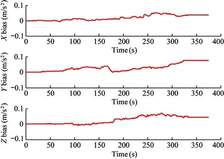
Fig.14 Accelerometer bias error estimates
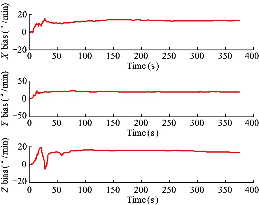
Fig.15 Gyroscope bias error estimates
MN,ME,MDstand for the strength of North, East, Down earth magnetic field. In a certain region, the variation range of geomagnetic field is small, and the optimal estimation can be obtained by the EKF algorithm in the form of ‘self-learning’. As shown in Fig.16, the filter keeps learning the earth’s magnetic field during flight and these value will change slowly.
As shown in Fig.17,Mx,My,Mzstand for the biases ofX,Y,Zbody magnetic field and the initial value is obtained by magnetometer calibration. As earth magnetic field,Mx,My,Mzcan also be obtained by ‘self-learning’.
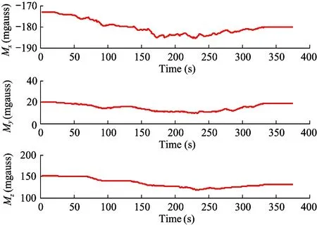
Fig.16 Body magnetic field bias estimates
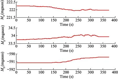
Fig.17 Earth magnetic field estimates
3 Conclusion
The structure of coaxial rotors meets the large load demand of agricultural UAV. The tilt structure of the rotor module solves the problem of insufficient yaw direction control torque caused by traditional UAV relying on anti-torque to control yaw. The creative design improves the mobility and reliability of agricultural UAV.
Attitude estimation method based on EKF algorithm with 22 dimensional state vector for low-cost agricultural UAV is proposed. The bias errors of gyroscope, accelerometer and magnetometer are introduced as the state vector, which makes the optimal estimation of the attitude angle more accurate. It is worth mentioning that all the sensors used in this EKF algorithm are very cheap. Some of the performance indicators of MEMS inertial sensors such as MPU6000 and LSM303D are not as good as that of high precision inertial measurement unit MTi. However, the accuracy of attitude estimated by EKF algorithm is quite similar to that of MTi output attitude angle.
The EKF algorithm with 22 dimensional state vector has fused the data from the MPU6000, magnetometer, GPS, barometer sensors to calculate a more accurate and reliable estimate of position, velocity and attitude angle. It has good performance in both dynamic and static tests.
杂志排行
High Technology Letters的其它文章
- MW-DLA: a dynamic bit width deep learning accelerator ①
- Influence of velocity on the transmission precision of the ball screw mechanism ①
- Physical layer security transmission algorithm based on cooperative beamforming in SWIPT system ①
- GNSS autonomous navigation method for HEO spacecraft ①
- Control performance and energy saving of multi-level pressure switching control system based on independent metering control ①
- Improved image captioning with subword units training and transformer ①
