Control performance and energy saving of multi-level pressure switching control system based on independent metering control ①
2020-07-12CaoXiaoming曹晓明YaoJingShaTongWangPei
Cao Xiaoming(曹晓明), Yao Jing , Sha Tong, Wang Pei
(*College of Mechanical Engineering, Yanshan University, Qinhuangdao 066004, P.R.China) (**School of Mechanical Engineering, Nanjing Institute of Technology, Nanjing 210000, P.R.China)
Abstract
Key words: multi-level pressure, independent metering control, displacement control, energy saving, hydraulic switching system
0 Introduction
Valve-controlled system is widely used in various fields of hydraulic system industry, due to its advantages on the low cost, fast response, and good control performance[1,2]. However, the traditional valve-controlled system usually uses a constant pressure input, resulting in a serious mismatch between the system output and load demand. Meanwhile, the traditional valve-controlled system lacks the ability to meet the different load requirements of multi-actuators, which often causes huge throttling losses, resulting in low transmission efficiency of the system. In addition, with the aggravation of the energy crisis, people pay more and more attention to the energy-saving problem of hydraulic system[3-6].
In recent years, as a new branch of fluid transmission technology, digital fluid power (DFP) has provided some innovative solutions widely[7,8]. Due to its advantages in energy saving, high anti-pollution and multi-function, the theory and technology of DFP has become one of the important development directions in the future hydraulic field[9-11]. In recent years, as a typical application of digital hydraulic technology, hydraulic switching system has received some attention from scholars at home and abroad[12]. Hydraulic switching system mainly could be classified as switching valve-controlled system and switching hydraulic power supply system. The switching valve-controlled system usually utilizes a digital valve with pulse width modulation (PWM) signal, which directly drives the control load to achieve nearly continuous system output and low energy loss[13,14]. However, the switching valve-controlled system has been applied to a certain extent in the low-power hydraulic system. For the high-power hydraulic system, the switching hydraulic power supply system is investigated in actively domestic research that is mainly the switch mode hydraulic power supply proposed by Professor Gu Linyi of Zhejiang University. For pressure boost and buck switching hydraulic power supply, some research work has been done on system principle, system control and energy saving characteristics. However, due to the influence of dynamic and transient losses of components of switching hydraulic power supply, the system will produce greater energy consumption. This restricts the further application of the system[15-17]. The discrete fluid power force system is introduced into the wave energy converter (WEC) hydraulic system by Alborg University. The switching control algorithm of discrete output force is studied, which reduces the energy loss of the system and improves the energy conversion efficiency from wave energy to electric energy[18,19]. Vukovic et al.[20,21]of Aachen University of Technology in Germany proposed a STEAM (steigerung der energieeffizienz in der arbeitshydraulik mobiler mashinen) system, which minimizes throttling loss through valves by switching different pressure levels connected to actuators. The results show that compared with the traditional load sensing system, STEAM system has obvious energy-saving advantages, but there are still some challenges for the hybrid hydraulic system which combines discrete and simulation characteristics.
To solve the problems above, this work proposes a multi-level pressure switching control system (MPSCS). In the previous study, the control and energy saving effects of the system are verified by both theoretical analysis and experiments. However, the switching method of simultaneous switching of 2 actuator chambers is adopted in the MPSCS, which results in pressure impact and displacement jitter[22,23]. In order to reduce pressure impact and displacement jitter, this paper combines independent metering control technology with MPSCS, puts forward a multi-level pressure switching control system based on independent metering control, gives the configuration principle of the system, establishes the mathematical model of the system, and puts forward the control strategy of the system under 4 different working quadrants. Finally, the control and energy saving characteristics of the system are verified by experiments.
1 Configuration
1.1 The principle of MPSCS
MPSCS mainly consists of pumps, valve matrix, actuators, proportional valves, hydraulic transformer and accumulator, etc. (Fig.1). The valve matrix is a rectangular array, arranged inmandn(m≥2,n≥2). The intersections of rows and columns are usually set in on/off valves. The pumps are only used to supply the average power demand, while the hydraulic accumulators are used for peak power requirements and recovering the surplus energy. In addition to the tank pressure rail, the MPSCS can be classified intop1,p2, …,pn. Each pressure level needs an accumulator to maintain the system pressure. The different pressure rails are introduced to minimize the throttling losses across the valves and enable energy recuperation by switching valve matrix. In order to balance the energy among the different pressure levels, the hydraulic transformer is necessary to accomplish the energy transformation.
The essence of MPSCS can select the input pressure supply in real time according to the load variation. When the load is satisfied, the pressure combination with the smaller value of the output force is selected to make the pressure drop across the proportional valve minimized, and to reduce the throttling loss of the valve, so as to achieve the purpose of energy saving[23].
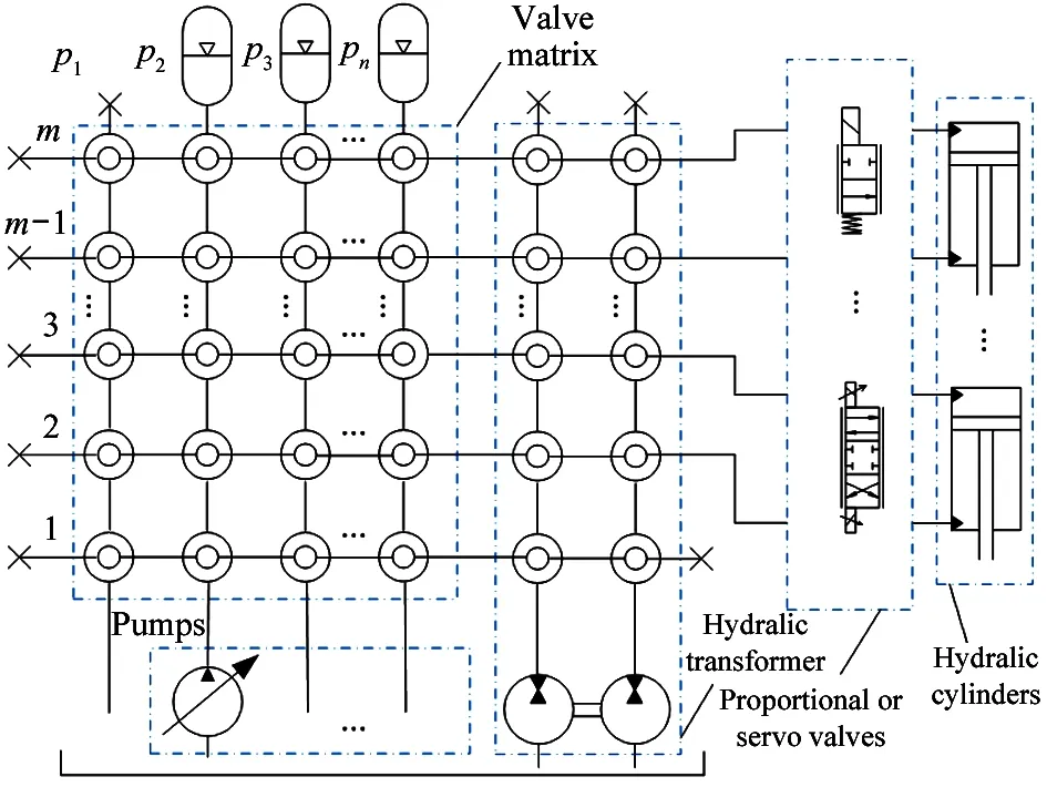
Fig.1 MPSCS schematic
1.2 The principle of MPSCS based on independent metering control
In the previous study, due to adopting the switching method of simultaneous switching of the 2 chambers of the cylinder, the system has certain pressure impact and displacement jitter during the switching. In order to reduce the pressure impact and displacement jitter, the independent metering control technology is combined with the MPSCS. Based on the idea of independent control of the inlet and outlet of the actuator, the flow or pressure of the inlet and outlet of the actuator can be adjusted independently according to the demand in the process of movement, which can improve the dynamic and static response characteristics of the system and improve the efficiency of the system.
Taking the 3 pressure levels ofH,MandTas an example, as shown in Fig.2, an independent valve-controlled cylinder structure composed of 4 proportional valves and a cylinder is designed. This structure can realize 4-quadrant operation of a single actuator. When the cylinder works, one chamber adoptsHandMpressure levels, and the other chamber adoptsTpressure level. By switching the pressure level of one chamber, the jitter caused by frequent switching can be reduced and the energy saving effect can be achieved under the premise of achieving the corresponding control effect and accuracy requirement.
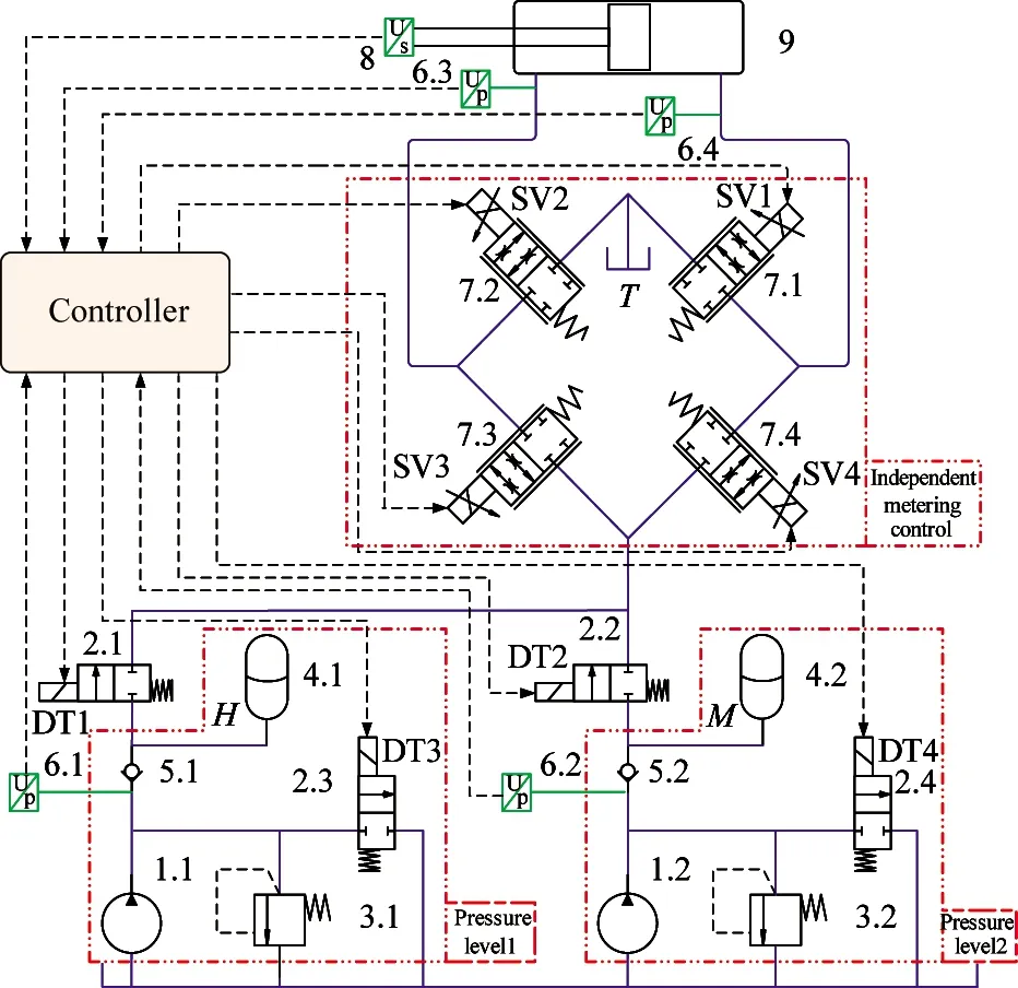
1. Pump 2. On/off valve 3. Overflow valve 4. Accumulator 5. Check valve
6. Pressure sensor 7. Proportional valve 8. Displacement sensor 9. Cylinder
Fig.2 The schematic of MPSCS based on independent metering control
1.3 Energy consumption calculation
In order to quantify the energy consumption of the components and mechanisms of the system, the energy calculation model of the main components and mechanisms is established referring to the process in Ref.[24], which provides a theoretical basis for the experimental analysis of energy consumption calculation.
(1) Energy consumption of pumps
The output power of pumps isPpump, the overall mechanical efficiency isηmand the volume efficiency isηv. Then the total energy consumption of pumps can be expressed as
(1)
where,ηmiis mechanical efficiency of pump corresponding to the pressure leveli,i∈[H, M];ηviis volume efficiency of pump corresponding to the pressure leveli;piis outlet pressure of pump corresponding to the pressure leveli;qiis outlet flow rate of pump corresponding to the pressure leveli.
(2) Energy consumption of proportional valves
The proportional valves also create throttling losses while achieving system control. The throttling loss through the proportional valve is

(2)
where, ΔPthrottle1-ΔPthrottle4are throttling losses through the proportional valves SV1-SV4;q1′-q4′ are flow rates through the proportional valves SV1-SV4;psis system pressure;p1′ is piston chamber pressure of cylinder;p2′ is rod chamber pressure of cylinder;pTis tank pressure.
(3) Energy consumption of cylinder
The output energy consumption of cylinder is as follows:
(3)
where,Pactutatoris output power of the hydraulic cylinder;q1=A1×v,q2=A2×v;A1,A2are piston chamber and rod chamber area respectively;vis velocity of the cylinder.
(4) Energy consumption of load
The energy consumption of load mainly refers to the useful work required to overcome the load:
(4)
where,FLis the load force.
(5) Energy consumption of accumulator energy recovery unit
Under the transcendence condition, the system has an energy recovery function that drives the load to work on the system. The recoverable energy is
(5)
The system energy is recovered by the accumulator and the recovery energy is
(6)
2 Control strategy
Based on the principle and mathematic model of the MPSCS based on independent metering control, the control strategies of impedance extension, impedance retraction, transcendence retraction and transcendence extension are proposed respectively, and the system is analyzed by taking the impedance extension and the transcendental retraction as examples.
The actuator can be divided into 4 quadrants working conditions according to the load forceFLof the system and the speedvof the cylinder as shown in Fig.3.
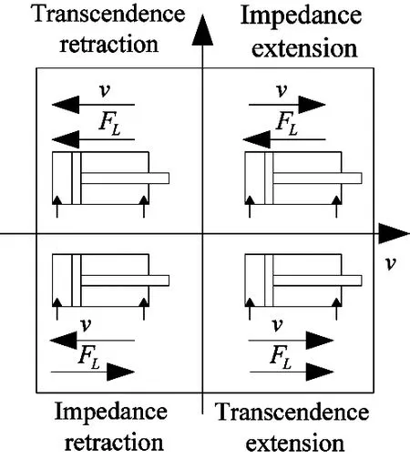
Fig.3 Four quadrant working condition diagram of actuator
For the MPSCS based on independent metering control, 4 independent proportional valves are introduced to realize the control of 4 quadrants working conditions, and displacement is taken as the output target of actuator. One cylinder chamber is required to adopt position control for accuracy control, the other chamber is used to adopt pressure control for back pressure of the return circuit, to increase the smoothness of the actuator. Or the full opening of the proportional valve is connected to the accumulator for energy recovery. The schematic diagram of 4 quadrants working condition control and pressure combination selection is shown in Fig.4.
The current loadFLis detected by force sensor, and the working quadrant is determined according to the velocityvof the cylinder. If the cylinder output is required to meet the load demand, the optimal matching between system and load must ensure the minimum difference between load force and cylinder output force. The different control modes of the four quadrants working condition are respectively described below in Fig.4.
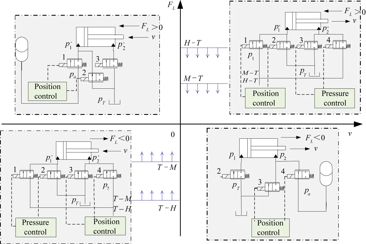
Fig.4 Principle sketch of position-pressure independent metering control
(1) First quadrant-impedance extension
Under this condition, the load force and velocity are both positive, and the control block diagram is shown in Fig.5. Proportional valves 1 and 2 are used for position control in piston chamber to achieve position accuracy control. Proportional valves 3 and 4 are used for pressure control in rod chamber to provide back pressure for system return circuit, so as to reduce the impact and vibration of actuators and increase the stability of motion. By comparing the output force of load forceFLwith that of 2 pressure combinations (M-T and H-T), a pressure combination larger than the load forceFLis chosen as the most energy-saving operation mode at present. The output force of cylinder is matched with the load force to the greatest extent. Then the corresponding pressure level is selected by changing the switch state of valve matrix to reduce the throttling loss of proportional valve and improve the matching efficiency of system.
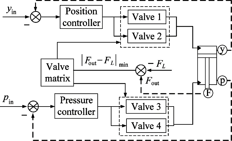
Fig.5 Control block diagram with impedance extension
(2) Second quadrant-transcending retraction
Under this condition, the load force is positive and the velocity is negative, the load is used as the power to drive system, and the proportional valve 2 is used to control the position accuracy, which is connected with the accumulator. The proportional valve 3 is fully opened to absorb oil from the tank, so as to realize energy recovery and storage beyond this working condition, as shown in Fig.6.
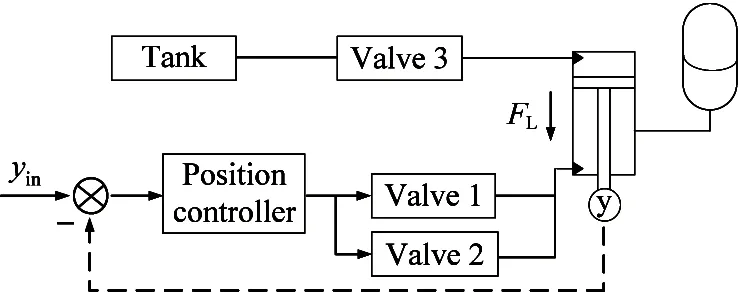
Fig.6 Control block diagram with transcending retraction
The third quadrant-impedance retraction and the fourth quadrant-transcending extension are similar to the first quadrant and the second quadrant respectively, and are not mentioned again.
3 Experiments and discussion
In order to further verify the effectiveness of the system constructed in this paper, an MPSCS based on independent metering control experimental platform is designed and built, and the control and energy-saving characteristics of the 4 working quadrants are studied separately.
3.1 Test principle and equipment
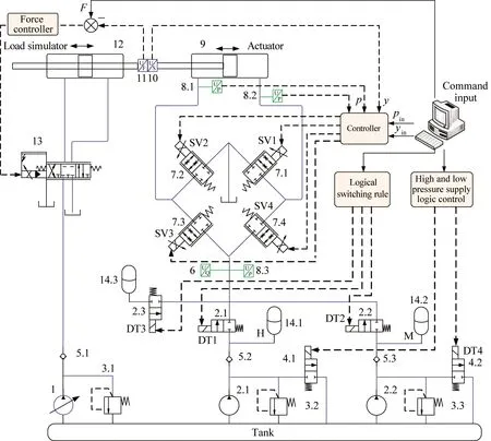
The experimental platform and experimental principle of the MPSCS based on independent metering control system are shown in Fig.7 and Fig.8, respectively. The experimental platform is mainly composed of 2 parts: a hydraulic transmission system and a control acquisition system. The hydraulic transmission system includes a main system and a load simulation system.
The MPSCS based on independent metering control system is mainly composed of variable pump, relief valve, unloading valve, accumulator, proportional valve and pipeline. The main components and sensor parameters are shown in Tables 1 and 2. The function of the load simulation system is to simulate the load in different quadrant working condition. Based on the study of the pressure switching control and energy saving characteristics of the 4 quadrants working conditions, the active load mode of the force closed loop of the valve-controlled cylinder system is adopted in this paper.
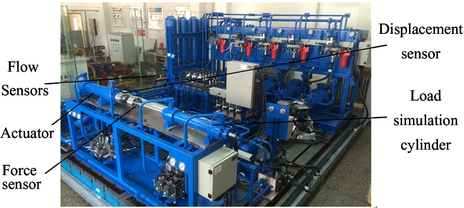
(a) Experimental platform
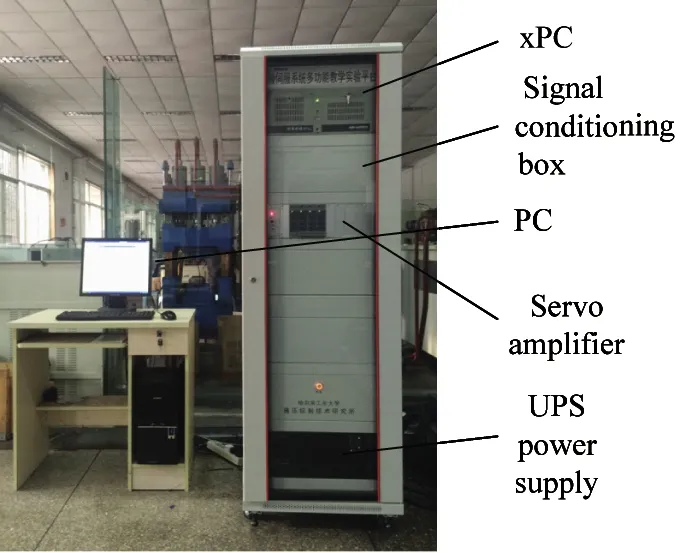
(b) Control acquisition system
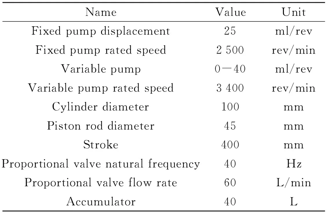
Table 1 Main component basic parameters

Table 2 Main sensor basic parameters
1. Constant pressure variable pump 2.Fixed pump 3. Relief valve 4. Unloading valve 5. Check valve
3.2 Experimental study on characteristics of MPSCS based on independent metering control
The control and energy saving characteristics of the proposed system with 4 quadrants working conditions are verified. Setting the maximum load forceFLmax=50 kN, takingH,MandTpressure levels of 72 bar, 47 bar and 10 bar respectively, four pressure combinations can be obtained, namelyFH-T=50.26 kN,FM-T=30.63 kN,FT-M=-21.57 kN,FT-H=-37.22 kN. It can be seen that the pressure switching points areFM-TandFT-M, and the integral [FM-T]=30 kN and [FT-M]= -20 kN. Considering the pressure drop of proportional valve and the pressure loss of pipeline, there should be a certain pressure threshold when settingHandMgrades, Δp=2 MPa. In order to prevent unloading valves from frequent opening and closing, continuous interval pressure level is adopted, and pressure level intervals are set to [72 bar, 92 bar], [47 bar, 67 bar], respectively. When the working quadrant is transcending, the working pressure of the energy recovery accumulator is about 40 bar.
3.2.1 Analysis of control characteristics of impedance extension
(1) Effect of switching from low pressure supply to high pressure supply on step response
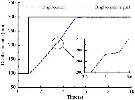
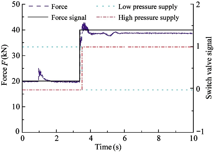
Given the step position of the cylinder from 100 mm to 300 mm, and the step load force from 20 kN to 40 kN, the experimental results are shown in Fig.9.
It can be seen from Fig.9(a) that the step position starts at 1 s, and after 4.7 s the displacement curve reaches a given position of 300 mm, the position accuracy is less than 1 mm, but there is a slow climbing phenomenon at 3.5 s. This is due to the step of load force from 20 kN to 40 kN at 3.5 s, which results in the conversion of force interval fromM-TtoH-T, so the corresponding on/off valve is driven to open and close (Fig.9(b)). At this time, the piston chamber pressure rises from 50 bar to 72 bar, and the input pressure at inlet of proportional valve rises from 57 bar to 80 bar (Fig.9(c)). However, the switching between high and low pressure ranges can only be completed with a certain response time due to the switching valve response and input pressure build-up. The input pressure at inlet of the proportional valve lags behind the change of the pressure in the piston chamber, resulting in the instantaneous zero pressure drop of the proportional valve, the pressure drop of proportional valve tends to zero instantaneously, and the flow rate of system and the velocity of cylinder drop to zero abruptly at 3.5 s (Fig.9(d)). The cylinder has a pressure jitter of ±8 bar at the time of switching, and a steady pressure of 20 bar when it reaches the steady state.
(a) Step position and partial amplification curve
(b) Load curves/switch valve signal
(c) Pressure curves
(d) Velocity and flow curves
Fig.9 Step position characteristic curves
(2) Effect of switching from high pressure supply to low pressure supply on step response
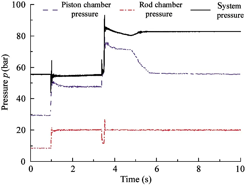
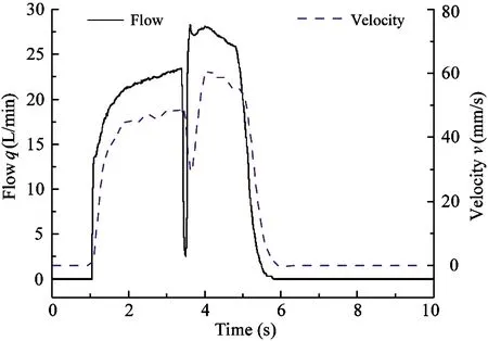
Given the step position of the cylinder from 100 mm to 300 mm, and the step load force from 40 kN to 20 kN, the experimental results are shown in Fig.10.
As shown in Fig.10(a), the step position starts at 1 s, reaches a given position of 300 mm at 5.5 s, and the control precision is less than 1 mm, but at 3.3 s, the position inflection point appears and the ramp increases. This is also due to the load force step from 40 kN to 20 kN at 3.3 s, resulting in the force interval fromH-TtoM-T, and the corresponding on/off valve is opened and closed (Fig.10(b)). At this time, the pressure of piston chamber decreases from 70 bar to 50 bar. Because the switching valve response and input pressure build-up take some time, the input pressure at inlet of the proportional valve lags behind the change of the pressure in the piston chamber, and the input pressure decreases from 75 bar to about 60 bar (Fig.10(c)). However, the pressure drop of proportional valve increases suddenly because of switching from high pressure supply to low pressure supply, which leads to larger flow and velocity impact at 3.3 s of system flow and cylinder velocity (Fig.10(d)). The pressure jitter of ±5 bar occurs when the pressure at the rod chamber of the cylinder is switched, and the given pressure is 20 bar when it reaches the steady state.
(3) Effect of switching high and low pressure supply on ramp position
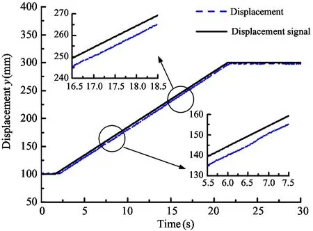
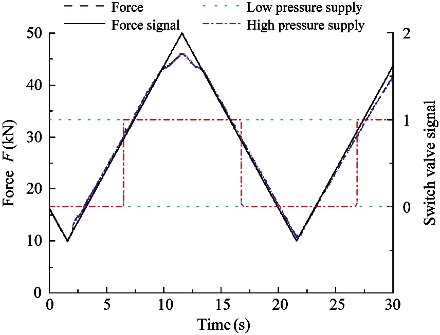
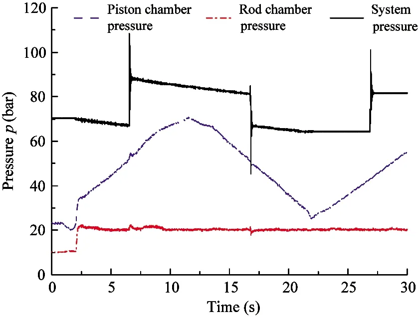
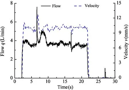
Given a ramp signal with a ramp of 10 mm/s from 100 mm to 300 mm, and a ramp of ±4 kN/s from 10 kN to 50 kN, the experimental results are shown in Fig.11.
As shown in Fig.11(a), the displacement curve can better follow the given position and has a constant position error of 4 mm. There is a sudden change in the following ramp at 6.6 s and 16.8 s. This is due to the change of load force, force interval switching occurs, and pressure and flow impact occurs when the corresponding on/off valve operates. From Fig.11(b), it can
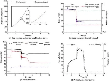
Fig.10 Step position characteristic curves
(a) Ramp position and partial amplification curve
(b) Load curves/switch valve signal
(c) Pressure curves
(d) Velocity and flow curves
Fig.11 Ramp position characteristic curves
be seen that the load force varies according to the given ramp. At 6.6 s, the force interval is cut fromM-TtoH-T, at 16.8 s, fromH-TtoM-T. At 300 mm of maximum displacement, the load force varies according to the given load force signal. At 27 s, the force interval is cut fromM-TtoH-T. The pressure of the piston chamber is consistent with the load force. The switching is accompanied by a pressure impact of about 20 bar. The piston chamber pressure is about 20 bar in the following process, as shown in Fig.11(c). With the change of load force, the pressure drop of proportional valve also changes abruptly when the on/off valve is switched. Therefore, the system flow rate and the cylinder velocity are accompanied by an impact when switching.
3.2.2 Analysis of control characteristic of transcending retraction condition
(1) Step position retraction
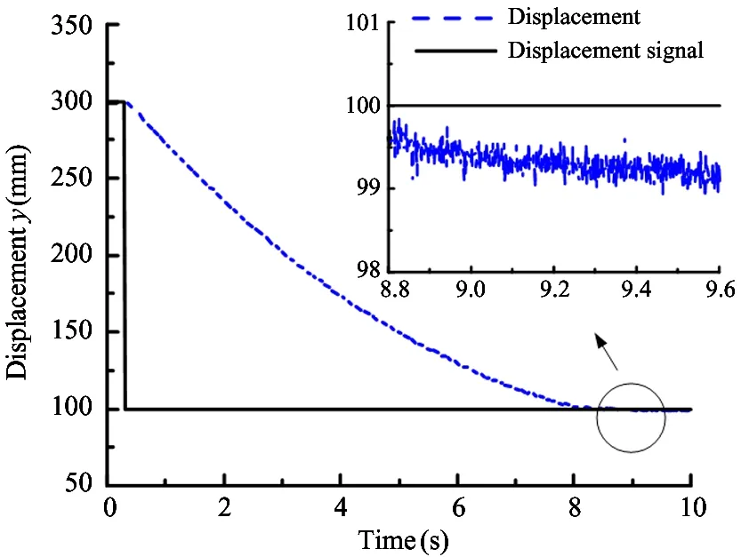
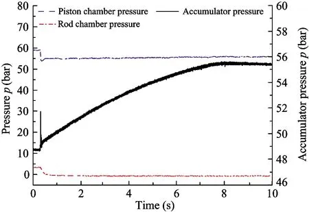
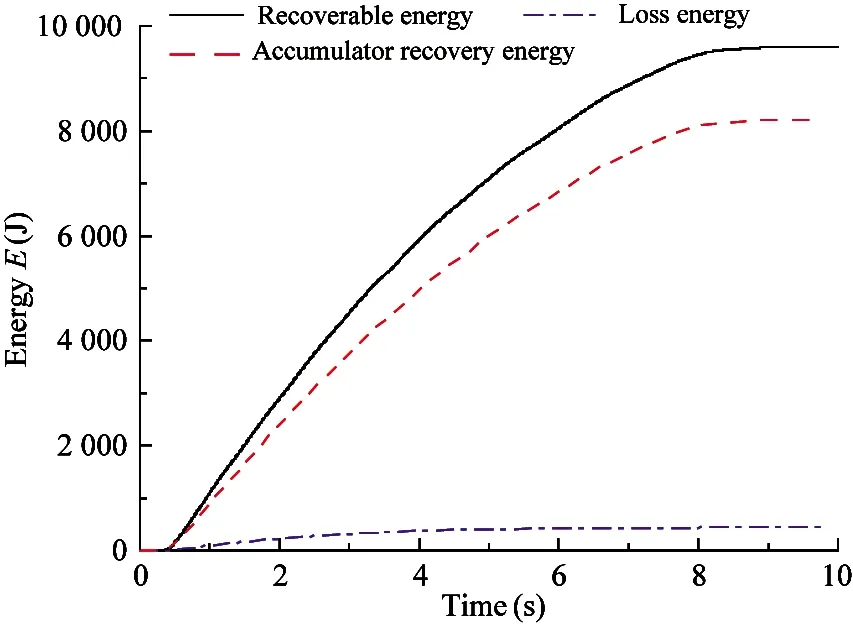
Given the step position signal of 300 mm to 100 mm and the constant driving load of 50 kN, the position control and energy recovery characteristics of accumulator are experimented under the constant driving load of cylinder. The experimental results are shown in Fig.12.
As shown in Fig.12(a), the displacement reaches the specified position of 100 mm at 9 s with a control accuracy of less than 1 mm. It can be seen from Fig.12(b) that since the rod chamber pressure is sucked from the tank, the pressure is about -1 bar, and the piston chamber pressure is about 55.2 bar. The proportional valve is connected for position control, and the pressure of the accumulator rises gradually from 48.5 bar to 55 bar due to energy recovery. The energy recovered from the load is about 9 609 J, but due to throttling loss of proportional valve (about 435 J) and friction loss of pipeline and cylinder, the energy recovered by accumulator is about 8 222 J, accounting for 85.56% of the recoverable energy.
(2) Ramp position retraction at constant load
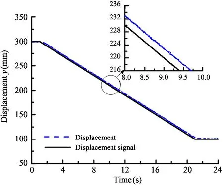
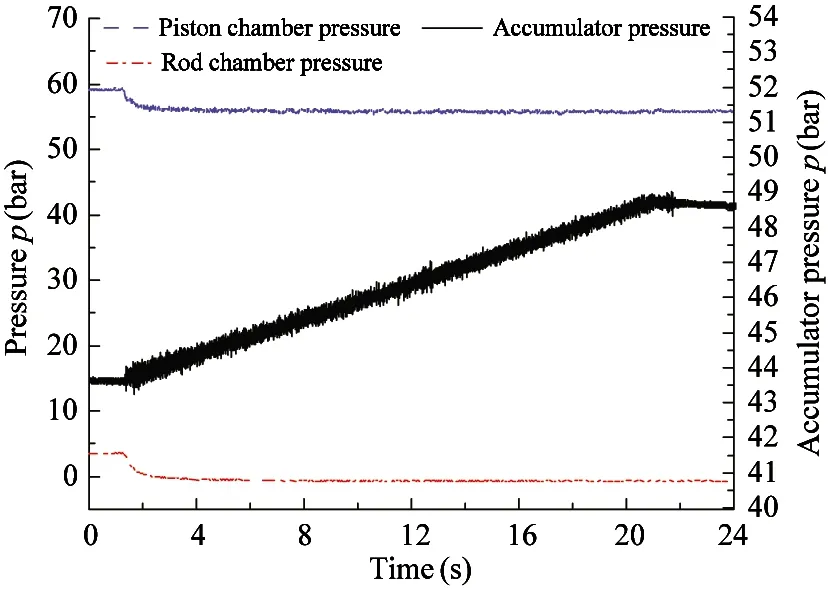
Given the ramp position signal from 300 mm to 100 mm, the ramp is -10 mm/s, and the constant driving load of 50 kN, the experimental results are shown in Fig.13.
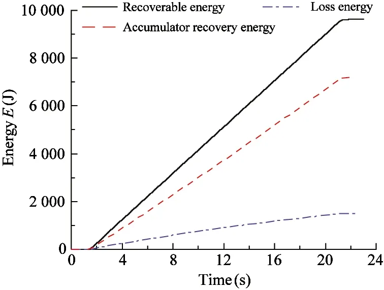
From Fig.13(a), the displacement curve of the cylinder follows the input well, with a displacement error of about 3 mm. As shown in Fig.13(b), the pressure in the rod chamber is negative pressure about -1 bar, and pressure in the piston chamber is about 55 bar. The proportional valve is connected for position control, and the accumulator pressure is gradually increased from 43.5 bar to 48.7 bar. The energy recovered by the load is about 9 627 J, and the energy recovered by the accumulator is about 7 192 J, accounting for 74.7% of the recoverable energy.
(a) Step position and partial amplification curve
(b) Pressure curves
(c) System energy curves
(3) Ramp position retraction at variable load
Given a ramp position signal from 300 mm to 100 mm with a ramp of -10 mm/s and a driving load force signal with a ramp of 5 kN/s from 40 kN to 50 kN, the experimental results are shown in Fig.14.
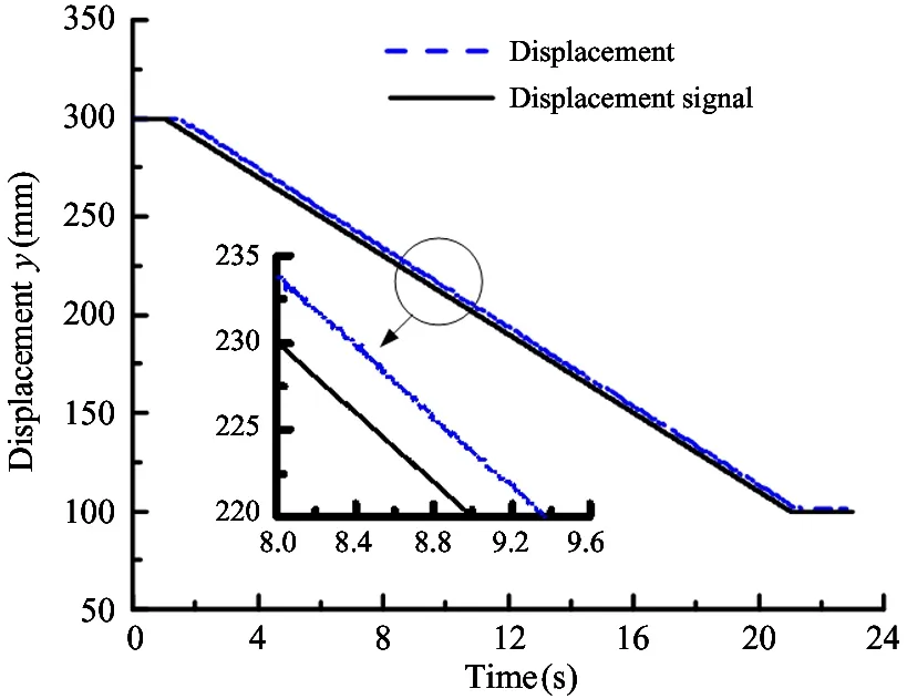
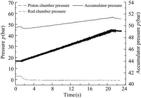
As shown in Fig.14(a), the displacement can follow the input well, with a displacement error of about 4 mm. From Fig.14(b), it can be seen that the rod chamber pressure is negative pressure about -1 bar, and the piston chamber pressure increases from 46 bar to 57 bar with the change of load force. The proportional valve is connected for position control, and the accumulator pressure rises from 44 bar to 49 bar. The recoverable energy is about 8 753 J, and the energy recovered by the accumulator is about 7 270 J, which is 83% of the recoverable energy.
(a) Ramp position and partial amplification curve
(b) Pressure curves
(c) System energy curves
(a) Ramp position and partial amplification curve
(b) Pressure curves
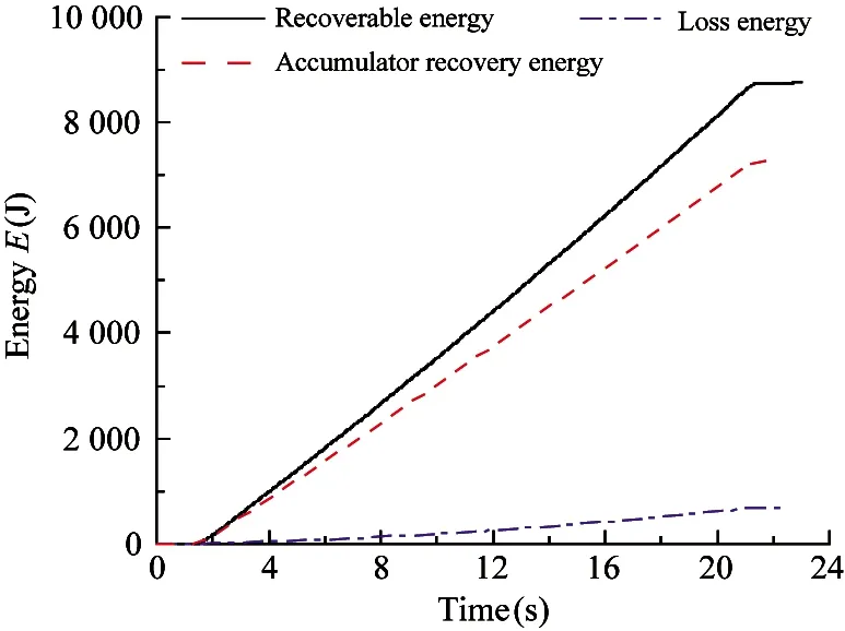
(c) System energy curves
4 Conclusion
This work proposes an MPSCS based on independent metering control, and expounds the principle of this system, aiming to improve the load matching and energy utilization, reduce system throttling loss, input power and achieve energy recovery. At the same time, to achieve the purpose of reducing the energy consumption of the system.
The mathematical model of MPSCS based on independent metering control and its energy consumption transfer model are established. On this basis, 4 quadrant working condition control strategies are proposed, the working mode and switching principle of the controller based on working quadrant are formulated.
An experimental platform is built to test the control and energy consumption characteristics of the proposed new system. The test results show that the MPSCS based on independent metering control has certain influence on the response of step position and ramp position under impedance condition. The displacement curve shows slow climbing or abrupt change of displacement ramp. The displacement follows well under ramp signal, and the position accuracy is about 1 mm. In the case of transcending condition, energy recovery and storage can be carried out. The displacement under the signal follows well, the control accuracy is about 1 mm, and the energy recovery is about 70%-80%.
杂志排行
High Technology Letters的其它文章
- MW-DLA: a dynamic bit width deep learning accelerator ①
- Influence of velocity on the transmission precision of the ball screw mechanism ①
- Physical layer security transmission algorithm based on cooperative beamforming in SWIPT system ①
- GNSS autonomous navigation method for HEO spacecraft ①
- Improved image captioning with subword units training and transformer ①
- RGB and LBP-texture deep nonlinearly fusion features for fabric retrieval ①
