Dynamics Analysis of Fractional-Order Memristive Time-Delay Chaotic System and Circuit Implementation
2020-05-21DaweiDingHuiLiuYecuiWengXiaoleiYaoandNianWang
Dawei Ding, Hui Liu, Yecui Weng, Xiaolei Yao and Nian Wang
(School of Electronics and Information Engineering, Anhui University, Hefei 230601, China)
Abstract: The integer-order memristive time-delay chaotic system has attracted much attention and has been well discussed. However, the fractional-order system is closer to the real system. In this paper, a nonlinear time-delay chaotic circuit based on fractional-order memristive system was proposed. Some dynamical properties, including equilibrium points, stability, bifurcation, and Lyapunov exponent of the oscillator, were investigated in detail by theoretical analyses and simulations. Moreover, the nonlinear phenomena of coexisting bifurcation and attractor was found. The phenomenon shows that the state of this oscilator was highly sensitive to its initial value, which is called coexistent oscillation in this paper. Finally, the results of the system circuit simulation accomplished by Multisim were perfectly consistent with theoretical analyses and numerical simulation.
Keywords: fractional-order; time-delay; coexisting attractors; coexisting bifurcation; circuit simulation
1 Introduction
Before 1971, it was generally believed that basic circuit elements comprised three well-known components: resistance, inductance, and capacitance. However, after the publication of the missing circuit element by Chua[1], the discovery of memristor changed people’s traditional perception of electronic circuits. Memristive systems with integer-order have been well discussed, but fractional-order memristive systems have rarely been studied.
Fractional calculus plays a very important role in various fields of science and engineering. In 1974, Oldham & Spanier[2]gave it a complete mathematical presentation. A large number of studies show that the fractional-order model can depict the characteristics of the actual system more accurately. One year later[3], described a fractional-order memristor-based classical Chua’s oscillator, in which the memristor is a flux-controlled memristor. Since then, a lot of research has been focused on fractional-order memristor models and fractional-order memristor-based systems[4-8].
The nonlinear dynamic of the fractional-order delayed chaotic system has been analyzed[9-14]. In Ref.[13], the researcher analyzed the bifurcation oscillators with delay. In addition, the crucial focus chaos behaviors in the fractional time-delay chaotic system were also investigated[15-16]. However, most of the current researches are limited to mathematical models. No circuit experiments have been conducted[17-18]. In this paper, we propose a nonlinear time-delay chaotic circuit based on fractional-order memristive system. Results of the system circuit simulation accomplished by Multisim are consistent with theoretical analysis and numerical simulation. The structure of this article is as follows: In Section 2, we propose a fractional-order memristor and analyze the electrical characteristics of the fractional-order memristor. In Section 3, we propose a fractional-order memristive delayed chaotic circuit and present the phase portraits of the proposed fractional-order memristive delayed chaotic circuit. Section 4 provides a detailed analysis on the dynamic behaviors of the memristive circuit mentioned. Remarkably, the results of the system circuit simulation accomplished by Multisim are perfectly consistent with theoretical analyses and numerical simulation in Section 5. Finally, the conclusions are given in Section 6.
2 Modeling and Analysis of Fractional-Order Memristor
2.1 Fractional Calculus

(1)

In the development of fractional calculus theory, the initial conditions corresponding to the Riemann-Liouville derivatives have no physical meaning, while the initial conditions of the systems described by the Caputo derivatives have clear physical meanings and the forms are similar to the integer-order differential equations. The fractional derivative off(t) is as follows:
(2)
where 0≤n-1≤q≤n,n=[q]+1, [q] is the largest integer not exceedingq, Γ(n) is the Euler Gamma function,x(n)(t) is then-order derivative ofx(t), Γ(·) is the Gamma function, which is a function of a variablexdefined via a convergent improper integral

(3)
n∈Nis the first integer which is not less thanα. It is a fractional derivative of a continuous function of time, namelyf(t), which is given in terms of a time integral. Under natural conditions on the functionf(t), the Laplace transform satisfies
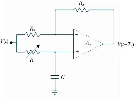
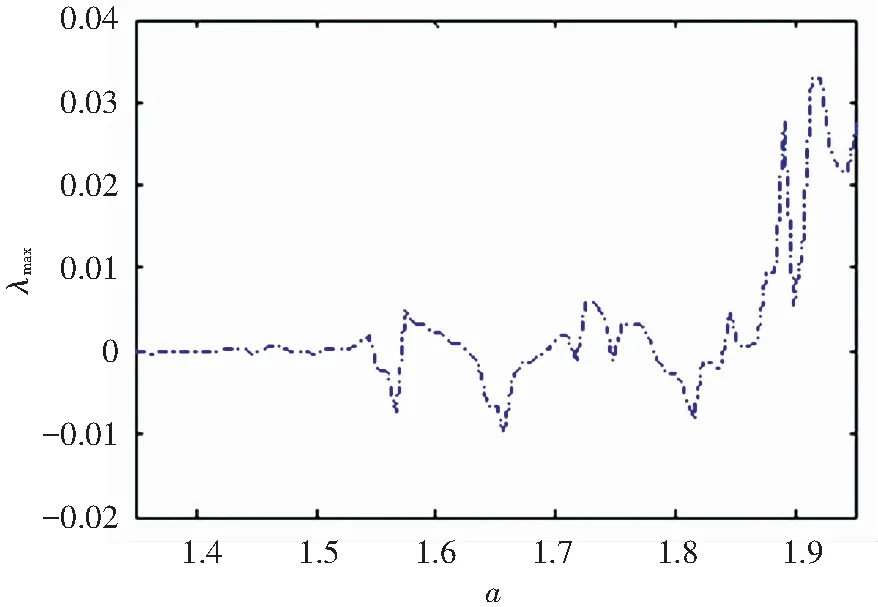
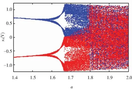
(n-1 (4) Muthuswamy et al.[19]studied the flux-controlled memristor model equivalent realization circuit shown in Fig.1. It consists of three remote arithmetic amplifiers, five resistors, two multipliers, and one capacitor. The first stage op ampU1circuit can avoid the load effect. The second stage op ampU2circuit connected to resistorR0and capacitorC0is an integrator. The mathematical model describing the memristive behavior is established as follows: (a) Schematic of the memristor (b) Flux-controlled memristor symbol Fig.1 Flux-controlled memristor and the corresponding circuit realization (5) wherex1is the input of the memristor,x2is internal state of the memristor,f(x1,x2) is the output of the memristor.g1is the variable scale factor in multiplierM1,g2is the variable scaling factor in multiplierM2. Assumeα=R1-1-R2-1,β=g1g2/R2in the active magnetron memristive equivalent circuit described by the quadratic nonlinear characteristic curve in Fig.1. Thus, we setR0=8.2 kΩ,C0=47 nF,R1=750 Ω,R2=1.5 kΩ,R3=R4=8.2 kΩ,g1=0.1,g2=1.3. The equivalent parameters for the proposed active magnetron memristor can be calculated asα=0.666 7 ms andβ=0.008 7 S/Wb. In practical calculations, there are a variety of methods to solve fractional calculus. By obtaining the complex frequency domain transfer function 1/sq, the expanded form of the complex frequency domain is obtained and the complex frequency domain form is converted into the time domain form for numerical solution. Ref.[20] introduced a Bode graph approximation method. We determined the expansion ofF=1/sq. Ref.[21] derived the 1/sqexpansion ofqfrom 0.1 to 0.9. In order to implement the equivalent circuit of fractional-order memristor shown in Eq. (8), we first considered applying the approximation technique proposed by Oustaloup to get the approximate transfer function of the fractional-order integrator operator[22]. We designed a unit circuit that implements a 1/sqexpansion ofqfrom 0.1 to 0.9 based on the 1/sqexpansion of the approximate error of 2 dB, as shown in Fig.3. The complex frequency domain expression of the equivalent circuit is as follows: (6) whereCis the unit parameter. LetC=1 μF,H(s)=1/sq. Table 1 gives the approximate transfer functions of fractional integratorF(s) when fractional orderqis selected as 0.6, 0.7, 0.8, 0.9. The corresponding resistance and capacitance values are shown in Table 2. Table 1 Boolean approximation of 1/sq Table 2 Calculated values of resistances and capacitances Then, we used electronic circuits to achieve the fractional-order flux-controlled memristor in the complex frequency domain as shown in Fig.2, with a unit circuit (Fig.3) for implementing the approximate transfer functions of fractional-order integrator operator depicted in Table 2. According to the concept of fractional calculus, the real capacitor can be extended to fractional-order to describe the real electricity characteristics[23]. In this paper, the integer-order capacitorCin the memristor is actually fractional-order capacitor in reality. The fractional-order unified model of memristor is derived as follows: (7) whereqis the order of the fractional-order. (a) The schematic of the fractional-order memristor (b) Flux-controlled memristor symbol Fig.2 Fractional-order flux-controlled memristor Fig.3 Unit circuit for implementing the fractional-order integrator ‘1/Csq’ To prove the validity of the theory mentioned above, circuit simulations were carried out to realize the memristor. The driven voltage was chosen asx1(t)=X1sin(2πft)V. WhenX1=4 V, the current-voltage curve is described in Fig.4. (a) Influence of the order q on the hysteresis loop when f=100 Hz (b) Influence of the frequencyfon the hysteresis loop whenq=0.9 Fig.4 Pinched hysteresis loop of the fractional-order memristor Fig.4(a) exhibits the pinched hysteresis loop whenf=100 Hz and the fractionalqis 0.6, 0.8, and 0.9, respectively. Fig.4(b) exhibits the pinched hysteresis loop whenq=0.9 andfequals to 100, 200, and 500 Hz, respectively. Through simulation experiments, we concluded that in the same frequency, as the orderqincreases, the area of the pinched hysteresis loop increases monotonically; in the same order, as the frequencyfincreases, the area of the pinched hysteresis loop decreases monotonically. Ref.[24] compared the APF with the LCL, Bessel delay circuit. Other delay circuits have their own shortcomings. APF is the most efficient compared with other delay blocks. Therefore, APF experimental system was chosen in this paper. This delay unit is included by a series of All Pass Filter (APF) as shown in Fig.5[25]. The same delay unit is used in Refs.[26-27]. Variable delay was studied as delay blocks. The transfer function of the APF is as follows: (8) The flat gainq1=1 is determined byR8andRg. TD≈RC is the time delay provided by each APF block. Thus this delay unit needsisections to realize a delay TD≈iRC, (i=1,2,3). Fig.5 Active first-order all pass filter (APF) Because TD changes with the resistance change of the sliding rheostat, in order to avoid emergency, we used two time-delay modules in series as shown in Fig.5. In this module, we present a circuital realization of the fractional-order memristive delayed Chaotic system (9) to prove the feasibility and correctness of the theoretical model. The designed circuit is shown in Fig.6. Fractional-order memristive device and delayed unit was analyzed in Ref.[28]. The equation of the circuit in Fig.6 is derived as follows: (9) The fractional-orderqis set to be 0.9, and initial values are set to bex1=0.1 V,x2=0.1 V. In this paper, we studied delayed memristive chaotic system in Fig.6[29]. Fig.6 Delayed chaos circuit based on fractional-order memristor Subsequently, we performed numerical simulation on the decomposed fractional mathematical model. The simulation was carried out by MATLAB, via utilizing the predictor-corrector method to simulate the fractional differential Eq. (9).Other parameters include fractional orderq=0.9,l=2.5,b=-2,τ=1 and initial values (0.1, 0.1). In order to easily see the influence of the parameteraon the time-delayed chaotic circuit of the fractional memristor, we drew the two-dimensional phase diagrams and time-series plots of different parametera, as is shown in Fig.7. The phase portrait is a stable limit cycle with parametera=1.62 as shown in Fig.7(a). The corresponding time-series plots is shown in Fig.7(b). When parametera>1.64, the system goes into a chaotic state. When parametera>1.64, the real time and phase plane plots are shown in Fig.7(c) and Fig.7(d), respectively. When parametera≥1.7, the system enters double-scroll chaotic attractor in Fig.7(e)-(f). Fig.7 Phase plane and time-series plots for variable a (10) whereXandXτare the column vectors (x1,x2) attandt-τ, (11) and (12) Theorem1We can get all the roots of the characteristic equation[30] det(sqI-J-exp(-sτ)Jτ)=0 (13) whereIis the identity matrix. The necessary factor for the system (9) to generate chaos is that Eq.(13) has the root of the real part. Thus we have the following equation: (14) Based on Eq.(14), the characteristic equation is as below: s2q+A1sq+A2sqe-sτ+A3=0 (15) where (16) Assuming that a root of Eq.(15) iss=iw=|w|(cos(π/2)+isin(±(π/2))), andwis a real number, whenw>0, we obtain isin(π/2); whenw<0, we obtain -isin(π/2). Real and imaginary parts are separated, then we get (17) We assume (18) and (19) We set (20) Then, we get |ω|4q+ψ1|ω|3q+ψ2|ω|2q+ψ3|ω|q+ψ4=0 (21) where (22) We can calculate the root of Eq.(21). We set y(ω)=|ω|4q+ψ1|ω|3q+ψ2|ω|2q+ψ3|ω|q+ψ4 (23) Lemma1For Eq.(15), the following results hold: (a) IfΨk>0(k=1,2,3,4) andA3+A40, Eq.(15) has no root with zero real parts for allτ≥0. (b) IfΨk>0(k=1,2,3,4) andΨk<0, Eq.(15) has a pair of purely imaginary roots ±wwhenτ=τj,j=0,1,2,…, where (24) wherej=0,1,2,…;k=1,2,3,…, andw0is the unique positive zero of the functiony(w). Proof (a) FromΨK>0(k=1,2,3,4), we obtainy=(0)=Ψ4>0, y′(ω)=4q|ω|4q-1+3ψ1q|ω|3q-1+ 2ψ2q|ω|2q-1+ψ3q|ω|q-1 (25) Combineq>0 andΨk>0(k=1,2,3,4) we get that Eq.(15) has no real root. Hence, Eq.(15) has no purely imaginary root, provided thatA3+A4≠0,Ψ4<0 is not a root of Eq.(15). As the system parameterachanges, balance point of the fractional-order delayed chaotic system, stability of the system, and state of the system will alter. The largest Lyapunov exponent and bifurcation diagram of the fractional-order delayed chaotic system are considered in order to demonstrate the chaos. Under the initial condition (0.1, 0.1), whenachanges in the range [1.35, 2], the maximum Lyapunov exponent and bifurcation diagram of the fractional-order delayed chaotic system is shown in Fig.8. For better observation, the maximum Lyapunov exponent of the fractional-order delayed chaotic system is basically consistent with the bifurcation diagram. (a) Bifurcation diagram a(q=0.9) (b) Largest Lyapunov exponent of q=0.9 Fig.8 Dynamical behaviors with differenta(q=0.9,l=2.5,b=-2,τ=1) It is obvious that the orbits of the memristive circuit start from the periodic state, then whenapasses through the threshold, Hopf bifurcation appears, and finally turn into chaotic state with the increase ofa. When parameteraincreases to 1.62, the phase portrait of the system (9) turns to be a limit cycle. Besides, with decrease of parametera, the orbit degenerates into a single-scroll attractor as shown in Fig.7(c). When we setq=0.9,l=2.5,b=02,τ=1, parameterachanges in the range [1.35, 2], and the state initial values are (0.1, 0.1) and (-0.1,-0.1) by blue and red, respectively, it is clear from Fig.9 that there is a coexistence bifurcation mode phenomenon. In the case of different initial values, the system’s bifurcation diagram is inconsistent. Fig.9 Bifurcation diagram of initial values (0.1, 0.1) and (-0.1,-0.1) withaas a varying parameter (q=0.9,l=2.5,b=-2,τ=1) According to dynamics given in Fig.10, when parametera>1.64, the system (9) manifests coexisting attractors. When parametera=1.68, the state initial values are (0.1, 0.1) and (-0.1,0.1) by blue and red, respectively. The coexistence of single-scroll chaotic attractors are shown in Fig.10(a), and the state initial values are (0.1, 0.1) and (-0.1,-0.1) by blue and red, respectively, as is shown in Fig.10(b). When parametera=1.73, the state initial values are (0.1, 0.1) and (-0.1,-0.1). The coexistence of double-scroll chaotic attractors are expressed in Fig.10(c). From this phenomenon, we know that the fractional-order memristive time-delay chaotic system has wealth dynamic characteristics. Fig.10 Coexisting attractors with different parameter a and initial values To confirm the theoretical investigations, circuit simulations are carried out by Multisim. The structure of the circuit was designed as Fig.11 whenqis 0.9. The proposed circuit was designed on Multisim software using op-amp AD711KN and multiplier AD633JN with15 volts andR=11.24 kΩ. The phase plane and time-series plots for variableais as shown in Fig.12. The phase portrait is a stable limit cycle whena=1.62, a single-scroll chaotic attractor whena=1.68, and a double-scroll attractor whena=1.73. Simulation results demonstrate the influence of parameteraon chaotic behaviors. Fig.11 Schematic of the circuit structure Fig.12 Phase plane and time-series plots for variable a In this paper, we presented a fractional-order memristive delayed chaotic system. Some dynamical properties, including equilibrium points, stability, bifurcation, and Lyapunov exponent of the oscillator, were investigated in detail by theoretical analyses and simulations. Moreover, we also found the nonlinear phenomena of coexisting bifurcation and coexisting attractor. The phenomenon shows that the state of this oscilator was highly sensitive to its initial value, which is called coexistent oscillation in this paper. Besides, the results of the circuit simulation accomplished by Multisim were perfectly consistent with theoretical analyses.2.2 Fractional-Order Flux-Controlled Memristor


2.3 Delay Circuit

3 Fractional-Order Memristive Time-Delay Chaotic Circuit


4 Analysis of Dynamical Behaviors
4.1 Stability of Equilibrium Points


4.2 The Largest Lyapunov Exponent and Bifurcation Diagram


4.3 Coexistence Attractors and Coexisting Bifurcation Mode


5 Experimental Research on Circuit


6 Conclusions
杂志排行
Journal of Harbin Institute of Technology(New Series)的其它文章
- Review: Energy Methods for Multiaxial Fatigue Life Prediction
- Biodegradation of Ammonia Nitrogen Using a Novel Candida sp.Strain N6 Immobilization
- Loop Closure Detection of Visual SLAM Based on Point and Line Features
- An LCC-HVDC Adaptive Emergency Power Support Strategy Based on Unbalanced Power On-Line Estimation
- Aging Behavior and Creep Characteristics of CACB
- Effect of Crowding in Metro Carriages on Travelers’ Disutility:An Evidence from Guangzhou Metro
