On the dynamically formed oxide films in molten Mg
2020-04-29MohammadMahdiJalilvandMehdiAkbarifarMehdiDivandariHassanSaghafian
Mohammad Mahdi Jalilvand, Mehdi Akbarifar, Mehdi Divandari, Hassan Saghafian
School of Metallurgy and Materials Engineering, Iran University of Science and Technology (IUST), Narmak, Tehran, 16846-13114, Iran
Abstract The so-called “Oxide/Metal/Oxide sandwich” method is one of the technique used to investigate the dynamic oxidation of metals which happens during the casting process. In this study, characteristics of the oxide films formed on the molten magnesium in dynamic conditions have been investigated using the aforementioned method. The air bubbles were released into the cast sample at the pressure of 0.2 atm through a quartz tube of 1mm internal diameter. The interface of two adjacent entrapped bubbles is considered as the Oxide/Metal/Oxide(OMO) sandwich. The sandwiches were characterized by the aid of the optical and scanning electron microscopy and also X-Ray diffraction analyses. Two different approaches, including measuring the width of the folds formed on the oxide films and the edge of the sandwiches,were used to estimate the thickness of the films. The thicknesses were estimated to be in the range of 200 to 800nm. The features such as fold, wrinkle, and crack were observed on the OMO sandwiches. On the microscopic scale, the oxide films were rough and porous.This is attributed to the non-protective behavior of oxide films. The XRD patterns indicated that the oxide films formed on the pure molten magnesium in dynamic conditions are crystallized MgO.
Keywords: Dynamic oxidation; Bifilm; Magnesium; Oxide films; Casting defects.
1. Introduction
Magnesium and its alloys show high affinity to oxidation,especially in the molten state. Literature indicates that at temperatures below 250°C, a protective oxide film forms on the solid magnesium surface and kinetics of the oxidation follows a parabolic law [1]. At the higher temperatures, the film becomes porous. As a result of that, the surface can’t be protected against the atmosphere and the oxidation will continue with a linear dependence with the time [1,2].
In an unprotected atmosphere, magnesium melt tends to continuously react with oxygen until all the Mg content turns to oxides [3–5]. Thermodynamics calculations suggest that at 700°C, an oxygen partial pressure of 5×10−54atm is enough for magnesium oxidation [6]. In order to tackle the problem, taking the benefit of the protective fluxes and gases[7], vacuum melting [8], and designing of the alloys with higher ignition temperature have been proposed [9–12].
The majority of the researches on Mg oxidation are concerned with the oxidation in the solid state. Due to the high reactivity of the Mg melt,studying the oxidation of the molten Mg have been carried out in a protective atmosphere [13–16].However, during the casting process, oxidation of the molten metal occurs in two stages including: a) melting, and b) pouring stages. The oxidation of metal during the melting step is categorized as static oxidation. While, the pouring step oxidation in which the surface turbulence changes the state of the oxidation, is known as dynamic oxidation. The last case would lead to formation of the double layer oxides (Bifilms)in casting parts [17]. The double oxide layers not only deteriorate the mechanical performances of the castings but also can act as the preferential sites for the nucleation and growth of gas and shrinkage porosities [18,19].

Fig. 1. A view of the designed model for the casting practice.
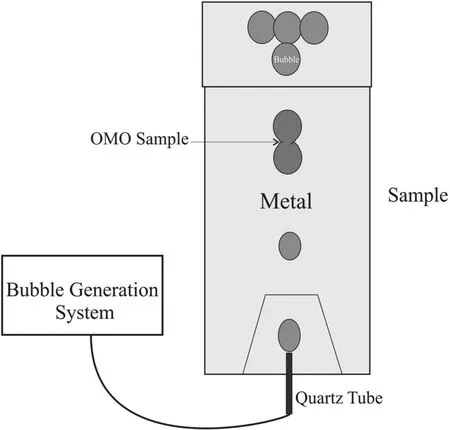
Fig. 2. Schematic of bubbles entrapment and formation of the OMO sandwiches.
During the dynamic conditions i.e. melt pouring step of the casting process, the oxide films are being subjected to deformation forces which causes the characteristics of the dynamically formed oxides to be different from the stagnant oxides [20]. To simulate and provide the dynamic conditions during pouring step, Divandari and Campbell [21] have devised a technique in which artificial bubbles are introduced to the melt. In this method, releasing the bubbles into the melt leads to the formation of an oxide/metal/oxide sample.The mutual layer between two adjacent bubbles hands out unique information about the oxide films formed on the melt in dynamic conditions [22]. Due to the fact that these oxide films form in a very short period of time, they are considered as the short time oxide films [23].
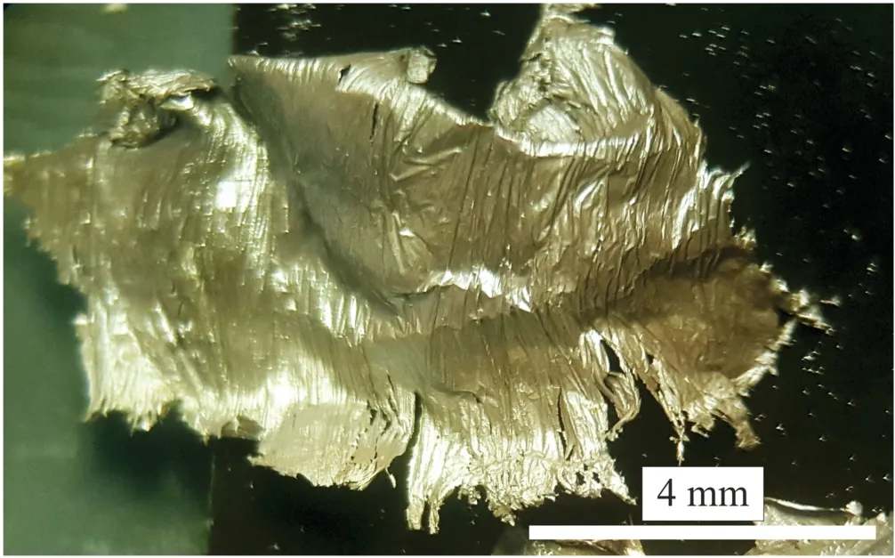
Fig. 3. Macroscopic picture of pure Mg OMO sandwich with a length and width of about 8mm and 6mm, respectively.
The aim of this work is to investigate the characteristics of the dynamically formed oxide films in the unprotected pure magnesium melt using the aforementioned method. The morphology and thickness of these films have been carefully investigated.
2. Experimental method
To generate artificial bubbles in a certain shape and size and blowing them at the predefined time intervals of 2 bubbles per second, a system was designed based on pervious works[21–26] with minor changes described here. In this setup,the compressor produces the compressed air and its pressure reaches the specific value passing through a few instruments including solenoid and control valves. Eventually, the air is introduced to the fluid through a quartz tube with a pressure of 0.2 atm. The internal and external diameter of this tube is 1mm and 3mm, respectively.
As shown in Fig. 1, the casting model is a thin simple plate.The top feeder is designed to postpone the solidification process in order to increase the chance of bubbles entrapment.Apart from that,to prevent solidification of the melt surrounding the quartz tube, a trapezium-shape feeder was designed at the bottom of the plate. A bottom pour gating system was designed and performed to minimize the melt surface turbulence during the filling stage. Reducing the entrance velocity of the melt into the mold was the main concern. The mold material consisted of silica sand, 4%wt. sodium silicate as the binder and 1% dry sulfur powder.
The commercially pure magnesium bars were melted in an electrical resistance furnace. To protect the melt against ignition, MagRex®coverall flux with a grain size of 60 was used. All the tool e.g. crucible, mold, and etc. used in the casting process were preheated up to 100°C. The pouring temperature was 50°C higher than the melting point of the pure Mg.
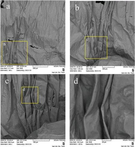
Fig. 4. Backscattered SEM images of OMO sandwich of pure Mg.
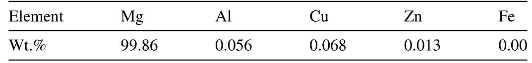
Table 1 Chemical composition of the commercially pure Mg.
Considering Fig. 2, the process of formation of the oxide/metal/oxide samples was done. During melt pouring, the artificial bubbles were released to the mold with specified time intervals. After successfully performing the procedure,the final cast was cooled in the air and cut in pieces. The chemical composition of the sample after the casting process is presented in Table 1.
Eventually, the interfaces of the two entrapped bubbles were carefully taken for the examinations. These samples are called oxide/metal/oxide sandwiches and in the following text,it will be referred as OMO sandwiches. The samples were investigated using X-Ray diffraction (XRD), scanning electron microscopy (SEM) and energy dispersive spectroscopy (EDS)analyses.
3. Results and discussion
3.1. Macroscopic investigations
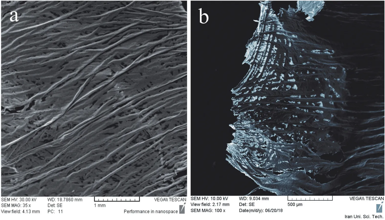
Fig. 5. SEM image of the pure Mg OMO sandwich showing some details of the microstructure. The bright areas in image (b) consists of oxide films and the dark areas are formed as a result of metal entrapment between oxide layers.
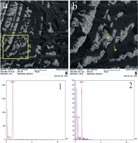
Fig. 6. (a) and (b) SEM pictures of pure Mg OMO sandwich. (1) And (2) are EDS results regarding to the marked points in image (b).
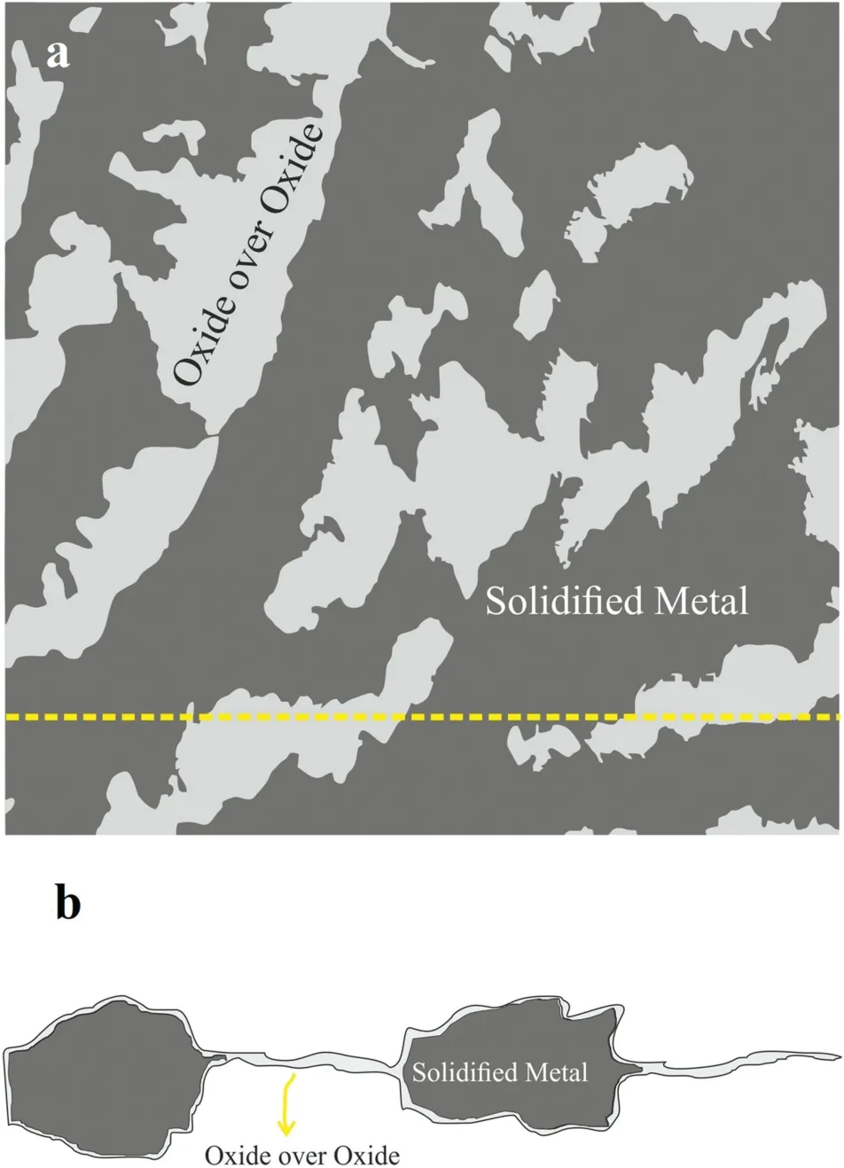
Fig. 7. Schematic views of pure Mg OMO sandwich (a). Top view and (b).Cross-section view of the dashed line in (a).

Fig. 8. XRD pattern of pure Mg OMO sandwich.
Fig. 3 shows a macroscopic image of the shiny surface of OMO sandwich. The average surface size of produced OMO sandwiches was less than 50 mm2. Producing larger OMO sandwiches was not practical since it requires higher blowing pressure. Higher pressure increases the bubble rising velocity,which lowers the chance of its entrapment in the casting.
3.2. Microscopic investigations

Fig. 9. SEM image of the cracks formed on the pure Mg OMO sandwich.Arrows have marked the cracks and teared areas of the sandwich.
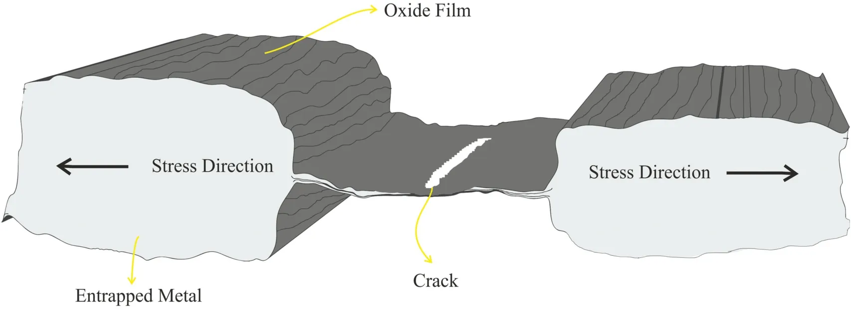
Fig. 10. Schematic for the growth of the cracks in OMO sandwiches.

Fig. 11. Appearance of folds on the surface of pure Mg OMO sandwich.The larger folds have a width range of about 3 to 6μm and the smaller ones are below 1μm in width.
Fig. 4 shows backscattered SEM images of a pure Mg OMO sandwich. It seems a thick oxide film covers the magnesium dendrite’s tip. Several coarse folds and wrinkles can be seen in Fig. 4. The main difference between the morphology of the oxide films formed in dynamic conditions and those formed in a static situation is the presence of such folds and wrinkles [20–24]. Moreover, regarding Fig. 4, in some places on the sandwich’s surface, several discontinuities and micro-cracks are visible. Apparently, OMO sandwich has torn in these locations due to the presence of the mechanical stresses caused by the dynamic motion of the bubbles in the melt. Moreover, shrinkage stresses caused by the difference between the thermal expansion coefficient of magnesium and its covering oxide can be another source.

Fig. 12. Schematics for the re-oxidation of surface in an OMO sandwich.(a). A crack appears on the oxide surface due to the mechanical stress. (b)Opening of the crack, which leads the melt to be exposed to atmosphere. (c)Re-oxidation of the exposed surface and elimination of the crack.
The close view of SEM images of the interface between two entrapped bubbles are presented in Fig. 5. One can see that there is some amount of solidified metal entrapped between two oxide layers. These areas can be seen as the darker and thicker areas in the Fig.5(b).The adjacent brighter regions on the sandwich are the areas in which two oxide layers have touched each other on a dry surface [21,24].

Fig. 13. Formation mechanism of shrinkage folds and wrinkles. The difference in volume reduction of the metal and oxide would be compensated by the formation of folds and wrinkles.
Fig. 6 presents the EDS results obtained from two points marked in Fig. 6(b). Clearly, the intensity of oxygen picks in EDS result of point 2 is relatively high. Besides, presence of the cracks in the bright areas (point 2), indicates that these areas consist of oxide layers, which are overlapped on each other. Thus, it can be confirmed that the dark areas are formed as a consequence of metal entrapment between oxide layers during solidification of the molten metal. As the solidification proceeds, the entrapped molten metal between two oxide layers undergoes a volume shrinkage. Consequently,the solidified metal would be encapsulated at different local points. This creates such a contrast in SEM images. Besides,many folds are visible in SEM micrographs showed in Fig. 5,which are probably formed due to the presence of mechanical stresses [20,24].
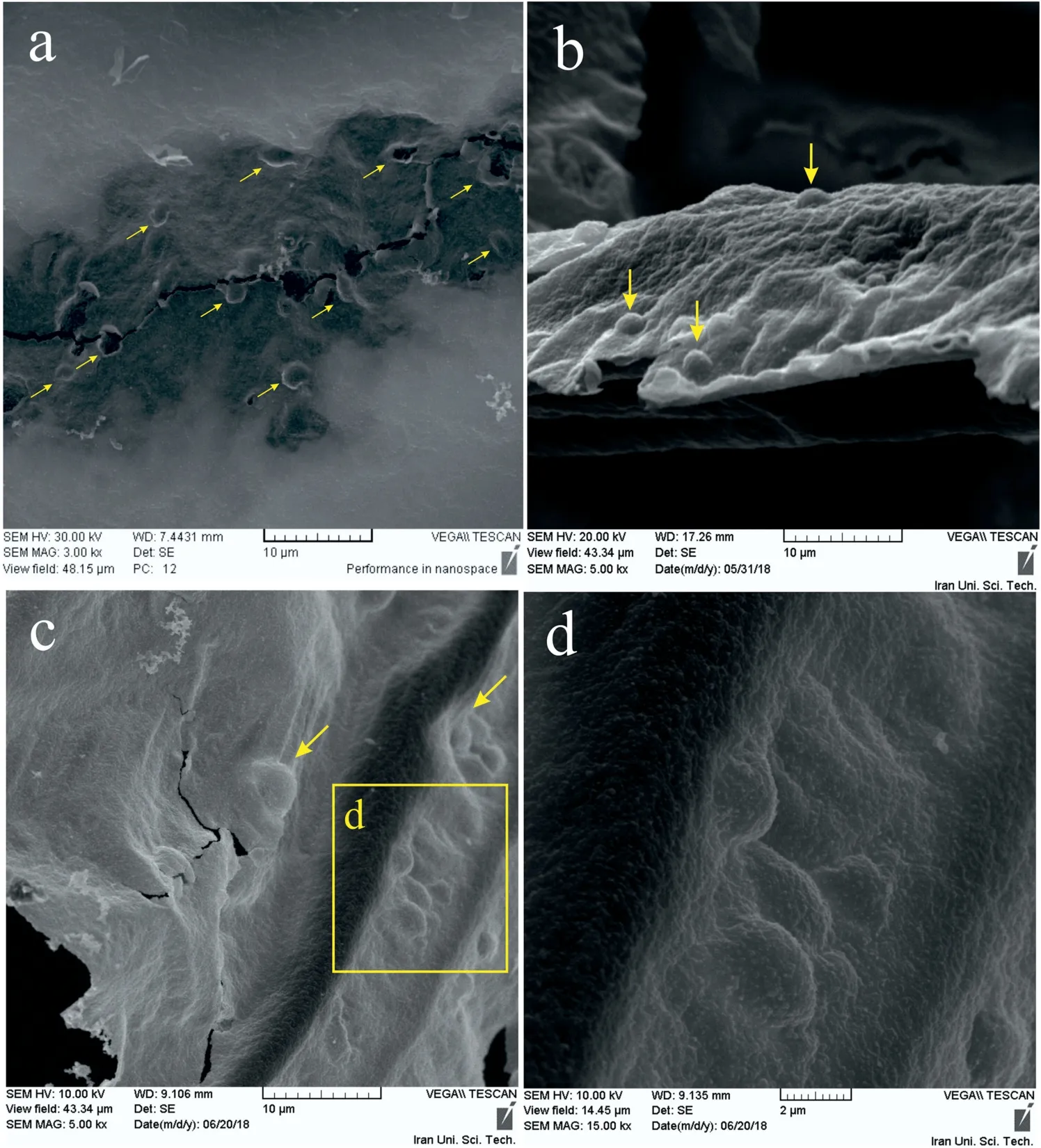
Fig. 14. SEM images showing the blisters on the OMO sandwich surface. Fig. (d) is a magnified picture of the rectangular area marked in (c).
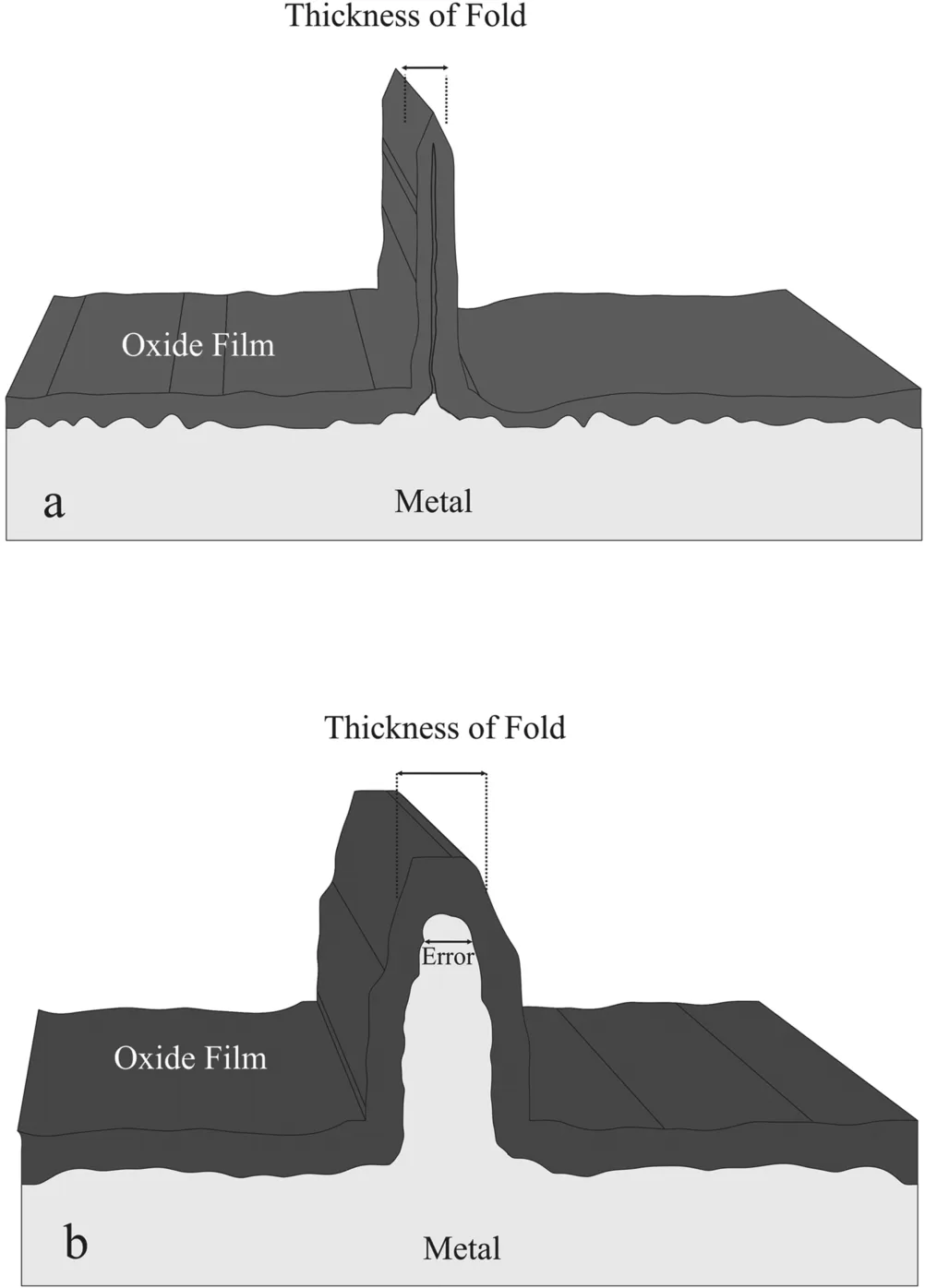
Fig.15. Schematics of folds on OMO Sandwiches.(a)A fold with two oxide surface touching each other (b). A fold with metal entrapment between two layers of oxides, which causes error in the thickness estimation.
Schematic views, top and cross-section, of the pure Mg OMO sandwich is depicted in Fig. 7. The molten metal was suctioned in because of the solidification shrinkage and then entrapped between two layers of oxide. This dual-phase microstructure has also been observed in aluminum and zincbased alloys [20,23–25]. In the case of Al alloys, the contrast of these two phases is more noticeable in SEM images [24].The lower thickness of the amorphous oxide films formed on molten Al alloys can be the reason behind.Moreover,in comparison to the dynamically formed oxide films of Al alloys,Mg-based alloys form a less wrinkled oxide film [23,25].
The XRD pattern of the sandwich is presented in Fig. 8.The majority of the peaks are related to pure Mg. However,few peaks,which are attributed to the MgO,are also observed in the XRD pattern. The low amount and thickness of the oxide formed on the sandwich are the reasons behind the low intensity of the MgO oxides peaks.Regarding the XRD result,it can be concluded that short time oxidation of the molten pure Mg led to the formation of the crystalline MgO.
As illustrated in Fig. 9, a closer look at the SEM images taken from the sandwiches, indicates the higher probability of crack formation in places where two oxide layers are in touch.The oxide films are brittle in nature and cannot be as flexible as metals facing mechanical stresses. Areas where two oxide layers are directly in contact and those with the minimum entrapped metal are more inclined to host the crack. Thisconcept is schematically depicted in Fig. 10. If the oxide film is thin, about a few nanometers, the forces and stresses will be exerted on the film in only two directions.
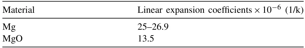
Table 2 Linear expansion coefficients for Mg and MgO at room temperature [27].
The presence of the folds in different sizes is the most significant feature of the dynamically formed oxide films in the case of pure Mg. Folding of the oxide films may occur either above or below the melting point of the metal. Thus,the folds can fall into the two categories, (a) those that form above the melting point including folds and wrinkles and (b)those that form below the point which are only wrinkles. The width of the folds is greater than the wrinkles [25].
As shown in Fig. 11, smaller folds have formed within the areas between the bigger folds. Re-oxidation of the surface oxide film is the reason behind such a morphology. Considering Fig. 12, tension stresses exerted on the oxide film leads it to be torn. By increasing the size of the crack, the molten metal, which has been entrapped in the OMO sandwich,would be exposed to the atmosphere of the bubbles.The fresh and uncovered melt would be immediately re-oxidized and the crack will be sewn. These freshly formed films are very thin comparing to the old oxide layers. In addition, one can see that folds and wrinkles on the oxide layer are formed in the same direction. Since the direction of the stress which has caused the oxide films to be cracked, is still the same,the new oxide film experiences it with the same axis. Thus,the arrangement of the folds and wrinkles formed on the new oxide layers remains constant. Moreover, due to the lower thickness of the new oxide film, the wrinkles are also smaller than those on the older film are.
Mechanical stresses during formation of the OMO sandwich are one of the main sources for the generation of folds [20]. The high-velocity upward motion of the bubbles,pressure difference between them and turbulence of the melt surrounding the bubbles can cause mechanical stresses.Formation of the large folds and wrinkles is to be expected due to such stresses [20]. The magnitude of this stress is high enough to deform the entrapped metal between the oxide layers and fold it. Moreover, the mechanical stresses lead to the formation of large cracks in some areas of the OMO sandwich. Table 2 presents the values of the linear expansion coefficient for the Mg and MgO at room temperature. The difference between the volumetric thermal expansion of the MgO film and Mg metal is another source of stress.
The formation mechanism of the shrinkage folds and wrinkles is schematically shown in Fig. 13. Decreasing temperature causes both the entrapped metal and oxide film to shrink.As illustrated in Fig. 13(b), the substrate metal experiences a greater reduction in volume compared to the shrinkage of oxide film.Consequently,the folds and wrinkles would be appeared on oxide film to compensate the difference between the surface area of the film and substrate. The Shrinkage forces act on the OMO sandwich in all directions. Therefore, wrinkles can form in different directions on the OMO sandwich.

Fig. 16. Estimation of the oxide thickness by measuring the width of the folds in SEM images from different areas of OMO sandwich. The images (b) and(d) are the magnified images of the marked area in images (a) and (c), respectively.
The swells or blisters found on the oxide layers are other notable features of the pure Mg OMO sandwich.Fig. 14 shows some of these swells from different views.Three possible mechanisms can cause the surface swelling or blisters on the oxide films. The first mechanism can be based on the entrapment of the gaseous hydrogen molecules under the oxide skin. Hydrogen is the only gas, which can be dissolved in Mg melt. The maximum solubility of hydrogen in liquid and solid states of magnesium is 27 and 19 cm3per 100g, respectively [28]. Molten Mg rejects only 32% of its hydrogen content while in the case of Al this value is about 95% [29]. This implies the higher rejection of hydrogen in Al melt than Mg [29,30]. Anyway, the extra amounts of the dissolved hydrogen atoms in the melt would be rejected during the solidification process. These rejected atoms join each other and form the molecular hydrogen.The molecular hydrogen can be entrapped under the oxide skin and create blisters on the OMO sandwich.The second explanation for the formation of the blisters can be attributed to Mg vapor. The vapor pressure of the molten magnesium in the atmosphere is equal to 1 atm [31]. Therefore, there is a chance for the presence and entrapment of the Mg vapors under the oxide layers. In other words, the vaporization of the entrapped molten Mg can be one of the sources for the formation of blisters. The third mechanism which sounds more conservative and acceptable among other mechanisms is the oxide film defect. The first and second mechanisms suggest creating a hollow swell.
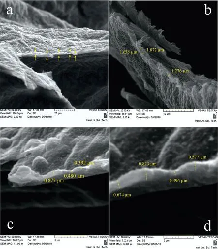
Fig. 17. Thickness estimation of the oxide layer by measuring the width of the edge layer in SEM images of pure Mg OMO sandwich.
However,regarding Fig.14(d),there is no evidence to confirm the hollowness of swells.
3.3. Thickness estimations
A simple method to estimate the thickness of the dynamically formed oxides is to measure the width of the folds and wrinkles formed on the OMO sandwiches. By halving the width of these folds, an approximate thickness for the oxide film would be achieved. However, considering Fig. 15 entrapment of the melt reduces the accuracy of the estimation. Accordingly, not every fold would be suitable for this measurement.
The thickness of the oxide film which measured using folds shown in Fig. 16(a,b), is determined to be about 700nm. Researchers have reported values about 2.5μm for the dynamic oxide film formed on the AZ91 Mg alloy melt using the same method [20]. Fig. 16(c,d) shows thickness estimation of the oxide films which formed because of the re-oxidation or selfsewing phenomena. This type of oxide film formed on the pure Mg, as discussed before, has a very limited time to grow and evolve.The re-oxidation phenomenon causes formation of newer and thinner oxide films so that the width of the folds formed on these new and thin oxide films is lower than that of older oxide films. The estimated thickness of this film is in the range of 400nm to 450nm, which is about half the thickness of the old films. The oxide film formed on the Mg alloys melt is relatively thick and rough. The presence of the macroscopic and microscopic folds provide the possibility of air entrapment in the bifilms.
In comparison to the compact and protective oxide layer formed on the Al alloys melt, the thicker and rougher oxide films on the Mg alloys require more attention. The Weibull modulus of the Mg alloys, at the same conditions, is lesser than the Al alloys [32]. The reduction in mechanical properties of the Mg cast parts due to the presence of the oxide films depends on the morphology, thickness and probably distribution of these films in the melt and final casting [19,20,33].
Measuring the thickness of the OMO sandwich at the edges is another way to estimate the oxide film thickness,eliminating the error caused by metal entrapment in the folds. Fig. 17 shows the SEM images taken from the edge of the pure Mg OMO sandwiches. By halving the acquired values, the film thickness is estimated from 200 to 800nm.The scattered values for the oxide film thickness indicate that the complex conditions for the oxide formation have caused the thickness of the film to be varied in different areas of the films. Considering the type of the oxidation process, i.e.dynamic or static, and the method used for estimating the thickness of the film, different values have been reported in the literature. Entrapment of the oxides in the melt due to the surface turbulence happens very fast so that theses entrapped oxides have very short times to thicken. For this reason, the thickness of these films is in the range of a few hundreds of nanometer [34].
4. Conclusion
In the present study, the oxide films formed on the pure Mg melt in dynamic conditions were investigated using Oxide/Metal/Oxide (OMO) method. Following results were concluded:
(1) The pure Mg OMO sandwiches were shiny in appearance and their average size was less than 50 mm2. The SEM images and EDS analyze showed that the pure Mg OMO sandwiches consist of two different areas, which were distinguished by the image contrast, overlapped oxide layers and metal entrapment regions.
(2) A lot of folds,wrinkles,and cracks found on the surface of OMO sandwiches. Many factors such as mechanical stresses and difference in thermal expansion coefficients between the metal and oxide are the source for the formation of such a microstructure.
(3) Based on the SEM images and XRD patterns, the oxide films formed in these conditions were rough,porous and crystalline in the microscopic level which implies the non-protective behavior of the oxide film.
(4) The thickness of the oxide film was estimated using two methods. In the first method, the half width of the folds formed on OMO sandwich is reported as the film thickness. Using this method the thickness of the old oxide was estimated to be about 700nm.Also,the thickness of the new oxide which is formed due to the re-oxidation phenomena was determined in the range of 400nm to 450nm. In the second method in which the thickness of the OMO sandwich edges is measured, the range of oxide film thickness was estimated to be between 200nm and 800nm.
Declaration of Competing Interest
None.
杂志排行

Journal of Magnesium and Alloys的其它文章
- Influence of trace As content on the microstructure and corrosion behavior of the AZ91 alloy in different metallurgical conditions
- Active corrosion protection of super-hydrophobic corrosion inhibitor intercalated Mg–Al layered double hydroxide coating on AZ31 magnesium alloy
- Graphene nanoplatelets-reinforced magnesium metal matrix nanocomposites with superior mechanical and corrosion performance for biomedical applications
- The role of recrystallization and grain growth in optimizing the sheet texture of magnesium alloys with calcium addition during annealing
- Fatigue strength evaluation of self-piercing riveted joints of AZ31 Mg alloy and cold-rolled steel sheets
- Corrosion fatigue of the extruded Mg–Zn–Y–Nd alloy in simulated body fluid