Fatigue strength evaluation of self-piercing riveted joints of AZ31 Mg alloy and cold-rolled steel sheets
2020-04-29SeHyungKngDongWoonHnHoKyungKim
Se-Hyung Kng, Dong-Woon Hn, Ho-Kyung Kim
a Graduate School, Seoul National University of Science and Technology, Seoul, 01811, South Korea
b Department of Mechanical and Automotive Engineering, Seoul National University of Science and Technology, Seoul, 01811 South Korea
Abstract The application of magnesium alloys to automobiles is increasing due to their superior specific strength and specific stiffness. In this study, an upper sheet of AZ31 magnesium alloy and a lower sheet of cold-rolled steel were joined by self-piercing riveting (SPR), a method commonly used to join automotive panels. A cross-shaped specimen was fabricated with a punching force of 35kN, which exhibited the best joint strength for the SPR joint specimen geometry. Monotonic and fatigue strengths were evaluated using cross-shaped specimens at loading angles of 0°, 45°, and 90°. The load amplitude corresponding to the fatigue endurance limit was assumed to be at 106 cycles, and the fatigue ratios (= fatigue endurance limit/static strength) at the loading angles of 0°, 45°, and 90° are 22%, 13%, and 9%, respectively.For all three loading angle specimens, fatigue cracks initiated at the triple point where the rivet shank, the upper sheet and the lower sheet are in contact with each other, with the cracks propagating through the thickness of the upper sheet and ultimately leading to fracture. The fatigue lifetimes were evaluated through the von-Mises stress, maximum principal stress, and equivalent stress intensity factor. It was found that the fatigue lifetimes could be evaluated most appropriately through the maximum principal stress.
Keywords: Self-piercing riveting; Magnesium alloy; Fatigue strength; Maximum principal stress; Fatigue lifetime.
1. Introduction
Magnesium alloys have superior specific strength and specific modulus as well as excellent vibration damping capacities. These advantages make it possible to achieve weight reductions in automotive bodies and ride comfort simultaneously. Therefore, the use of magnesium alloys to create automobile components is increasing [1,2]. When joining two plates in automotive industry, electric resistance spot welding is generally used. Spot welding has several advantages,including a short welding time, relatively low thermal deformation after welding, and excellent welding quality. However, in order to join dissimilar metal sheets such as steel and magnesium alloys, spot welding becomes challenging due to difference in melting temperatures, electric resistance levels and metal crystal lattice.
SPR method, as a substitute for resistance spot welding,has been used to join aluminum sheets to each other and to join aluminum and steel sheets.SPR is a type of cold-forming technique which forms a strong mechanical interlock between two or more sheets. This locking mechanism is formed by means of a semi-tubular rivet, which, pressed by a punch,pierces the upper sheet and flares into the lower sheet without breaking the lower sheet, as shown in Fig. 1. The SPR method is advantageous in that it does not require any additional materials other than the rivet. SPR does not generate harmful substances, is an eco-friendly process, and offers excellent joining capabilities [3,4].
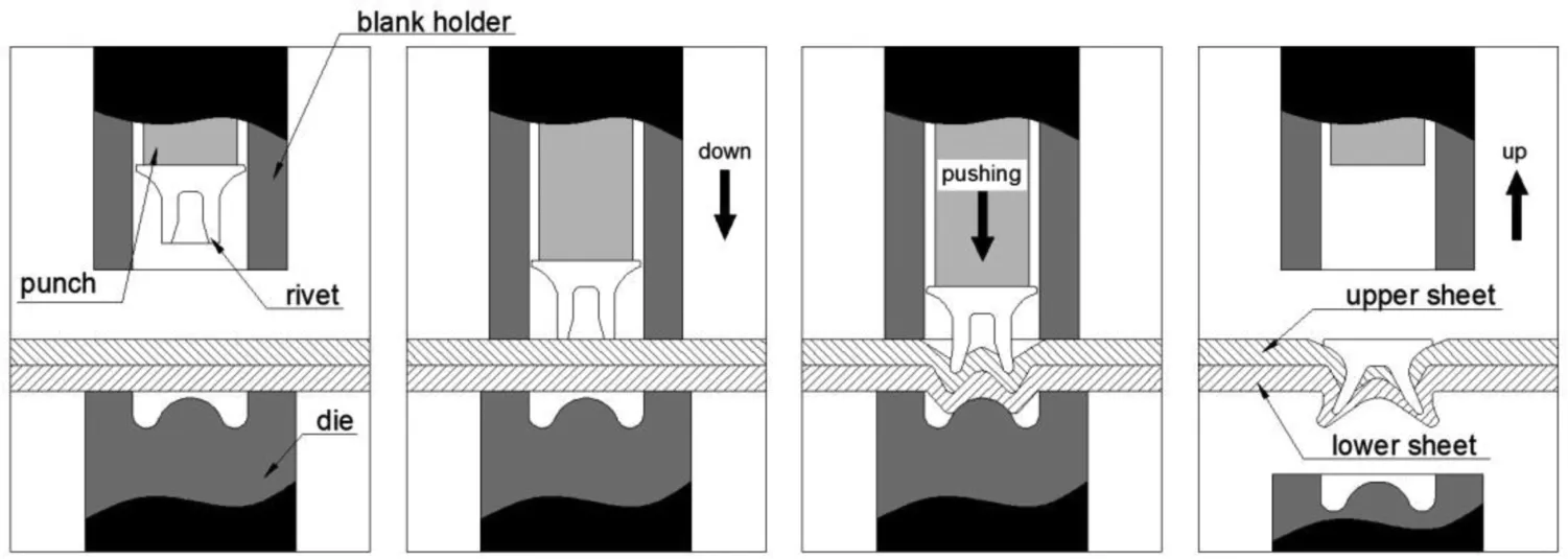
Fig. 1. An illustration of the self-piercing riveting process.
There have been several published results [5–12] on the fatigue behavior of SPR joints of aluminum alloys. However, researches on applications of the SPR joining method to magnesium alloys has been very limited [13–19]. For example, Luo et al. investigated the application of the SPR technique to join aluminum extrusion parts to magnesium die castings and stamped sheets of aluminum to quick-plasticformed magnesium sheets [13]. They conducted static tests using tensile-shear specimen geometry and reported that the combination of magnesium casting sheet placed on top of an aluminum extrusion sheet led to higher joint strength. Kang et al. investigated the fatigue performance of laser assisted self-piercing rivet joints for magnesium alloys using tensileshear and coach-peel specimens [14]. They found that the outcomes from a structural stress method developed for spot welding were well correlated with fatigue test results. Wang et al. studied the SPR joining conditions of AZ31 magnesium alloy sheets [15], finding that the lower sheet became defective during the SPR joining process at room temperature. They proposed Zener–Hollomon parameter to evaluate the effects of the preheating temperature and strain rate on the strength and elongation of magnesium alloys. They also reported a suitable preheating temperature range and strain rate for the SPR joining of the alloy in their study of 453 ∼473K and 4 s−1. Durandet et al. investigated the laser-assisted selfpiercing riveting (LSPR) of magnesium sheets [16], finding that when joining these sheets at low to intermediate temperatures, cracking occurs in shear-deformed zones where strain localization occurs due to limited dynamic recrystallization.Cracking could be prevented by laser preheating to a temperature higher than 473K. They reported that the strength of the SPR joint is influenced by the length and hardness of the rivet. Miyashita et al. investigated the static and fatigue strengths of SPR and adhesive-aided SPR joints of AM50 magnesium alloy sheets using the tensile-shear specimen geometry [17]. They reported that the monotonic and fatigue strengths of adhesive-aided SPR joints were higher than those of SPR joints. Upadhyay et al. undertook the electrochemical characterization of coated rivets for magnesium alloys[18]. They utilized three types coating on the steel rivets and conducted electrochemical measurements of the coated rivet samples. They compared the efficacy of various rivet coatings in suppressing galvanic corrosion in magnesium-containing structures. Silva et al. studied the galvanic corrosion of SPR joints of AZ31 magnesium alloy and Al-5083 aluminum alloy[19]. They conducted an immersion test to confirm the degree of corrosion of the coated rivets, the upper magnesium alloy sheet and the lower aluminum alloy sheet. They derived a function of the corrosion potential and the adsorption rate and reported that the rate of corrosion could be predicted using this function.
The evaluation of the fatigue strength of the magnesium SPR joints is of great importance in order to evaluate the fatigue strength of a vehicle body when the SPR joining method is applied to the body composed of magnesium and steel sheets. However, there are few studies of the fatigue strengths of SPR joints of magnesium alloys and/or dissimilar materials.In particular, there are especially few studies of the fatigue strength of SPR joints of magnesium alloys and steel sheets under various loading conditions. Therefore, in this study,cross-shaped SPR joint specimens consisting of AZ31 magnesium alloy and SPCC (steel plate cold commercial) were subjected to 0°, 45°, and 90° loading angles to determine the monotonic strength and fatigue strength. Based on the experimental results, various fatigue strength parameters were evaluated to determine fatigue lifetimes. Based on this, we determined the parameters for appropriately evaluating the fatigue strength at various loading angles of magnesium SPR joints.
2. Experimental
2.1. Specimen materials and preparation
In this study, AZ31 magnesium alloys and SPCC, which are mainly used as steel sheets for body frames, were applied for the SPR joint specimens. Generally, when two different materials are joined by SPR, a higher level of stress is generated in the lower sheet. Therefore, it is advantageous to utilize a relatively high-strength material for the lower sheet in view of the static strength [20]. Therefore, the specimens consist of SPCC with higher strength as a lower sheet and AZ31 magnesium alloy as an upper sheet. The shape and dimensions of the specimen and loading direction are shown in Fig. 2. Monotonic and fatigue tests were carried out on the cross-shaped specimen shown in Fig. 2 at various loading angles. Each data point except for the fatigue strengths is the average value from three specimens.
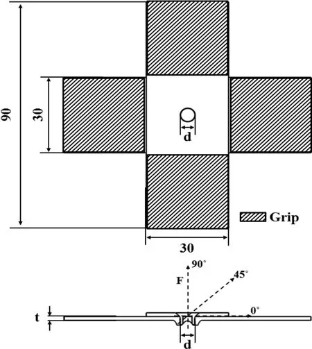
Fig. 2. Geometries and loading directions of cross-shaped SPR specimens.

Table 1 Tensile properties of the AZ31 magnesium alloy and SPCC [21].
2.2. Evaluation of the mechanical properties of AZ31 alloy
The tensile specimens shown in Fig. 3 were prepared to determine the mechanical properties of the magnesium alloy sheet in the rolling direction and transverse direction. In the tensile test, the cross-head speed was 3mm/min, corresponding to the strain rate of 8.3×10⁻⁴s−1. The stressstrain curves of two specimens in the rolling direction and transverse direction are shown in Fig. 4. Table 1 summarizes the mechanical properties of the AZ31 magnesium alloy obtained through the tensile tests. In the tensile test, the tensile strengths of the specimens in the rolling direction and in the transverse direction were found to be similar at approximately 277MPa. The yield strength is also similar at approximately 147MPa in both directions. On the other hand, the elongation at failure of the specimen in the transverse direction was close to 10%, which is nearly 0.6 times lower than the rolling direction outcome. As a result, the tensile and yield strengths are considered to have no significant effect according to the rolling direction and only a slight effect in terms of elongation at failure. The SPCC experimental data were sourced from earlier work [21].
2.3. Monotonic and fatigue tests
For the monotonic and fatigue tests of the cross-shaped SPR specimen at loading angles of 0°, 45° and 90°, a special fixture, as shown in Fig. 5, was applied. This fixture is similar to the fixture for spot weld joint proposed by Lee et al. [22]. The detailed loading fixture of the specimen is available in the literature [23]. To evaluate the monotonic and fatigue strengths of the SPR joints,a servo hydraulic universal testing machine (Instron 8516) was used. The diameter and length of the shank of the rivet used in this study are both 5.3mm,and the thicknesses of the sheets of AZ31 magnesium alloy and SPCC are 1.5mm. For the combination in the SPR joint, the SPR consists of a SPCC sheet with relatively high strength as the lower sheet. On the other hand, in the SPR joining method, the joint strength is determined by the shape of the rivet, the thickness of the sheet material, the piercing direction, and the rivet punching force. Therefore, SPR joints were prepared by various punching forces to determine the optimum joint strength. The fatigue test utilized a sine wave form with a load ratio (R=Pmin/Pmax) of 0.1.
2.4. Structural analysis modeling
The cross-section of the SPR joint specimen produced with the optimal punching force is shown in Fig. 6. 3D finite element modeling of this joint was conducted using the HyperMesh program. For the three-dimensional finite element model, as shown in Figs. 7 and 8, an eight-node hexahedral element (C3D8R) was used. There were 74,943 nodes and 63,456 elements. A contact pair function was used to model the contact surfaces. The coefficient of friction between materials was determined experimentally. The friction coefficients between the magnesium alloy and the steel sheets and between the steel sheets were 0.374 and 0.25, respectively. A finite element analysis was conducted using the ABAQUS solver.
3. Results and discussion
3.1. Optimum punching force for SPR joining
During the SPR joining of two different material sheets,the joint features differ according to the punching force.When the punching force is relatively low, the rivet head tends not to come fully contact with the upper sheet. If the punching force is too strong, excessive plastic deformation of the lower sheet occurs due to the rivet such that the upper and lower sheets are distorted and the rivet head sinks into the upper sheet. Therefore, in order to confirm the punching force with the optimum joint strength at a load angle of 90° for the cross-shape specimen,specimens were prepared under various punching forces. Fig. 9 shows the joint strengths of the specimens prepared using various punching forces. The punching force with the highest joint strength was found to be 35kN,with the rivet properly pierced without excessive plastic deformation. Therefore, the specimens for the monotonic strength and fatigue strength tests were prepared at a punching force of 35kN.

Fig. 3. Shape and dimensions of the tensile specimen for AZ31 magnesium alloy.
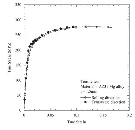
Fig.4. Stress-strain curve for the tensile specimen of AZ31 magnesium alloy in the rolling and transverse directions.
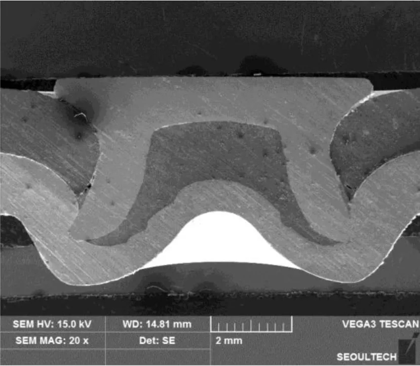
Fig. 6. Cross-section from the center of the SPR joint.
3.2. Monotonic strengths of SPR joints
In order to investigate the influence of the rolling direction of the AZ31 magnesium alloy sheet on the monotonic strength, the upper magnesium alloy sheets of the test specimens were prepared in two ways, as shown in Fig. 10. The first was with the rolling direction parallel to the loading direction and the second was with the transverse direction perpendicular to the loading direction. Monotonic tests were performed at loading angles of 0°, 45°, and 90°.
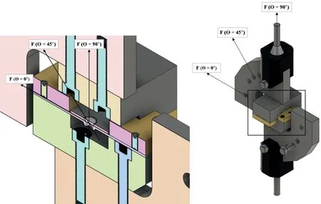
Fig. 5. Loading angle fixture for the SPR joint.

Fig. 7. Cross-section view of the SPR joint in the FEA model.
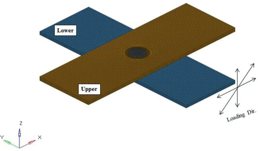
Fig. 8. 3-D FEA model of the SPR joint.
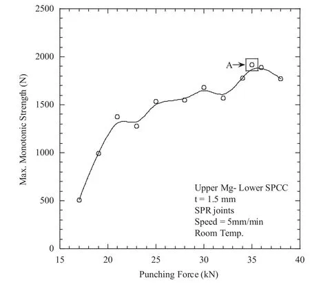
Fig. 9. Punching force against the maximum monotonic strength for crossshaped SPR joints with the combination of an upper AZ31 magnesium alloy sheet and lower SPCC sheet.
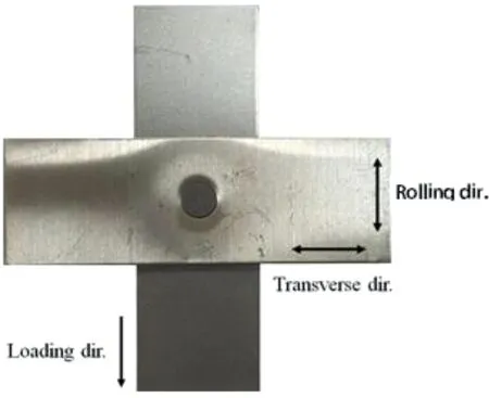
Fig. 10. Definition of rolling and transverse directions to the loading direction.

Table 2 Monotonic test results of the SPR specimens with respect to the rolling direction at different loading angles.
Fig. 11 shows the monotonic test results. Both specimens showed the highest monotonic strength when the loading angle was 0°and the lowest strength when the loading angle was 90°. In other words, the cross-shaped specimen is shown to be more vulnerable to the separation of the rivet roots from the lower sheet due to bending moment with tensile force compared to the separation of the rivet from the lower sheet due to shear force.
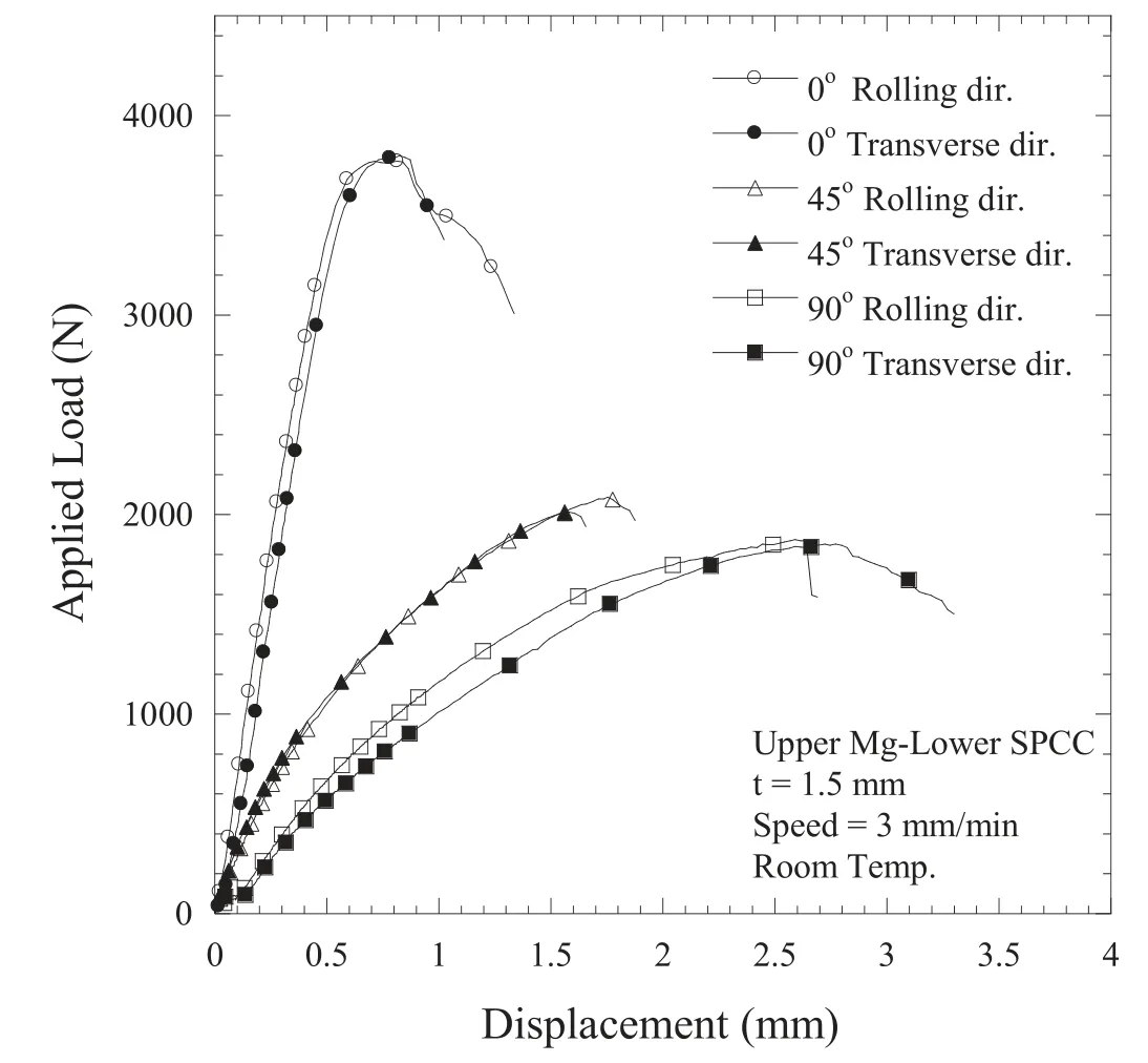
Fig. 11. Comparison of the static load versus the displacement curves of SPR specimens according to rolling direction at different loading angles.
Table 2 summarizes the monotonic test results of the SPR specimen with respect to the rolling direction of the magnesium sheet at each loading angle. The rolling direction and transverse direction are parallel and perpendicular to the loading direction, respectively, as defined in Fig. 10. The maximum static loads of the specimens in the rolling direction and transverse direction at the loading angle of 0° were 3771N and 3764N, respectively. The failure displacement in the rolling direction was approximately 35% higher than that in the transverse direction. At a loading angle of 45°, the maximum static loads of the specimens in the rolling direction and in the transverse direction were 2094N and 2009N,respectively. It could be confirmed that the static strengths of the SPR joint at loading angles 0° and 45° were not affected by the rolling direction of the upper magnesium sheet. For a loading angle of 90°, the specimens in the direction transverse to the load direction had a static strength of 1857N,which was approximately 9% higher than that of 1710N in the rolling direction. In addition, the failure displacement of the specimen in the rolling direction was approximately 23%higher than that of the specimen in the transverse direction.Therefore, it was confirmed that the rolling direction of the upper magnesium alloy sheet had a slight influence on the static strength of the SPR joint specimen at a loading angle of 90°.
3.3. Fatigue strength evaluation of SPR joints
The fatigue test was carried out on the specimens at loading angles of 0°, 45°, and 90°. For the upper magnesium alloy sheet of the fatigue specimens, the rolling direction of the sheet was perpendicular to the loading direction. The fatigue test results are summarized in Table 3. Fig. 12 shows the load amplitudes and fatigue lifetimes of the specimens at loading angles of 0°, 45° and 90°. For load angle of 0°, 45°,and 90°,the corresponding relationships between the load amplitude and the number of cycles were Pamp=,Pamp=, and Pamp=1617.3. For a loading angle of 0°, assuming a fatigue endurance limit at 106cycles, the load amplitude corresponding to the fatigue limit is 824N, corresponding to approximately 22% of the static strength (P=3774N). For loading angle of 45° and 90°, the load amplitude corresponding to the fatigue limit is 257N and 168N, which corresponds to approximately 13% and 9% of the static strength, respectively.
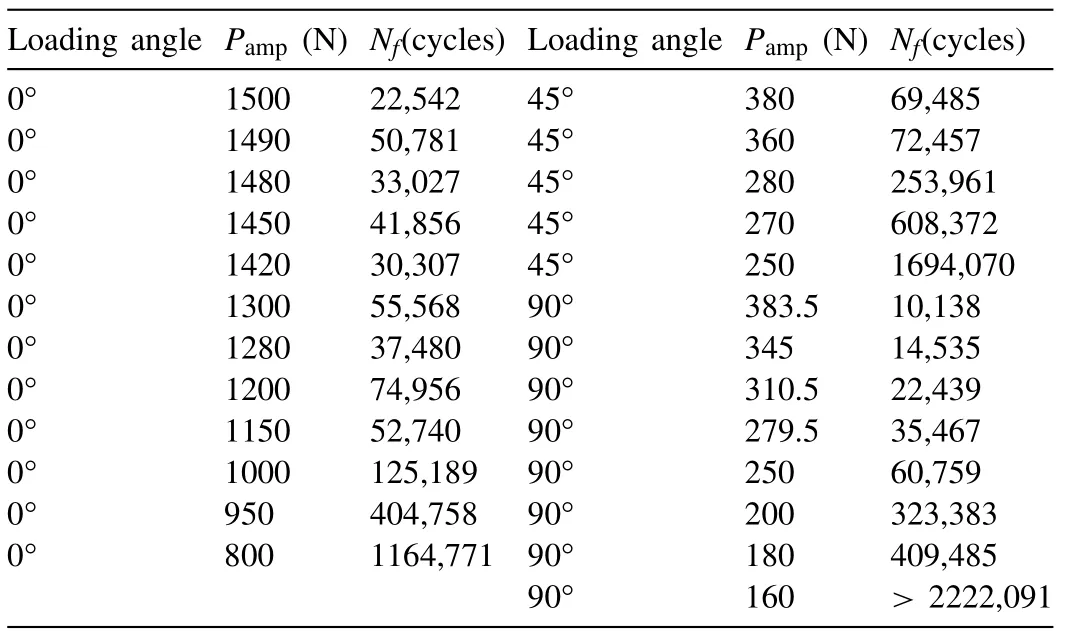
Table 3 Summarized fatigue test results.
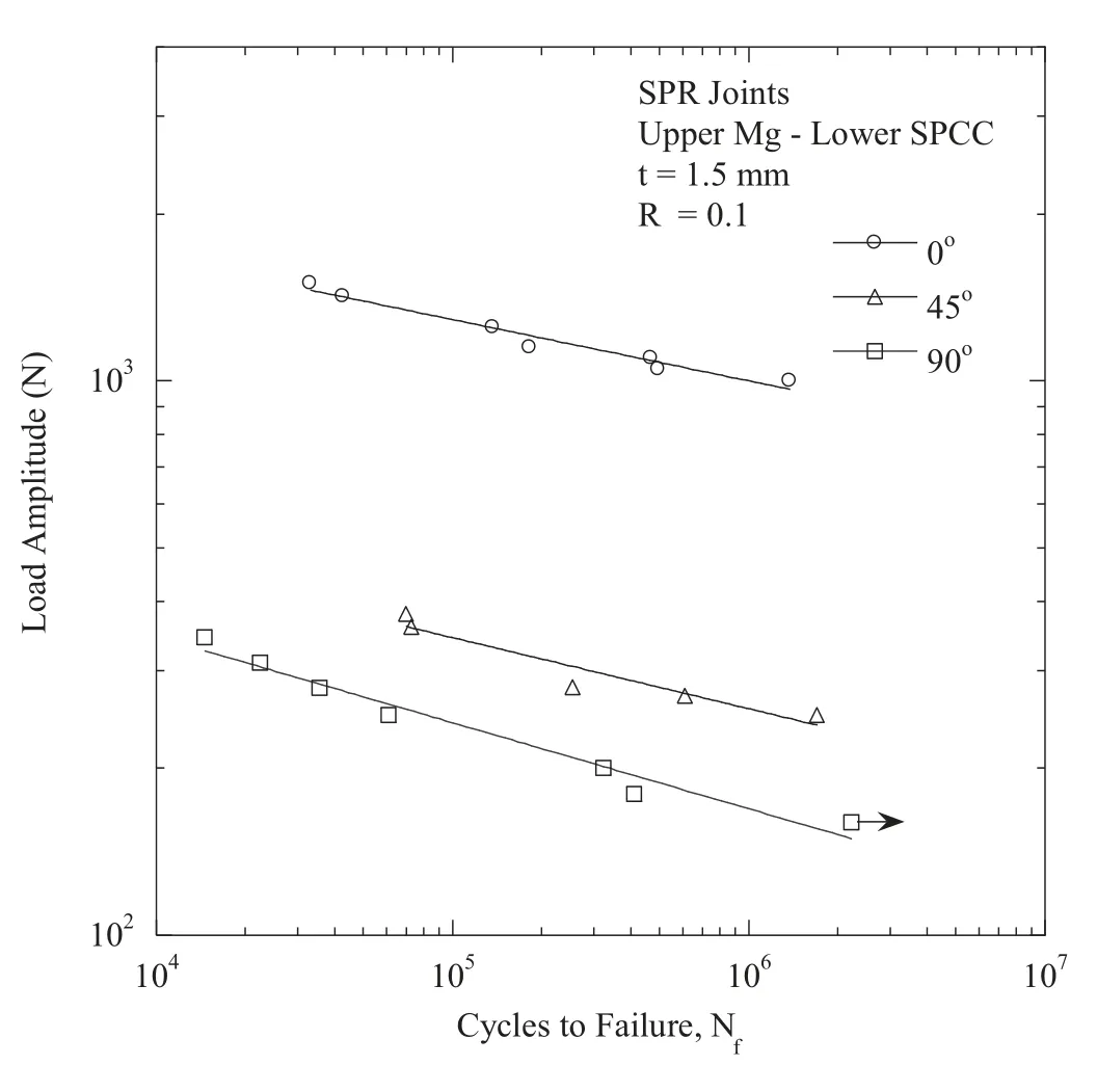
Fig. 12. Plot showing the results of a comparison of the load amplitude against the number of cycles to failure for SPR joints at different loading angles.
3.4. Fatigue failure mode
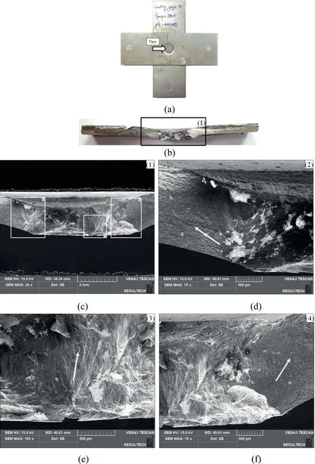
Fig. 13. Fatigue fracture surfaces of the specimen under Pamp=180N at θ=90°: (a) front view, (b) fractured surfaces view, (c) enlarged local area marked as (b), (d), (e), and (f) enlarged local areas marked as (2), (3), and (4) in Fig. (c), respectively.
The fatigue test specimens exhibited crack initiation and fracturing of the upper magnesium alloy sheets at three loading angles.The fracture surfaces of the fatigue specimen were observed using a scanning electron microscope (SEM, Model TESCAN VEGA3) in order to confirm the crack initiation sites and growth direction in the fatigue specimen. Fig. 13 shows the fracture mode of the specimen under a load amplitude (Pamp) of 180N for a loading angle of 90°. The fatigue lifetime of this specimen is 409,485 cycles.For this specimen,cracks were observed in the upper magnesium alloy sheet, as shown in Fig. 13(a) and (b) shows the fatigue surfaces of the upper sheet viewed from the indicated “view direction”in Fig. 13(a) and (c) is an enlarged view of Fig. 13(b) toidentify the crack initiation sites and growth direction in the specimen. Fig. 13(d) is an enlarged photograph of area (2)shown in Fig. 13(c). It is considered that the crack initiated at the triple point where the upper and lower sheets and the rivet all converge. The direction of the arrow shown in Fig. 13(d)indicates how the cracks propagated. It was observed that the surfaces were partially oxidized in the vicinity of the joint of the rivet and the upper sheet, an outcome considered to be due to fretting wear. Fig. 13(e) shows an enlargement of area(3) in Fig. 13(c). It could be confirmed that a crack initiated at the point where the rivet and the upper sheet meet. It is assumed that the initiated cracks propagated in the direction of the rivet head as indicated by the arrow shown in Fig. 13(e)and (f), an enlargement of area (4) shown in Fig. 13(c), confirms that the crack propagated in the direction of the arrow shown. Hence, cracks at the loading angle of 90° initiated at the triple point where the rivet shank is in contact with the upper and the lower sheets and propagated through the thickness of the upper sheet, with a fracture finally occurring when they pass around the rivet.

Table 4 Summarized structural analysis results of the upper sheets under the maximum load corresponding to a fatigue lifetime of 106 cycles at three different loading angles.
3.5. Structural analysis results
A finite element analysis was carried out on SPR joints at loading angles of 0°, 45°, and 90°. Typically, stress is more concentrated on the lower sheet when various loads are applied to the cross-shaped SPR joint specimens. As shown in Fig. 13, fatigue crack initiation occurred and the magnesium alloy sheet fractured given its relatively lower strength. Thus,the structural analysis results pertain to the upper sheet of this specimen. Table 4 summarizes the magnitudes and locations of the maximum value of the von-Mises (σeq) and maximum principal (σ1) stresses in the analysis results. Fig. 14 shows a typical analysis result when the maximum load (Pmax) was 373N at a load amplitude of 168N and at a load ratio R=0.1 corresponding to a fatigue lifetime of 106cycles at a loading angle of 90°. Fig. 14(a) shows the von-Mises stress distribution. It was confirmed that maximum stress of 163MPa occurred at the triple point where the upper sheet, the lower sheet and the rivet shank are in contact with each other. As a result, it was confirmed that the location of maximum stress on the upper sheet of the SPR joint is similar to the crack initiation location of the fatigue specimen at a loading angle of 90°. Therefore, crack initiation occurred at the point where the von-Mises stress value was maximized, with the cracks then propagating through the thickness of the upper sheet,leading to the final fracture while passing around the rivet.Fig. 14(b) shows the maximum principal stress distribution.It was confirmed that the maximum value of 170.0MPa occurred at the point where the upper and the lower sheets were in contact.
3.6. Fatigue lifetime evaluation of SPR joints
Fatigue lifetimes of the cross-shaped SPR specimens at loading angles of 0°, 45°, and 90° were evaluated using the von-Mises stress (σeq) and maximum principal stress (σ1).These results are shown in Fig. 15(a) and (b), respectively.The maximum principal stress is appropriate for evaluating the fatigue lifetime. In addition, the fatigue lifetimes of the specimens were evaluated by applying the equivalent stress intensity factor of spot-welded specimens as proposed by Zhang[24].
Zhang [24] defined the equivalent stress intensity factor of a spot-welded specimen with respect to the loading angle.This is expressed by Eq. (1),

where F is the applied load and θ is the applied loading angle. d is the nugget diameter, which corresponds to the rivet diameter of 5.3mm in this study. t is the specimen thickness of 1.5mm and b is the specimen length of 30mm at the junction of the upper and lower sheets of the joint. ξ is determined by the shape of the specimen as a correction factor[24]. The correction factor ξ for the cross-shaped specimen in this study was determined to be 1.19.
For loading angle 0°, Eq. (1) becomesand for loading angle of 90°, Eq. (1) becomes Keq=On the other hand, when the loading angle is 45°, the specimen undergoes tensile and shear forces simultaneously. That is, the tensile and shear forces are respectively Fsin45° and Fcos45°, i.e., 0.707F. Therefore, the equivalent stress intensity factor for the loading angle of 45° is defined by Eq. (2).

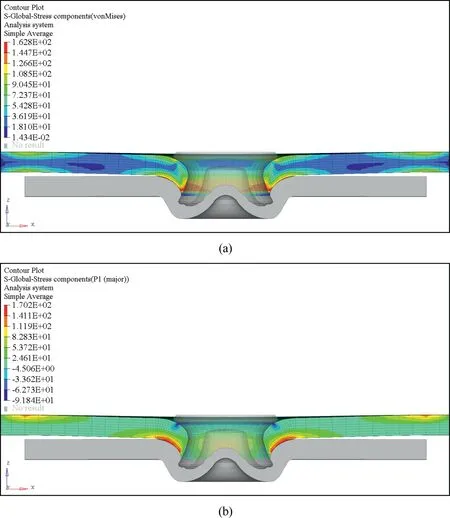
Fig. 14. (a) Von-Mises and (b) maximum principal stress distributions of SPR joints for which P=373N at θ=90°.
Here, K0and K90are the equivalent stress intensity factor at the loading angles of 0° and 90°, respectively. Fig. 15(c)shows the result of the evaluation of the fatigue lifetimes of the specimens at three loading angles when using the equivalent stress intensity factor. The equivalent stress intensity factor is not useful for evaluating the fatigue lifetimes of the SPR specimens at these three loading angles.Thus,after evaluating the fatigue lifetimes at various loading angles by applying these three parameters, the maximum principal stress was found to be able to evaluate the fatigue lifetime most appropriately. The relationship between the maximum principal stress (σ1) and the number of cycles (Nf) was σ1=1101.5.
For the fatigue lifetime evaluation at various loading angles of Al-5052 SPR joints, the equivalent stress intensity factor is reported to be the most suitable evaluation parameter [23,25]. In the current study, which evaluated the fatigue lifetimes of Mg/SPCC SPR joints, the maximum principal stress was found to be most appropriate. However, the reason why, when predicting fatigue lifetimes, the equivalent stress intensity factor is the best parameter for Al-5052 SPR joints and the maximum principal stress is the best parameter for Mg/SPCC SPR joints are not known at present. This requires more in-depth investigations.
When a load is applied to a SPR joint, the stresses becomes more concentrated on the lower sheet. Thus, a material of high strength is typically utilized on the lower sheet when riveting dissimilar materials. SPR joints are a type of mechanical joint. Therefore, when a load is applied to this type of joint, fretting wear occurs at the joint between the two materials due to a micro-displacement mismatch. Crack initiation occurs initially in the material with lower strength or hardness due to fretting wear. In particular, the fatigue strength of a SPR joint in the high cycle fatigue regime depends on the degree of crack initiation resistance. Therefore,the fatigue strength in the high cycle fatigue regime of a SPR joint with dissimilar materials depends on the fatigue strength of the sheet with lower strength. If magnesium and steel are to be joined, the upper sheet must be magnesium with lower strength. In this case, it is judged that the fatigue strength of the upper sheet of this joint governs the fatigue strength of the joint.
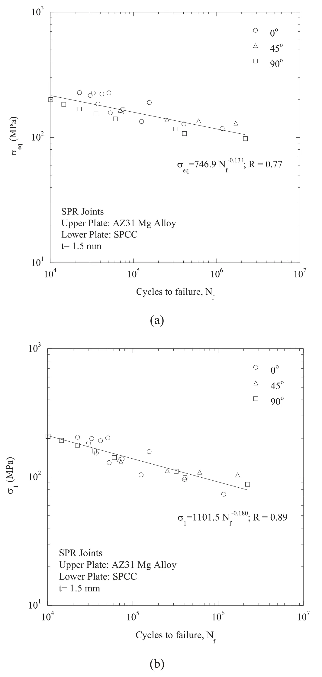
Fig. 15. Fatigue lifetime as a function of the (a) von-Mises stress, (b) maximum principal stress, and (c) equivalent stress intensity factor.
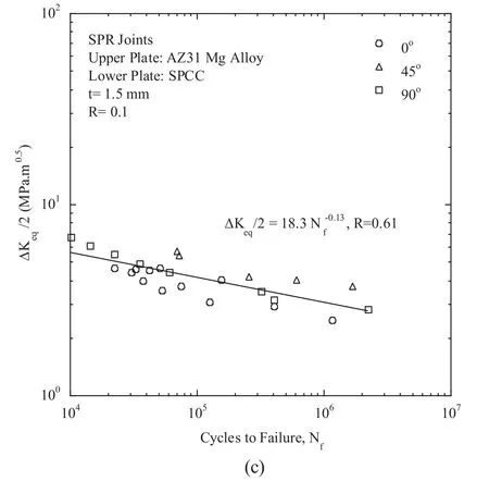
Fig. 15. Continued
4. Conclusions
In this study, monotonic and fatigue strengths of crossshaped SPR joint specimens with AZ31 magnesium alloy as an upper sheet and a cold-rolled steel sheet as a lower sheet were evaluated at loading angles of 0°, 45°, and 90°. The results are as follows.
1. For the specimens with the rolling direction of the upper sheet transverse to the loading direction, the monotonic strengths were 3764N, 2009N, and 1857N at loading angles of 0°, 45°, and 90°, respectively. In addition, the strengths of the specimens in which the rolling direction of the upper sheet was parallel or transverse to the loading direction were similar to each other.
2. Assuming a fatigue lifetime of 106cycles, the fatigue limits at loading angles of 0°, 45°, and 90° were 824N,257N and 168N, respectively. The fatigue ratio (= fatigue limit / static strength) at loading angles of 0°, 45°and 90° were 22%, 13% and 9%, respectively.
3. Fatigue initiation occurred at the triple point where the rivet shank,the upper sheet and the lower sheet all come into contact at all three loading angles.The cracks propagated through the thickness of the upper sheets, finally leading to a fracture when passing around the rivet.
4. The fatigue lifetimes at loading angle of 0°, 45°, and 90° are appropriately evaluated by the maximum principal stress rather than by the von-Mises stress or the equivalent stress intensity factor.
Declaration of Competing Interest
The authors declare that there are no conflicts of interest.
Acknowledgment
This study was supported by the Research Program funded by the SeoulTech (Seoul National University of Science &Technology).
杂志排行
Journal of Magnesium and Alloys的其它文章
- Latest research advances on magnesium and magnesium alloys worldwide
- Advances in coatings on biodegradable magnesium alloys
- Stability of twins in Mg alloys – A short review
- A review on thermal conductivity of magnesium and its alloys
- Effect of Ca addition on the microstructure and the mechanical properties of asymmetric double-sided friction stir welded AZ61 magnesium alloy
- Effect of pre-deformation on microstructure and mechanical properties of WE43 magnesium alloy II: Aging at 250 and 300 °C
