Corrosion fatigue of the extruded Mg–Zn–Y–Nd alloy in simulated body fluid
2020-04-29MengyoLiuJinfengWngShijieZhuYboZhngYufengSunLiguoWngShokngGunSchoolofMterilsSciencendEngineeringZhengzhouUniversityZhengzhou450001Chin
Mengyo Liu, Jinfeng Wng,b, Shijie Zhu,b,c,∗, Ybo Zhng, Yufeng Sun,b, Liguo Wng,b,c,Shokng Gun,b,c,∗School of Mterils Science nd Engineering, Zhengzhou University, Zhengzhou 450001, Chin
b Henan Key Laboratory of Advanced Magnesium Alloys, Zhengzhou 450002, China
c Key Laboratory of Advanced Materials Processing & Mold Ministry of Education, Zhengzhou 450002, China
Abstract Magnesium alloys were considered to be used as biodegradable implants due to their biocompatibility, biodegradability and nontoxicity.However, under the simultaneous action of corrosive environment and mechanical loading in human body, magnesium alloys are easy to be affected by corrosion fatigue and stress corrosion cracking. In this work, the fatigue behavior of the extruded Mg–Zn–Y–Nd alloy used for vascular stents was studied both in air and in simulated body fluid (SBF). It was revealed that the fatigue limit of as-extruded Mg–Zn–Y–Nd alloy in air is about 65MPa at 107 cycles, while there is no limit in SBF and shows a linear relationship between the fatigue life and stress amplitudes. The fatigue crack source in air was formed by the inclusions and defects. However, the stress corrosion and hydrogen embrittlement are the main reasons for the formation of the fatigue initial crack source in SBF.
Keywords: Biodegradable magnesium alloy; Corrosion fatigue; Simulated body fluid; Fatigue crack source.
1. Introduction
Magnesium and its alloys are becoming more and more promising lightweight metal that could be used in both engineering [1–3] and biomedical application [4–7] due to their good mechanical properties, biocompatibility, biodegradability and nontoxicity. Compared with the traditional vascular stent materials (e.g. stainless steel and titanium alloys),magnesium alloys have a prominent feature that it can be self-degraded in the human body during the service period.The mechanical properties of biodegradable magnesium alloys could be improved by adding alloying elements (such as Zn,Ca,Y,Nd,Sr and Sn etc.)[8–12]or reinforced particles(such as hydroxyapatite, calcium polyphosphate, and β-tricalcium phosphate) [7,8] However, the decrease of mechanical properties and fatigue failure of Mg alloys are prone to occur after being implanted into the human body due to the pulsating load of cyclic systolic, diastolic blood pressure and the long-term influence of body temperature at 37°C. As a result,the deformation, collapse, displacement and even fracture of the Mg alloy stents could take place. In addition, the stents simultaneously play a role of supporting the vessel and suffer from Cl−ion corrosion in the blood at the same time. Under the combined effects of stress and corrosion environment, the corrosion degradation behavior of stents is complicated, and the mechanical properties of stents are seriously decreased.Thus, the study on stress corrosion cracking (SCC) and corrosion fatigue (CF) has gradually become one of the research hotspot [13].
It is an indisputable fact that fatigue performance of Mg alloys will deteriorate seriously in corrosive environment.Bhuiyan et al. [14] investigated the fatigue strength of extruded AZ61 alloy in the corrosion environment of high humidity 5wt.%NaCl solution and 5wt.%CaCl2solution,respectively. It is revealed that the fatigue strengths in all three environments were drastically reduced. Jafari et al. [15] also found the similar results for the AZ91D alloy immersed in m-SBF. For biomedical magnesium alloys, it is essential to investigate the corrosion fatigue in pseudo-physiological environment to evaluate their performance.In recent years,several works focused on the corrosion fatigue properties of Mg in pseudo-physiological environment has been published. The studies on the corrosion fatigue of magnesium alloys showed that the corrosion fatigue crack originated mainly from the corrosion pits [16]. Gu et al. [17] found that the initial cracks of both AZ91D and WE43 alloy in SBF solution originated from corrosion pits; Jafari et al. [18] reported that the initial crack source of ZX10 magnesium alloy in m-SBF solution was corrosion pits.The anodic dissolution of the second phase accelerated the short cracks propagation and promoted the formation of initial fatigue source.Bian et al.[19]showed that the initial fatigue cracks of HP-Mg, Mg1Ca and Mg2Zn0.2Ca in SBF are also corrosion pits, and the formation of corrosion pit is considered to be caused by the defect of sample surface or the corrosive medium. But in the corrosion fatigue test of magnesium alloy tubes, the possibility of corrosion fatigue fracture caused by introducing of hydrogen into the sample was proposed by Dietzeld et al. [20]. Nevertheless, due to the wide variety of corrosive environments and tested alloys [21],the understanding of corrosion fatigue mechanisms of Mg and Mg alloys is still incomplete up to now [16]. It is thus worthy to be paid more attention to fatigue mechanisms of Mg and its alloys, especially in para-physiological environment [22].
Mg–Zn–RE alloys have been designed for biomedical application and have been proven to have good mechanical properties, deformation properties, corrosion resistance and biocompatibility[23].However,the corrosion fatigue behavior of Mg–Zn–RE is not clear,which is one of the most important properties for implant biodegradable materials. Mg–Zn–Y–Nd alloy has been developed for vascular stent medical implantable materials and is considered to have a good prospect of sustainable developments [24-30]. In this study,the extruded Mg–Zn–Y–Nd alloy was selected for fatigue and corrosion fatigue tests. The corrosion fatigue mechanism of the alloy in SBF solution was purposed by fatigue fracture analysis in order to provide fundamental information for further research. We believe this work is beneficial to the wide use of this type of Mg alloys for the biomedical application.
2. Experimental
2.1. Materials
The Mg–Zn–Y–Nd alloy was used in this work and the chemical composition of the alloy is listed in Table 1. The samples for fatigue and corrosion fatigue tests were machined from 20mm round bar. The shape and dimensions of samples are shown in Fig. 1a. After being machined, the specimens were ground with 100–1000 grit emery papers, polished 0.25μm diamond polishing agent and finally washedwith alcohol. Fig. 1b shows the appearance of the sample after polishing.

Table 1 Real chemical composition of Mg–Zn–Y–Nd alloy.
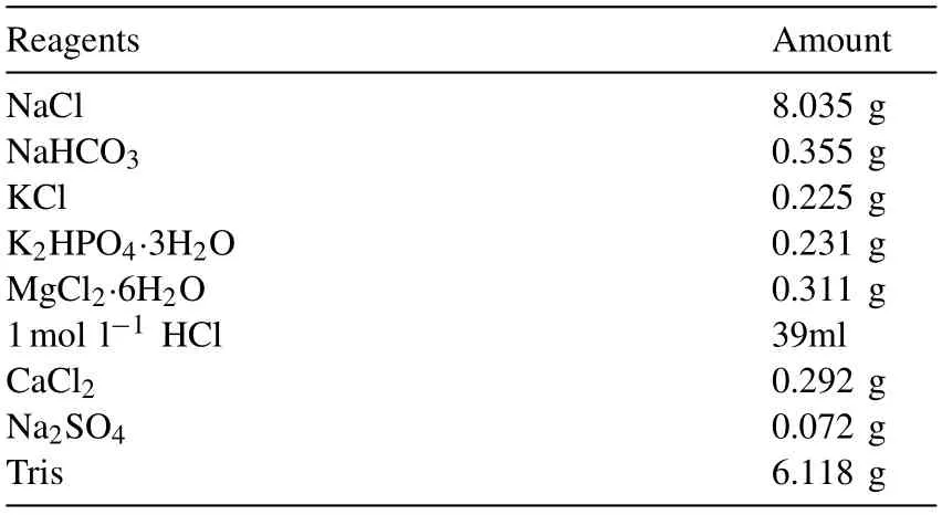
Table 2 Amount of reagents for preparing 1000ml of the SBF solution.
2.2. Mechanical properties
Mechanical properties tests were carried out by MTS machine (Bionix 370.2) at a cross-head rate of 0.5mm/min. The same specimens were used in fatigue testing.
2.3. Fatigue and corrosion fatigue test
Fatigue tests and corrosion fatigue tests were performed using a MTS machine under sinusoidal wave load. The stress ratio of fatigue and corrosion fatigue tests were set at R=−1 with a frequency of 5Hz. The fatigue and corrosion fatigue tests were terminated until failure of the specimens occurred or the test cycles were reached up to 107c.
For corrosion fatigue,the circular corrosion chamber needs to be constructed in order to simulate the body environment more closely. The schematic diagram of the device for corrosion fatigue tests is showed in Fig. 2. The gage of the sample is located in the corrosion chamber to prevent galvanic corrosion between the sample and the grips in solution. Silicone seal is used below the corrosion chamber to prevent leakage.The temperature of the SBF stored in a thermostat water bath was maintained at 37 ± 1°C. A peristaltic pump was used to provide power and control the flow rate. The peristaltic pumps only took act on the silicone tubes without polluting liquids. In this condition, the solution flow rate was set to 30ml/min. Table 2 lists the composition of SBF solution with a pH = 7.42 ± 0.02.
2.4. Fractography
Fatigue fracture reveals all the information of fatigue process. To observe the corrosion fatigue fracture surface clearly,the samples were cleaned by chromic acid solution (200g/L CrO3+10g/L AgNO3) to remove the corrosion products,cleaned by deionized water,and then dried.Fatigue and corrosion fatigue fracture surfaces were observed by using scanning electron microscopy (SEM, FEI Quanta 200).

Fig. 1. specimen shape and dimensions (a); specimen after processed and polished (b).
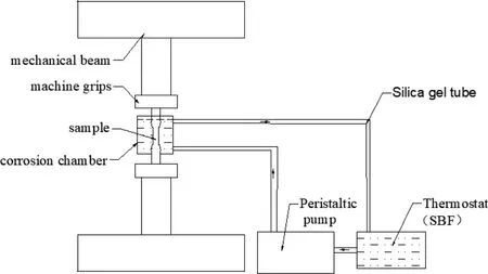
Fig. 2. The device diagram for corrosion fatigue test.
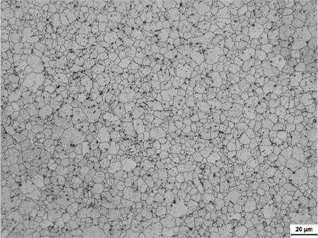
Fig. 3. Microstructures of the extruded Mg–Zn–Y–Nd alloy.
3. Results and discussion
3.1. Microstructure and mechanical properties
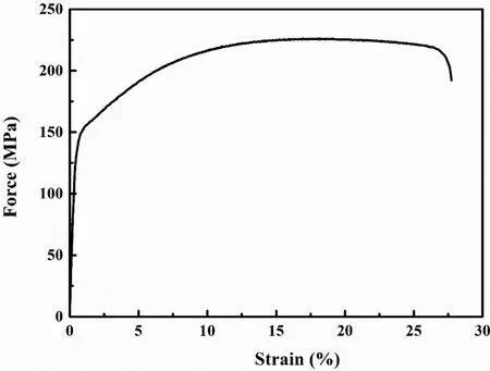
Fig. 4. The tensile stress–strain curve of the extruded Mg–Zn–Y–Nd alloy.

Table 3 Mechanical properties of as-extrude Mg–Zn–Y–Nd magnesium alloy.
Fig. 3 shows the microstructure of extruded Mg–Zn–Y–Nd alloy. The grain size was not homogeneous with an average grain size of 6.88±3.24μm. The grain size has an effect on the fatigue crack growth threshold. The crack growth threshold is larger for the larger grain size. However, the effect of grain size on yield strength is opposite. Fig. 4 shows the tensile stress-strain curve of the extruded Mg–Zn–Y–Nd alloy and the mechanical properties are listed in Table 3. The yield strength and ultimate tensile strength of the Mg–Zn–Y–Nd alloy were 159 ± 8MPa and 229 ± 6MPa, respectively. The alloy had a large elongation of about 26.7±0.8%. In the air fatigue tests, the propagation time of fatigue crack accounts for about 90% of the total time of the fatigue test. Based on the relationship between fatigue strength and mechanical properties, the fatigue life of the materials could be improved by increasing their tensile strength. However, when the fatigue tests were performed in solution, the propagation time of fatigue crack only took up a small part of the whole fatigue process. Once the fatigue crack source is formed,the crack could rapidly expand until it was broken under the action of liquid and stress. At that time, the improvement of the mechanical properties is negligible for prolonging the fatigue life of the specimen.

Fig. 5. The stress-life (S–N) curves for extruded Mg–Zn–Y–Nd alloy of fatigue and corrosion fatigue in SBF (arrows indicate that the specimens did not fail at 107cycles.).

Table 4 Experimental results of fatigue and corrosion fatigue.
3.2. The S–N curves of fatigue and corrosion fatigue
Fig. 5 shows the fatigue and corrosion fatigue stress-life(S–N) curves of extruded Mg–Zn–Y–Nd alloy in air and SBF solution. Table 4 summarized the fatigue lives under different stresses. It could be found that the fatigue limit in air was 107cycles at about 65MPa. While, no obvious limit was detected when the specimen was tested in SBF and a linear relationship between the fatigue life and stress amplitudes was found. The presence of corrosive environment caused obvious difference in fatigue performance. As we know, fatigue fracture originates from stress concentration caused by internal defects [31,32]. However, the stress concentration in corrosion fatigue is caused by the defects on the sample surface due to corrosion, such as cracks and corrosion pits [33,34].
When the specimen reaches the fatigue limit, the stress concentration caused by the internal defects is usually small and cannot make the fatigue crack to start. But under such conditions, the stress concentration caused by corrosion increases with the test time and could cause the initial fatigue crack source to be formed. Therefore, there is no infinite life for the corrosion fatigue tests [33].
The fatigue tests in air showed very different results when specimen tested under a stress of 70MPa. One specimen reached the fatigue limit without failure while the others failed very quickly. This is because the fatigue test is susceptible to the processing and the internal defects of the specimens. The fatigue properties of specimens will decrease when the large defects exist.Corrosion fatigue is a mixed process of mechanical and corrosion [35]. It shows that the corrosion fatigue properties of the specimens depend mainly on the mechanical properties of the materials at high stress levels. But under the action of a lower stress, the corrosion properties of the materials will play a greater role in the corrosion fatigue. It can be seen from Fig. 5 that at 80MPa stress amplitude the fatigue life of the specimens was close to each other whether in air or in SBF,which indicated that the corrosion of the SBF on the specimen has few effect on the fatigue properties of the material under higher stress amplitude. With the decrease of stress amplitude, the influence of the liquid corrosion on fatigue becomes obvious.
3.3. Fatigue and corrosion fatigue fracture
Fig. 6 shows the fractography and fatigue crack sources of extruded Mg–Zn–Y–Nd alloy samples at different stresses in air.All of the fractographs exhibited three areas which are the crack initiation zone, crack propagation zone and finally the overload zone [19]. It shows that different initiators of fatigue source in air. Many small holes were formed by hard phases in the fatigue source area at a stress of 90MPa(Fig.6e),while the formation of fatigue source is due to slag and boundary slip at the stress of 80MPa (Fig. 6f and g). The sample will not break when the fatigue limit reached 107cycles at a stress of 70MPa. However, Fig. 6d and h shows different results.The fatigue fracture occurred earlier and even its fatigue life is lower than that of the specimen at a stress of 80MPa (this fatigue life of the specimen is 5.0×10⁴cycles). The larger internal defects directly reduced the formation time of fatigue source, and thus resulting in a serious reduction in the fatigue life of the sample.

Fig. 6. Fractographs and fatigue sources of the as-extrude Mg–Zn–Nd–Y alloy samples at different stress in air: (a) (e) Fractograph and fatigue source failure at 90MPa stress with 2.1×10⁴ cycles; (b) (f) Fractograph and fatigue source failure at 80MPa stress with 4.8×10⁴ cycles; (c) (g) Fractograph and fatigue source failure at 80MPa stress with 6.1×10⁴ cycles; (d) (h) Fractograph and fatigue source failure at 70MPa stress with 4.9×10⁴cycles.
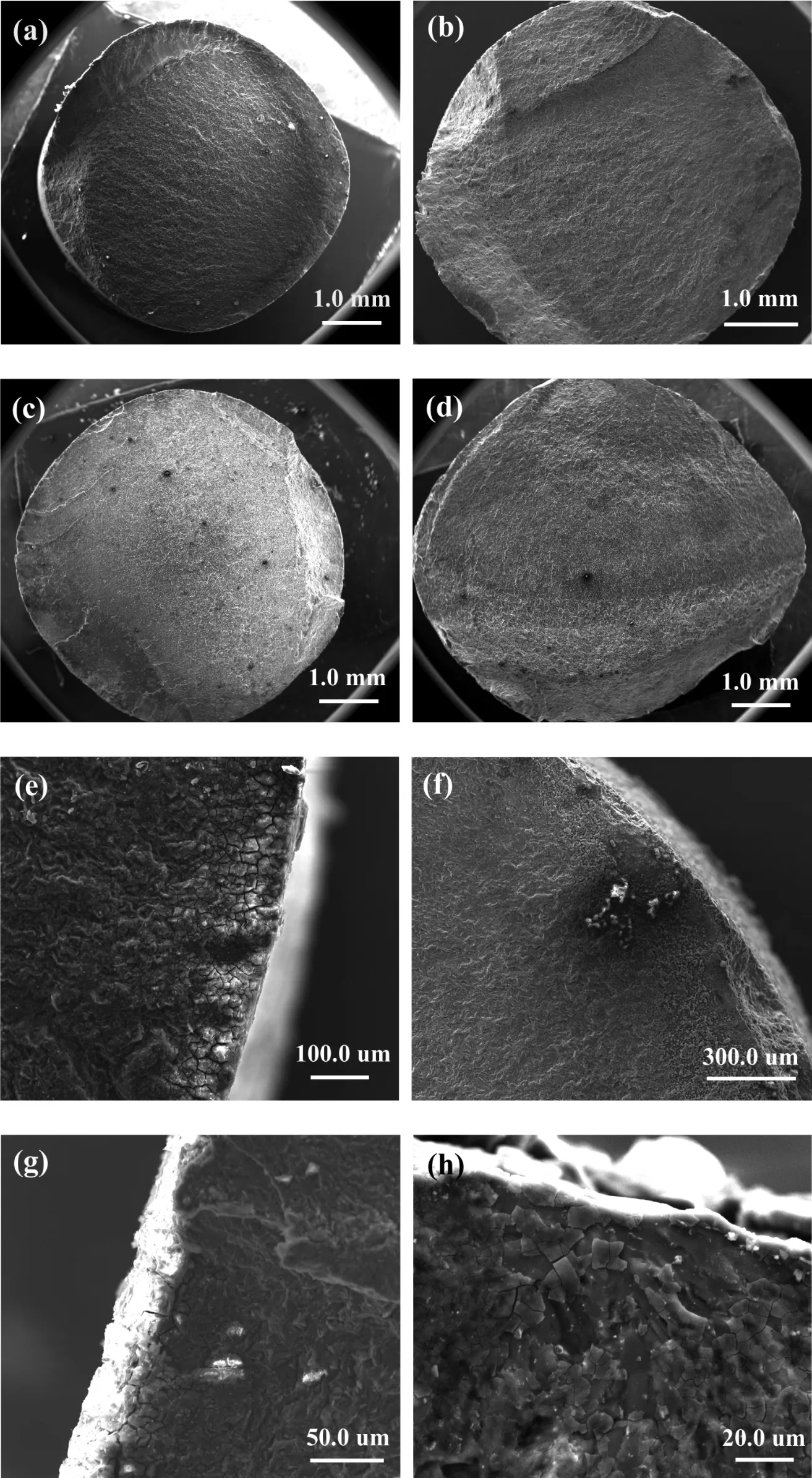
Fig. 7. Fractographs and corrosion fatigue sources of the as-extrude Mg–Zn–Nd–Y alloy samples at different stress in SBF: (a) (e) Fractograph and corrosion fatigue source failure at 80MPa stress with 6.1×10⁴cycles; (b) (f) Fractograph and corrosion fatigue source failure at 70MPa stress with1.8×105 cycles; (c)(g) Fractograph and corrosion fatigue source failure at 60MPa stress with 0.8×10⁶ cycles; (d) (h) Fractograph and corrosion fatigue source failure at 50MPa stress with 3.5×10⁶ cycles. (removing corrosion products (a)(c)(e)(g); without removing corrosion products (b)(d)(f)(h)).
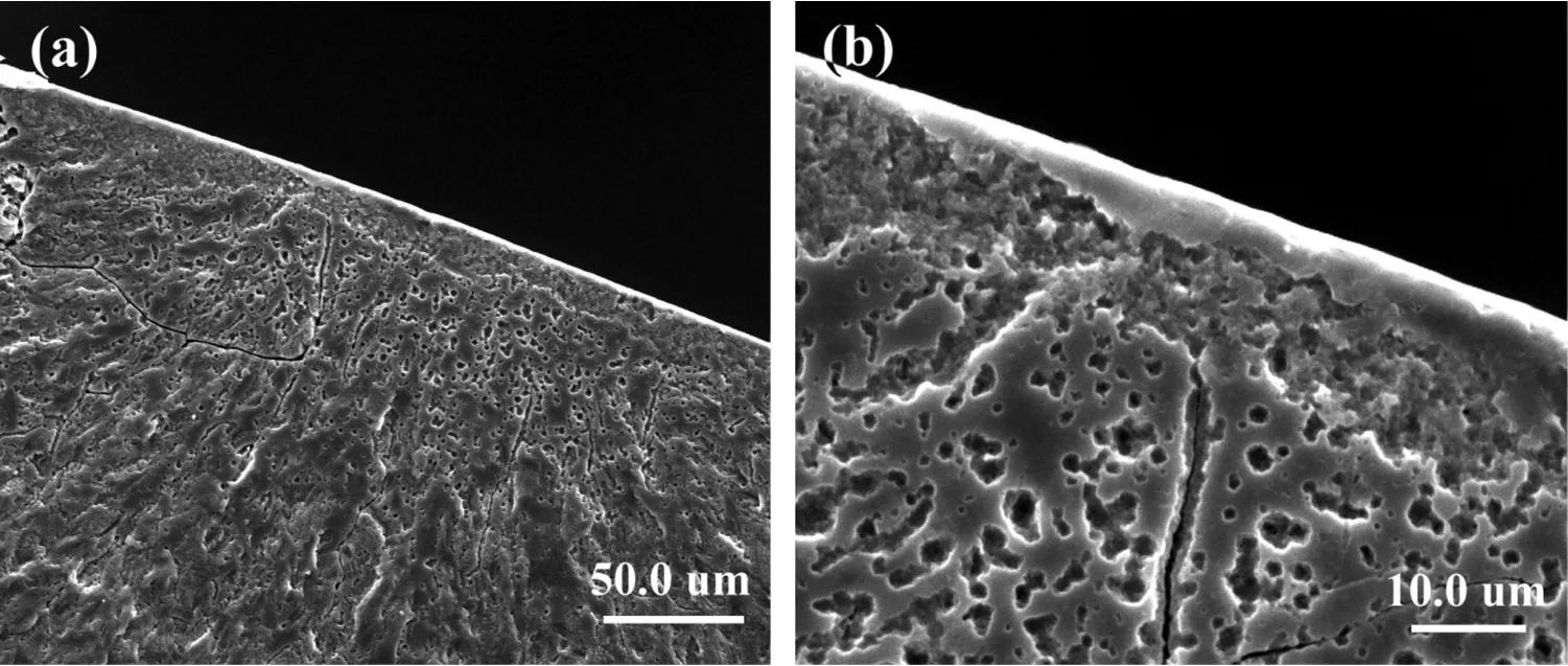
Fig. 8. The corrosion fatigue crack source of the Mg–Zn–Y–Nd alloy in SBF solution: (a) specimen was tested in SBF under the 70MPa stress with 2.0×10⁵ cycles (b) specimen was tested in SBF under the 60MPa stress with 1.0×10⁵ cycles.
Fig.7 shows the fractographs and corrosion fatigue sources of the as-extrude Mg–Zn–Y–Nd alloy samples under different stresses in SBF. The fractured specimen was removed from the SBF immediately when the specimen started to break except for those shown in Fig. 7c and g. The fatigue fracture shown in Fig.7c was immersed in SBF for several hours after the testing were stopped. The fatigue fracture with corrosion products as shown in Fig. 7a and c and the fracture without corrosion products as shown in Fig. 7b and d were observed by SEM. Although the specimens had been tested in a fluid environment for a long time, three distinct fatigue areas are still observed on the fracture surface of the specimens. It reveals that during the whole process of corrosion fatigue, the corrosion products formed in the extruded Mg–Zn–Y–Nd alloys do not make the liquid contact with the whole fatigue fracture.Only when the specimen fractured the SBF can enter and react with the fatigue fracture (Fig. 7c). Recent research[15/17/31] indicated that corrosion pits were inferred to have played a dominant role in the formation of fatigue source of magnesium alloys in corrosive liquid. The electrochemical inhomogeneity on the surface of specimens is caused by the second phase, impurities and fatigue damage, which provides conditions for the occurrence of pitting pits [18]. However, in this study, the corrosion fatigue source for as-extruded Mg–Zn–Y–Nd alloy in SBF solution shown in Fig. 7 was flat but appeared to be cracks. From the Fig. 7e and g, the obvious corrosion cracking with corrosion products was observed.Liquids corroded the fatigue source but no corrosion pits were found. Stress corrosion also occurs during fatigue corrosion[22]. The stress corrosion fracture of magnesium alloys will be corroded due to the anodic dissolution. When the corrosion products are not removed, the corrosion products with muddy cracks appear on the initial corrosion fracture zone.But the fracture surface is smooth after the removal of the corrosion products. The morphological characteristics of the corrosion fatigue crack source zone in Fig. 7 are consistent with those under stress corrosion.
In addition, it can be seen that fatigue fracture in air usually has only one fatigue source, but the specimens in SBF shows multiple fatigue sources (Fig. 7b and c), and the number of fatigue sources increases with the decrease of stress amplitude. Samples under a low stress amplitude have a longer fatigue life, which means that the corrosion time will be prolonged. It is known that fatigue source is the place where the fatigue crack originates. The fatigue crack needs to reach a certain critical size (in order to get the enough high micro local stress) to form the fatigue source. Micro local stress gradually increases with the progress of corrosion,the new fatigue crack nucleation formed resulting in multiple crack sources in SBF. And with the increase of corrosion time, other new stress concentration zone would form on the surface of the specimen and gradually become a new fatigue source. Therefore, it is very easy to form multiple corrosion fatigue crack sources in corrosion fatigue.
Fig. 8 shows the different corrosion fatigue crack sources.Tear edges and micropores were found at the crack source of corrosion fatigue. According to the corrosion fatigue adsorption theory, metals can adsorb active substances in the reaction process, which results in the reduction of metal surface energy, weakening of mechanical properties and the formation of corrosion fatigue cracks. It has been proved that hydrogen participates in the process of crack growth, thus accelerates the crack growth [13/15]. As it is known, hydrogen will be generated during the reaction of magnesium alloys in solution [5]. The generated hydrogen may enter the material and accumulate, resulting in the local stress concentration and cracks. This is also an important reason for which the corrosion fatigue crack source was formed. In other words,hydrogen embrittlement of magnesium alloys may lead to the formation of crack sources of corrosion fatigue.
3.4. The formation mechanism of corrosion fatigue crack source
In air, the fatigue property has a great relationship with the material. The fatigue crack source is formed by the defects of the material. However, in corrosive environment, the formation mechanism of corrosion fatigue is more complex due to the addition of liquid corrosion. In order to know more about the fatigue behavior, the specimen surface of as-extrude Mg–Zn–Y–Nd alloy after removing corrosion products in SBF and fatigue in air are presented in Fig. 9. Fig. 9a shows the surface of the specimen which has reached the fatigue limit under a stress of 70MPa in air and has been broken at the displacement rate of 0.5mm/min. As shown in Fig. 9a, persistent slip bands (PSBs) appeared perpendicular to the stress direction on the specimen surface [36] under the cyclic axial tension and compression stress in air. The propagation of the PSBs gradually initiates cracks, which eventually leads to the failure of the specimen under the alternating stress. Therefore, no PSBs is observed on the outer surface of specimens without fatigue fracture, as shown in Fig. 9b. At the same time as shown in Fig. 9c, steps and micro cracks perpendicular to the stress direction were formed on the surface of the specimen after cyclic loading in corrosion environment. The PSBs also appears in corrosion environment. The potential difference between the slip deformation area and the undeformed area causes the galvanic corrosion to occur in SBF environment. The deformation area is acting as an anode and the undeformed area a cathode [37]. Steps and micro cracks are formed under the action of anodic dissolution. Certainly,corrosion products and exposed new areas will also form corrosion electrochemistry to promote anodic dissolution, accelerate corrosion rate and increase stress concentration under tensile stress.
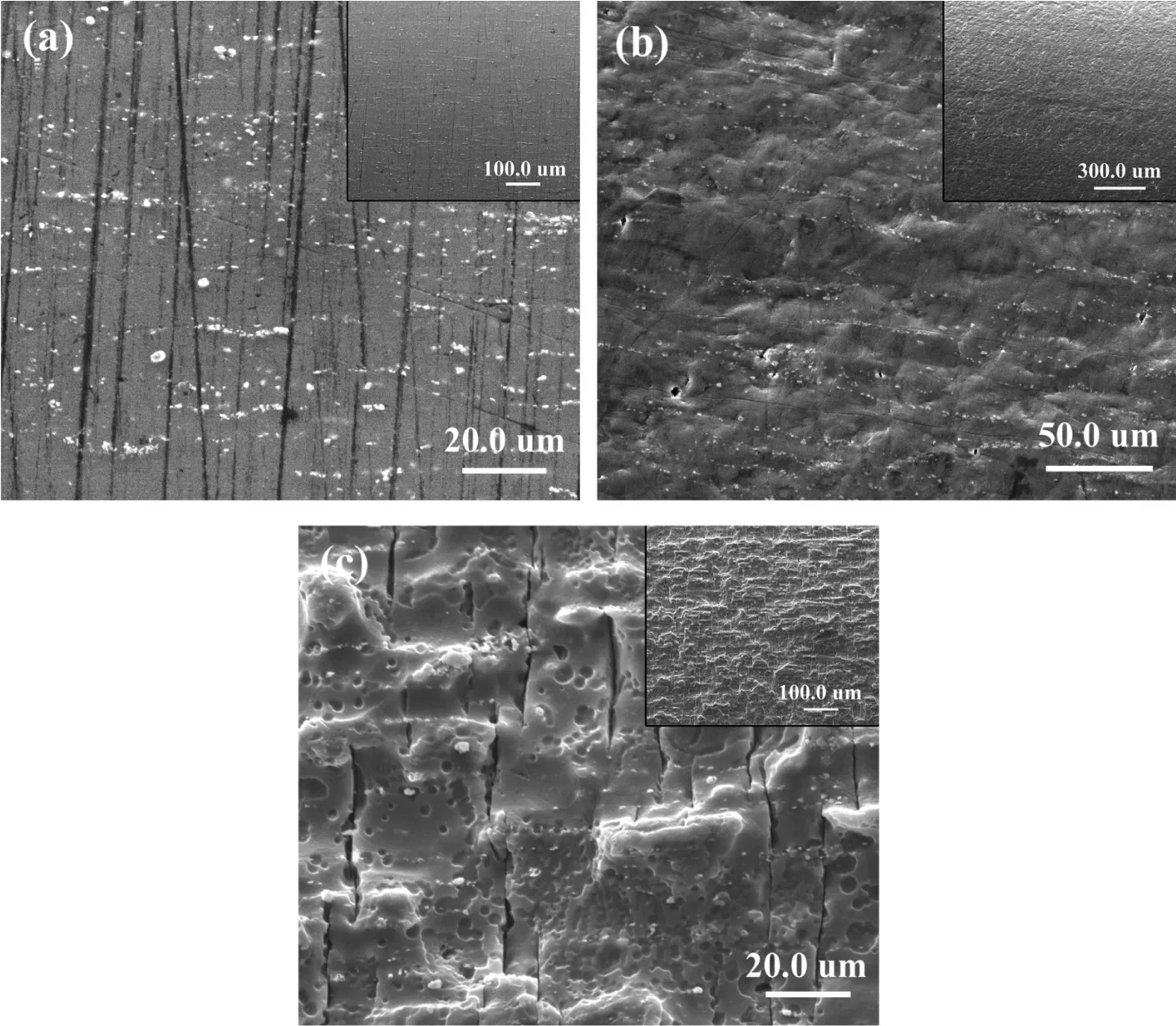
Fig. 9. The specimen surface of the as-extrude Mg–Zn–Y–Nd alloy after removing corrosion products in SBF and fatigue in air: (a) specimen was tested in air under the 80MPa stress with 5.0×10⁴ cycles; (b) specimen was tested in air under the 70MPa but not broken; (c) specimen was tested in SBF under the 70MPa stress with 1.8×10⁵ cycles.

Fig. 10. The mechanism of corrosion fatigue crack initiation for as-extrude Mg–Zn–Y–Nd alloy in SBF.
According to the above descriptions, the mechanism that the corrosion fatigue crack caused by stress corrosion for as-extruded Mg–Zn–Y–Nd alloy in SBF can be proposed to explain the formation of fatigue initial crack source, except for the formation of corrosion fatigue cracks caused by hydrogen,. At the beginning of corrosion fatigue test as shown in Fig.10,a corrosion product layer is rapidly formed on the surface of the sample as the sample contacts with the simulated body fluid and uniformly distributed on the whole sample surface (Fig. 10a) to protect specimen from being corroded.However,the slip band was formed on the surface of the sample with the increase of cycle number and gradually widened under the tension and compression stress. As a result, the steps and new planes were formed and caused the stress concentration to occur (Fig. 10b). Magnesium alloys are sensitive to stress corrosion(SCC)[38–42].When the cracks caused by stress corrosion reaches critical size at tension stress, the initial fatigue source would be formed(Fig.10c).In addition,the corrosion fatigue fracture remained original morphology in SBF environment (Fig. 7). This is because that the corrosion products formed by as-extruded Mg–Zn–Y–Nd alloy in SBF are not easy to fall off under certain stress amplitude (circulating fluid cannot generate shear force on the surface of sample). The corrosion products produced at the new plane are still located on the surface of the specimen to protect the fatigue fracture from liquid corrosion (Fig. 10d) until specimen fails.
4. Conclusion
(1) From fatigue S–N curves, the fatigue limit of the asextrude Mg–Zn–Y–Nd alloy in air was 65MPa at 107cycles. However, no obvious fatigue life limit in SBF was found and a linear relationship between the fatigue life and stress amplitudes can be obtained.
(2) The defects caused by the stress concentration are the initiation sites for fatigue source in air, while cracks caused by stress corrosion and hydrogen embrittlement play an important role in the corrosion fatigue of asextruded Mg–Zn–Y–Nd alloy in SBF.
(3) The as-extruded Mg–Zn–Y–Nd alloy specimens subjected to fatigue in air usually have one fatigue crack source. In SBF, the samples under low stress amplitude have longer fatigue life. Meanwhile, with the progression of corrosion, the new fatigue crack nucleated and resulted in the formation of multiple crack sources.
Declaration of Competing Interest
The authors declare that they have no known competing financial interests or personal relationships that could have appeared to influence the work reported in this paper.
Acknowledgments
The authors are grateful for the financial support of Key Projects of the Joint Fund of the National Natural Science Foundation of China (No. U1804251),the National Key Research and Development Program of China (No. 2018YFC1106703, 2017YFB0702504 and 2016YFC1102403).
杂志排行
Journal of Magnesium and Alloys的其它文章
- Latest research advances on magnesium and magnesium alloys worldwide
- Advances in coatings on biodegradable magnesium alloys
- Stability of twins in Mg alloys – A short review
- A review on thermal conductivity of magnesium and its alloys
- Effect of Ca addition on the microstructure and the mechanical properties of asymmetric double-sided friction stir welded AZ61 magnesium alloy
- Effect of pre-deformation on microstructure and mechanical properties of WE43 magnesium alloy II: Aging at 250 and 300 °C
