Mechanism of accelerated dissolution of mineral crystals by cavitation erosion
2020-04-26·
·
Abstract Cavitation, a phenomenon produced by a moving fluid, is ubiquitous in the water environment of the Earth’s surface and its related mechanical action in the process of cavitation leads to the widespread erosion of rock in nature. Although the mechanical action of flowing water body that accelerates the rock mass loss and fragmentation of rock (abrasion, erosion, and etching) and other phenomena have been much studied, its acceleration of mineral crystal dissolution is rarely reported. The physical mechanism of effect is not yet clear. The cavitation bubble produced in the cavitation process is at the micron level, and its related mechanical action leading to the accumulation of rock mineral dissolution is manifested in time and space in the process of the chemical element’s migration between water and rock minerals. Cavitation erosion may be one of the important driving forces for the migration of geochemical elements within the lithosphere and hydrosphere. In this paper, based on the crystal dissolution stepwave dynamic theory and the theoretical derivation and calculation of Gibbs free energy change of the mineral crystals plastic deformation which caused by the mechanical action of cavitation erosion, we give the possible mechanism of accelerating the transient dissolution of mineral crystals by cavitation erosion—the cavitation bubbles on the surface of the near crystal release the high speed micro-jet and shock wave perpendicular to the surface during the collapsing, in which the water hammer pressure produced by micro-jet at the solid–liquid interface causes instantaneous plastic deformation on the crystal surface under the condition that it is larger than the yield stress of the crystal. Under the influence of the thermal effect of the plastic deformation process and the change of Gibbs free energy (the dislocation elastic strain energy of plastic deformation on the crystal surface may be included), the local instantaneous dissolution rate of the mineral surface is accelerated. The continuous cavitation erosion eventually causes fracture and breaking of the mineral crystal, meanwhile, the Gibbs–Thomson effect may enhance the dissolution of mineral crystals more prominently. At the same time, the correctness of the mechanism is verified qualitatively by the acoustic cavitation experiment with the same erosion mechanism.
Keywords Cavitation erosion · Mineral dissolution ·Plastic deformation · Stepwave · Gibbs free energy
1 Introduction
Cavitation refers to the dynamic phase change phenomenon that occurs in a liquid when the hydrostatic pressure of a liquid is lower than the vapor pressure of a liquid (Kenneth 1989; Sreedhar et al. 2017), which is characterized by the generation of tiny bubbles (microns)in the liquid. When the hydrostatic pressure of the liquid increases and recovers, the sharp compression (near adiabatic compression)of the bubbles on the near solid surface is until the collapse.While the asymmetric compression of the cavitation bubbles near the solid surface produces the high-speed micro-jet and shock wave perpendicular to the solid surface in the collapsing moment, which leads to the plastic deformation of the solid surface in a very short time.The accumulation of long-term erosion effects can further lead to solid breakage and material mass loss (Karimi and Martin 1986).
The interaction between water bodies and rocks is more common because the hydrosphere is closely related to the lithosphere on the Earth’s surface. On the macroscopic scale, the mechanical action of the Earth’s surface water body movement will lead to the change of topography and geomorphology. As a universal natural phenomenon in water movement, cavitation erosion also has an important influence on topography and geomorphology in the large space and time scale.
In the river, a series of processes, including cavitation erosion, abrasion, dissolution, and so on, can cause severe erosion of the bedrock in the riverbed(Kelin et al.2000).It has been reported that the erosion volume of granite riverbeds on the surface can be as high as 38,400 m3within 5 years.High-speed glacial melting snow flows through the rock surface due to its cavitation can also cause severe erosion to the rock (Clancy et al. 2001) When the wave flow is formed by the tsunami at a speed higher than 10 m per second, its hydrodynamic potential energy in the rock promontory can cause cavitation or small vortex and then produce a carved and etched surface (Viacheslav et al.2010).The cavitation is generated in 2 m deep waters and a high-speed wave of 10 m per second (Bryant 2008). For example, the impact marks with cavitation characteristics caused by a huge tsunami were widely distributed on the coast of New South Wales in eastern Australia. In the interior of the cavern, even if there is no violent water movement, but droplets dripping down from the top of the cavern produces a strong mechanical force at the moment of contact with the rock at the bottom by the action of gravity. Long-term mechanical accumulation of the droplets impinging can lead to puddles or water caves on the solid surface (even water drips penetrate the rock). The cavitation erosion effect is also generated in the process of contact between the droplet and the solid surface (Brian and Douglas 1995; Field et al. 2012). One of the causes of soil erosion and water droplets piercing stone is the accumulation of cavitation erosion over time.Erosion caused by the accumulation of cavitation will eventually result in deep pits or needle pits on solid surfaces (Buravova and Gordopolov 2011).
Although the mass loss and fragmentation of rock(such as abrasion, erosion, etching) caused by the mechanical action of the interaction between flowing water body and the rock are already concerned by most geoscience researchers, the mechanism study of flowing water mechanical action that enhances chemical dissolution of the surrounding rock is lacking. The mechanical action in the deep stratum has a prominent effect on the dissolution of rock and mineral (because of the dissolution effect caused by the great static pressure of the overlying rock layer, it is so-called the pressure solution effect). The dissolution caused by mechanical action in the Earth surface environment is not easy to detect and easy to be ignored by researchers due to the many influencing factors of rock or mineral dissolution, such as organic, inorganic acid and alkali, salt ions, complex ligands, organisms, microorganisms, and light and thermal radiation. However, the cavitation phenomenon is generated by the ubiquitous motion of the water body, the cavitation bubble produced in its cavitation process belongs to the micron level and its related mechanical action leads to the accumulation of rock mineral dissolution in time and space, which has a significant effect on the migration of chemical elements between the water body and rock minerals. It may be one of the important drivers of the migration of the Earth’s chemical elements between the lithosphere and the hydrosphere.Therefore, from a more microscopic point of view, cavitation erosion can be another physical mechanism to interpret the dissolution of rock minerals caused by the interaction between water and rocks.
In virtue of the asymmetric collapse of the cavitation bubble in the near solid surface during cavitation erosion,the vertical impact of the micro-jet on the solid surface(water hammer pressure effect) (Preece 1979; Isselin et al.1998)and the effect of the shock wave on the solid surface will lead to etching pits and needle pits.These tiny surface depressions are the miniature plastic deformation on the crystal surface. In material science, the microscopic interpretation of plastic deformation of crystal materials is the generation and glide of dislocation in the crystals (regardless of twining deformation) (Sylvie et al. 2011).
The theoretical model of modern crystal dissolution dynamics has obtained considerable experimental data support, such as the stepwave theoretical model of Lasaga and Luttge (2001), Dove and other people’s nucleation dissolution theory model (Dove et al. 2005) which developed on the basis of crystallization BCF theory and some mineral dissolution processes were successfully predicted by them.
The general mechanism of the most minerals dissolution kinetics is as following:because the surface morphology of the crystal directly affects the boundary and transport between the crystal and the solution interface during the dissolution of the surface of the mineral crystal. The visualization processes that usually dissolve on the surface of the crystal include (1) the crystal atomic-scale step of surface layer horizontal movement (step retreat). (2) The removal of surface atoms from kinks (the kinks at the etching pits or crystal edges(convex)are the starting points for the removal of atoms,the etching pits are caused by the nucleation of the surface).The nucleation of the etching pit is produced at the surface of the crystal defect,in which the defects include the point defect (impurity ions), the line defect(linear dislocation)and the plane defect.The elastic strain of crystals caused by various crystal defects can be released on the surface, resulting in the nucleation of the etching pits. The crystal surface step originated from the surface etching pits and edges of the crystals can retreat in the form of stepwaves (Lasaga and Luttge 2001; Dove et al. 2005).
The horizontal motion of the step of the crystal surface layer and the removal of atoms at the nucleus of the etching pit can be in agreement with the Lasaga theoretical model of the step wave. From this, we speculate that the tiny pits(needle pits)caused by cavitation erosion on the surface of mineral crystals in flowing water have the same effect as those formed by their own defects,alternatively,the elastic strain of dislocation produced by the plastic deformation on the surface of the crystal can be released on the surface to cause the nucleation of the etching pits. Consequently,cavitation erosion accelerates the dissolution of insoluble mineral crystals.
In view of the previous research, it is proved that acoustic cavitation has the same erosion mechanism and effect as hydraulic cavitation of flowing water (Cai et al.2001;Kenneth et al.1997)(the expansion and compression process of water medium during the propagation of sound waves in a water body will cause a series of cavitation phenomena—negative pressure bubble formation and collapse).The purpose of this paper is to calculate and deduce the thermodynamic and kinetic physical mechanism of cavitation erosion to accelerate the dissolution of mineral crystals, meanwhile, we also verify the correctness of the physical mechanism by using acoustic cavitation erosion to treat insoluble crystalline minerals experiment.
2 Basic theory
2.1 Crystal dissolution kinetics
Based on the kinetics transition state theory and classical BCF theory of crystal surface growth,the theoretical model of crystal dissolution stepwaves has been proposed by Lasaga and Luttge, in which the crystal dissolution rate associated with the stepwaves on the crystal surface rate is:


Rate: crystal dissolution rate; ΔG: the dissolution process Gibbs free energy change; ΔGcrit: critical Gibbs free energy change; k: Boltzmann constant; T: temperature;tanh: hyperbolic tangent function; rpit: critical radius of surface stepwaves released from etching pit (the minimum value of stepwaves expansion rate is located at the distance from the starting etching pit wall);f ΔG,r( ):crystal surface step wave expansion rate function; σ: surface free energy;v: molecular volume; u(r): elastic Strain energy density at dislocation nucleation; A: mineral crystal dissolution rate constant, can be measured by the dissolution rate away from the equilibrium state; B: experimental determination of constants. One of the dislocation elastic strain energy density is:

μ:volume shear modulus;b:dislocation burgers vector;K:dislocation geometric distribution parameters, usually can be approximate to think of K ≈1; The dislocation elastic strain energy density given by Lasaga is derived from the linear dislocation of the crystal at a point where the dislocation line intersects with the crystal surface.
Here rhis defined as:
rh:that is,the Hooker radius,which is used to characterize nucleation (dislocation core) radius (Hoek et al. 1982).Similarly, the rhis derived from linear dislocation; ΔHm:the enthalpy of the melting of a molar mineral crystal.
The specific rpitvalue can be determined by the f ΔG,r( ), when the ΔG is constant, by formula (2.2):

Obviously, rpitas the solution of the above equation should be a positive real number. The general formula of dissolution rate derived from the transition state theory without considering the stepwave theoretical model is

R: gas constant; T:thermodynamic temperature; AP: ionic activity product of the environmental solution; Ksp: ion solubility product(or dissolution equilibrium constant Ke);s: solution ion saturation.
2.2 Thermodynamics of the crystal plastic deformation process
In the crystal dislocation theory, the plastic deformation Gibbs free energy can be denoted as (Galindo 2013):

Gpl-d: Gibbs free energy of crystal plastic deformation;Ggen: Gibbs free energy of dislocation generation; Gglid:Gibbs free energy of dislocation glide; Gannih: Gibbs free energy of dislocation annihilation. We are easy to know:

2.3 Cavitation bubble dynamics
According to Blake’s ultrasonic cavitation theory, the minimum ambient pressure for cavitation bubbles in the acoustic field is so-called the cavitation threshold (Luan 2015):

Pb: static pressure of liquid environment; P0: ambient atmospheric pressure;σ:liquid surface tension coefficient;R0:initial radius of bubbles.The liquid in the acoustic field can generate a cavitation phenomenon when ambient pressure (acoustic pressure) is greater than the cavitation threshold of cavitation bubbles (Ma 2013). Taking into account the liquid viscosity,surface tension,the influence of vapor pressure in cavitation bubbles and the radiant damping force produced by the process of the cavitation bubble shrinkage expansion oscillation (assuming that water is regarded as an incompressible fluid), we can obtain the kinetic equation of single cavitation bubble based on the classical Rayleigh–Plesset equation(Storey and Szeri 2000):

R: bubble radius at any time.t: time;bubble internal pressure, Pg: gas (air) partial pressure at any point in the bubble, Pv: saturated vapor pressure inside the bubble, γ:bubble gas adiabatic index;μ:motion viscosity coefficient;Pa:acoustic pressure amplitude;f:ultrasonic frequency;c:sound velocity in liquid;ρ:medium density.In the process of expansion and compression, the velocity of the cavitation bubble wall movement(expansion and shrinkage),the pressure and temperature of the bubble vary sharply. But the Storey (Storey and Szeri 2000) and other scholars showed that the water vapor content variability of cavitation bubble shrinkage is very little before and after the minimum volume.Ignoring the chemical reaction between each gas in the bubble, we can presume that the cavitation bubbles which consist only of air and water vapor, remain constant before and after the minimum volume. And the results of the Storey study showed that the molar fraction of water vapor is 14%. In the cavitation bubble shrinkage to the minimum volume stage, the internal pressure can be evenly distributed (Cai et al. 2001). So bubble internal pressure is:

Pb: bubble internal pressure; P0: initial cavitation bubble air pressure;Pbc:cavitation Bubble center air pressure;R0:the initial radius of the cavitation bubble; wherein mixed gas adiabatic index γ:

n1: the number of moles of air accounts for the proportion of a molar number of mixed gas; n2: the number of water vapor moles accounts for the proportion of a molar number of mixed gas; γ1: dry air adiabatic index; γ2: water vapor adiabatic index; the water vapor in the cavitation bubble can be considered as wet saturated steam,and its adiabatic index can be (Cai et al. 2001; Shen et al. 1995):

x is the wet saturated steam dryness, while in the real situation,the mass of the wet steam contained in the water vapor is much smaller than the mass of saturated waters,that is,x = 0,steam adiabatic index is γ2=1.035,thus not ideal dry air adiabatic index is γ1=1.436(Liu et al.2003)so γ = 1.167.Cai and other researchers(2001)according to the fixed mass of a single gas mass and momentum conservation equation, described the gas movement in the cavitation bubble and used the gas internal equation, heat transport equation and so on to deduce the cavitation bubble wall temperature Tbw. The cavitation bubble center gas can be considered as an ideal gas and has the highest temperature peak Tbc-maxin the compression process(Muthupandian 2011):

Pm: pressure in liquid (Pm=P0+Pa); Pv: pressure of cavitation bubbles at maximum size,usually assumed to be equal to liquid vapor pressure;Tbc:cavitation bubble center temperature; Tbw: cavitation bubble wall temperature; T∞:ambient liquid temperature; kl: liquid medium thermal conductivity; kg: gas thermal conductivity; δ: thermal boundary layer thickness over time(Kim et al. 2007),a:liquid thermal diffusion rate;t:the time of a period for the cavitation bubble existing. The cavitation bubble in the action of the external acoustic pressure field can do a series of volume expansion compression oscillation.In the oscillation compression process due to the huge kinetic energy of the surrounding liquid medium, the ambient liquid is in high-speed contraction.Although in the bubble compression process bubble internal pressure is greater than the environmental medium liquid pressure,inertial action makes the liquid medium and bubble system still maintain the compression trend with the huge compression rate (Fuster et al. 2009), eventually, the continuous compression of cavitation bubbles will be a collapse.Because the expansion and compression of cavitation bubbles occur in a very short period of time, the energy generated by instantaneous adiabatic compression can be released in the form of high-speed micro-jet and spherical shock waves at the moment of collapse.
2.4 Interaction between crystal surface and the collapse of near-wall cavitation bubbles
According to the Plesset and Chapman classical theory,Georges (2014) used digital regression to obtain micro-jet velocity ujet:
pcollpase: cavitation bubble outside the driving collapse pressure; ρ: liquid density; paSound field pressure; pb:bubble internal pressure; p0: atmospheric pressure. The pressure generated micro-jet impact on solid surfaces(water hammer pressure) (Plesset and Chapman 1971) is:
pwh:water hammer pressure;ρl:liquid medium density;cl:sound velocity in liquid; ρs: solid density; cs: sound velocity in solids. The plastic deformation of the solid surface is caused by the impact load on account of the water hammer action of the micro-jet when the cavitation bubble collapse. The mechanical deformation mechanism can be based on Plesset and Chapman’s theory. (Plesset and Chapman 1971; Matevzˇet al. 2006) The micro-jet impacting on the solid surface can bring about a critical velocity of plastic deformation νcrit:

pY: yield stress of solid material; ρ: density of liquid medium; parameter B = 301 MPa, n ≈7.15. Due to the conservation of energy, part of the water hammer pressure energy of the micro-jet will convert into plastic deformation energy:

νdef:apparent deformation velocity;νjet:micro-jet velocity;Since the water hammer pressure wave travels from the edge of the micro-jet to its center,tdefcan be interpreted as the time of traversing an impact stress signal (Lush 1983)(apparent deformation time):

rjet: micro-jet radius.
Because when the cavitation bubble collapses, the micro-jets impinge vertically on the solid surface. The central impact of the micro-jet leads to the stress concentration of the solid surface and on which the plastic flow maximum value dpitoccurs (thus, it is the depth of the etching pit formed by cavitation erosion):

For the process of contact heat conduction between cavitation bubbles and mineral crystal surfaces, it can be described by Newton’s law of cooling, Fourier’s law, and the laws of conservation of energy:
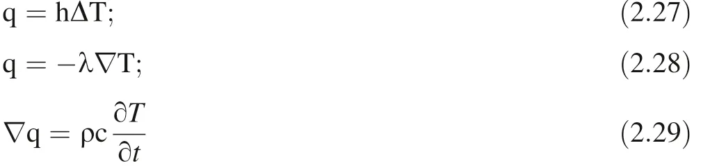
Q:heat flux density;h:surface heat transfer coefficient; λ:thermal conductivity; ∇T: temperature gradient; ∇:Hamiltonian operator; ρ: volume density; c: specific heat capacity; T: thermodynamic temperature; t: time.
The heat transfer coefficient of the surface between solid and fluid h is (Churchill et al. 1975; Sukhatme 2005):

λ: fluid thermal conductivity; RaL: Rayleigh number (dimensionless), which indicates that macroscopic buoyancy drives natural thermal convection; Pr: Prandtl number(dimensionless), which indicates the relationship between the boundary layer of fluid temperature and the flow boundary layer:

L: characteristic length; g: gravity acceleration; β: coefficient of thermal expansion; ν: dynamic viscosity (νμ thermodynamic viscosity, ρ volume density); Ts: interface temperature; T∞: temperature of far from the interface; a:thermal diffusion coefficient (a=In the light of the thickness of the bubble wall and the contact area between the bubble wall and the crystal surface are very small in the collapse stage of the near-wall cavitation bubble, it can be considered that there is only heat conduction without thermal convection in the bubble wall thickness δ range(δ is equal to the characteristic length of the thermal conduction between the cavitation bubble wall and the crystal surface,the thickness of the bubble wall is 10-6~10-7m,which exceeds the macroscopic convection size, so the convection effect is neglected).

In the moment of the cavitation bubble collapse,contact heat conduction finishes up. Here we only consider the near-surface heat distribution of minerals,regardless of the long-distance heat conduction inside the crystal, so the transient heat conduction relaxation time (lagging time)can be ignored.
For simplicity, we only do one-dimensional thermal conduction analysis of the surface contact between the cavitation bubble wall and the mineral crystal (subsequent calculations show that the thermal conduction of the bubble wall contact has little effect on the thermal dissolution of the mineral, and the two-dimensional heat conduction analysis is even less):

a: thermal diffusion coefficient.
2.5 Temperature distribution in the process of crystal plastic deformation
The temperature distribution in the process of crystal plastic deformation is obtained by the Energy conservation formula (Rusinek and Klepaczko 2009):

ρ: mass density; Cp: constant pressure heat capacity; λ:thermal conductivity; β: Taylor–Quinney coefficient,which expresses the part of the mechanical power that acts as a thermal source, it can be a simple ratio of the thermal to mechanical powers when there is only plastic deformation as an internal heat source. We assume it is the traditional value of 0.9 in material science (Tomasz and Alexis 2014); σ: applied stress;, temperature change with time;: plastic strain rateelastic strain ratethermal expansion coefficient; E: Young’s modulus; α:linear thermal expansion coefficient.
3 Experimental materials and instruments
We focus on the mineral crystal dissolution of cavitation erosion to resolve the problem of corresponding rock weathering in the natural environment and we should have selected quartz, feldspar, hornblende, mica for the experimental materials. However, these natural minerals involve numerous points defects or impurities in the high likelihood that defects lead to crystal physical properties change such as yield stress, Young’s modulus, coefficient of thermal conductivity, thermal capacity, coefficient of thermal expansion, Debye temperature. While as the widespread applied inorganic ceramic materials with simple stoichiometry, synthesized cubic zirconia, magnesium spinel, sapphire alpha-silica, these engineering ceramic materials can provide the more exact details of physical properties. A great quantity of published material science experimental data makes these details feasible to acquire.
So we selected gemstone grade synthetic mineral single crystal, including cubic zirconia (cubic-ZrO2), magnesium spinel (MgAl2O4), sapphire (α-Al2O3), all of which are pointed Princess square type (10 × 10) gem cutting (the Square bottom edge length 10 mm). The cubic zirconia was determined to contain approximately 10 mol%yttrium trioxide (Y2O3) stabilizer. The diameter of the cubic zirconia granule is 0.8 mm. The average diameter of industrial white corundum sand (containing a small amount of quartz sand α-SiO2impurities) is 4 to 6 mm.
Milli-Q®ultra-pure water; Kunshan brand Ultrasonic instrument,its single oscillator ultrasonic power 36 to 38.8 watts;single oscillator working acoustic flux area:diameter 6.6 to 7 cm circular region; operating frequency 40,000 Hz; Thermo®ICP-AES.
In light of the outstanding brittleness of polycrystalline ceramic materials such as zirconia, spinel, sapphire,corundum, it is easy to produce micro-cracks and fracture under the stress of cavitation erosion, which is called pseudoplastic deformation.But there is a permanent plastic deformation of the surface after cavitation exposure for the single ceramic crystal (Garcı´a et al. 2011).
4 Experimental processes
All the experimental mineral materials were repeatedly washed with ultrapure water and then ultrasonically treated in an ultrapure water environment for 30 min, subsequently, repeatedly washed with ultrapure water, and finally dried. The cleaned mineral materials were divided into groups, the same mineral materials were treated with three parallel samples for the ultrasound (cavitation erosion) as the experimental group, and one of the ultrapure water environments were placed without disturbance at the same temperature as the control group. The mineral materials in the experimental group were also placed in an ultrapure water environment with each ultrasound for 30 min.Interval of two ultrasound treatment with the same mineral material should be more than 4 h. After several times of cumulative ultrasound treatment, the ions concentration was determined by ICP-AES on the supernatant of the ultrapure water medium respectively, including Zr4+, Al3+, Si4+. In the same way, the ion concentration was determined after the different accumulating number of ultrasound treatment.
5 Theoretical calculation, mechanism derivation,experimental results comparison and discussion
5.1 Theoretical calculation and mechanism derivation
At the water temperature 25 °C, the working acoustic pressure of the experimental ultrasonic instrument is about 1.21×10⁵Pa, the corresponding Blake Cavitation threshold (Formula 2.14) has a minimum initial cavitation bubble radius of 2.2 μm. Due to the thermal effect of the ultrasonic process, the surface tension and viscosity of liquid varied with temperature. The temperature of the liquid medium (ultrapure water) increased from the initial temperature 20 to the 40 °C, after continuous 30-minute ultrasound treatment.
We also calculate that the initial radius of the minimum cavitation bubble is 2.1 μm when the temperature is 40 °C.Because the temperature variation range of the experimental process is around 20 °C, the cavitation effect has not changed much and the calculation process refers to other literature, thermodynamics and material physical properties data are obtained in the 25 °C, therefore, the physical parameters of the relevant process are calculated by using the ambient temperature of 25 °C. (Otherwise, it will be marked separately)Using formula(2.14–2.20),and pure water 25 °C physical parameters, experimental sound pressure:W: acoustic power 38 watts (oscillator Power conversion efficiency 98%); s: acoustic working flux area,; D: acoustic working flux area diameter; ρ: liquid (pure water) density; c: sound velocity in pure water; we can obtain the following(Table 1).
The calculation results from the table above can be obtained when the initial radius R0=9 μm, the minimum compression radius and the initial radius ratio reach the minimum=0.09), and the bubble internal pressure Pb=4368×105Pa when the minimum radius of compression is corresponding at this time, which is also the moment of cavitation bubble collapses. The maximum temperature in the bubble (the center temperature of the cavitation bubble)can be obtained by the cavitation bubble compression oscillation is 3487 K, while the temperature of the bubble wall is 3425 K. However, in the sameacoustic field and the liquid medium,the distribution of the number of cavitation bubbles with different sizes is not clear under the condition that it is higher than the cavitation threshold. But according to the previous studies, the size distribution of the corrosion pits on the surface of cavitation erosion materials conforms to the Weibull distribution,which means the number of pits decreases sharply with the increase of the diameter (Arvind et al. 2012). Generally,the pit diameter is positively correlated with the pit depth(Peng et al. 2018). When the water hammer pressure is high enough to cause plastic deformation on the crystal surface, the pit depth will increase as the water hammer pressure increasing, which also means that the number of corresponding pits will decrease sharply, as the water hammer pressure increases.
Table 1 Theoretical calculation of the ratioof the minimum compression radius (Rmin) to the initial radius (R0) of the cavitation bubbles of different initial radii and the bubble internal pressure Pb of the minimum compression radius

Table 1 Theoretical calculation of the ratioof the minimum compression radius (Rmin) to the initial radius (R0) of the cavitation bubbles of different initial radii and the bubble internal pressure Pb of the minimum compression radius
For formula (2.25), in order to determine the variable micro-jet radius rjet, we use the arithmetic average of cavitation bubble minimum compression radius Rmin(cavitation bubble radius at the time of collapsing)and 0.1 Rminto do an approximate replacement. Because the yield stress of the material is the threshold stress of the plastic flow of the material, we use the average flow stress approximation of the material instead of the yield stress(σflow≈σyield).Its average flow stress σflowcan be obtained by the following formula without considering the work hardening conditions (He et al. 2007):

H: Vickers hardness; E: Young’s modulus; σflow: average flow stress. Using formulas from (2.21)–(2.26), we can calculate the geometric deformation results of the mechanical interaction between the near-crystalsurface cavitation collapse and the crystal surface (Table 2).
By formula (2.29) to (2.32) the analytic solution of the partial differential equation of the specific one-dimensional heat conduction process is as following:

θ: residual temperature; T0: liquid medium ambient temperature (mineral crystal is equal to liquid ambient temperature without cavitation bubble); Tbw: cavitation bubble wall temperature; η,τ:is a dimensionless variable;x: one-dimensional heat conduction distance; h: surface heat transfer coefficient; a:thermal diffusion coefficient;t:contact heat conduction time; complementary error function: erfc( x)=Considering the asymmetric collapse of cavitation bubbles,we suppose that the distance of the micro-jet perpendicular to the surface of the mineral crystal passing through is equal to the diameter of the cavitation bubble before collapsing,which is the minimum diameter of the cavitation bubble compression. The heat conduction time between the cavitation bubble wall and the surface of mineral crystals is
From Table 3, it can be seen that the surface temperature of mineral crystals caused by the contact heat conduction of cavitation bubbles and mineral crystals is extremely limited, and the difference between the mineral surface and the ambient medium temperature of 298.15 K(25 °C) is not more than 15 K, so the influence of the dissolution of insoluble mineral crystals can be ignored.
On the basis of numerous previous experimental studies,such as molecular simulation microscopic elastoplastic deformation analysis and crystal indentation experiment(Tomohito and Yoji 2006; Nibur et al. 2007; Egberts and Bennewitz 2011), study on surface plastic deformation of mineral crystal cavitation erosion (Tsunenori et al. 1995;Kazuhisa 1989), study on surface morphology and crosssectional dislocation of mineral monocrystalline cavitation erosion (Hale et al. 2012), study on microstructure dislocation and residual stress produced by metal cavitation micro-jet (Jackson et al. 2006; Ju et al. 2011), those explicate that in the small area of the crystal surface, the plastic deformation under the action of vertical pressure will generate dislocations, which have a certain geometric relationship with the crystal surface, and lead to the glide of the dislocations along a certain direction. The glide of several unclosed dislocations intersecting within the crystal can form a closed dislocation loop. When the dislocation loops intersect on the surface of the crystal,the intersection site is usually an applied pressure concentration site.Exactly as the elastic strain energy equation of the mineral crystal own defects (impurity ions or linear dislocation,etc.) is about the nucleation of the surface etching pit, we need to obtain the elastic strain energy equation of the dislocation loop.Based on the Peach–Koehler equation,the general form of the dislocation loop elastic strain energy is deduced by Wei et al. (2006):


Table 2 Calculation results of the interaction between near the crystal surface cavitation bubble collapse and crystal surface

Table 3 Temperature of contact heat conduction between the cavitation bubble and mineral crystal surface at 1 nm on the inside of the mineral surface
R:radius of the dislocation loop;a:dislocation core width;μ: shear modulus; ν: Poisson’s ratio; b: Burger’s vector model.
In the crystal dissolution stepwave theory model of Lasaga and Luttge, the elastic strain energy at the intersection site of the linear dislocation and the surface of the crystal is considered as the nucleation driving force of the etching pit so that the stepwaves can be generated easily in the mineral surface layer.If the dislocation loop generated by the plastic deformation on the surface of the mineral crystal is equivalent to the linear dislocation in the crystal,the elastic strain energy at the intersection site of the dislocation loop and the surface of the mineral crystal may provide the same driving force about nucleation of the surface etching pit leading to stepwaves for mineral dissolution. It is assumed that the angle between the plane in which the dislocation loop is located and the surface of the crystal is φ, the dislocation loop, and the surface are intersecting at a point to form a nucleation of etching pit,as the starting point of the horizontal movement(step retreat)of the mineral crystal terraced surface layer. The distance of the etching pit center (nucleation) to the front of stepwaves surface expansion (step retreat) is r (the Cartesian coordinate system can be established in the plane on where the dislocation loop is located,the center of the dislocation loop is the origin of the coordinate system, and the schematic diagram is in Figs. 1, 2). The distance r is equal to the outside point of the dislocation loop on the glide plane(the plane on which the dislocation loop is located) to the center of the dislocation loop distance R0minus the dislocation loop radius R and then projected on the crystal surface (projection distance).

Obviously,the average elastic strain energy at a point on the dislocation loop:

Fig. 1 A schematic diagram of the dislocation ring intersecting on the surface of the crystal to produce an etching pit(nucleation)

Fig. 2 Diagram of the gliding plane (cross-section) where the dislocation ring is located

The elastic strain energy density on the crystal surface is equivalent to elastic strain energy at a point on a loop with a radius of R on the crystal surface.

The Hooker radius (nucleation radius) at a point on the dislocation loop is

Similarly, taking into account the rhradius of the Hooker nucleation can also characterize the dislocation core,the elastic strain energy density of the area where the dislocation loop intersects the surface of the crystal should be rewritten as:

When the elastic strain at the intersection of the dislocation loop caused by applied forces, the surface of the mineral crystal acts as the driving force of nucleation of the mineral crystal surface etching pit and the step wave generation and propagation, we can obtain the extreme value of the stepwaves rate by formula (2.2) and (2.3):

Thus at the minimum stepwaves rate,the corresponding rpitcan be determined by the following equation:

Of course, the solution rpitof Eq. (5.8) needs to meet positive real number conditions.
When the micro-jet produced in the process of cavitation erosion acts on the crystal surface with the water hammer effect,the solid–liquid interfacial water hammer pressure is greater than or equal to the yield stress (≈σflow) of the mineral crystal material, hence, many dislocation loops emerge near the inner surface of the crystal,the number of which can be determined by the formula of Taylor relationship (Dini et al. 2010) (where the water hammer pressure is equal to the applied stress):

σ: applied stress; σwh: water hammer pressure; M, α:geometric parameters, M·α ≈1; μ: shear modulus; ρ:applied stress dislocation density and the dislocation density is defined as the dislocation length within the unit volume.
In view of the similarity between the hammer pressure of the micro-jet and the plastic deformation caused by the indentation test, the plastic strain of the pits produced by cavitation erosion here can be calculated from the next approximation:
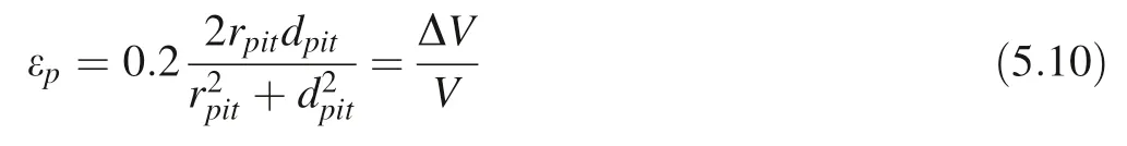
Here the surface of the pit is approximately regarded as a spherical indentation test head (spherical cap), and the surface shape of the pit is similar to that of the spherical crown (Davide et al. 2012) (schematic diagram shown in Fig. 3):

v: volume of a spherical concave pit (spherical cap);rjet-max: maximum micro-jet radius; Rb-min: the minimum radius of the cavitation bubble compression; ν: Poisson’s ratio;The total dislocation length of the plastic deformation region in each etching pit is l=ΔVρ;Here we assume that the face-centered cubic ZrO2(100) crystal plane is subjected to applied pressure. The equivalent crystal plane of the slip plane{110}with a total of four crystal planes.We only approximate the number of dislocation loops i (Assuming that the angle between the plane of the dislocation loop and the spherical surface of the deformation pit is 45°).

Fig. 3 A schematic diagram of a surface spherical concave pit similar to an indentation test produced by a micro-injection flow hammer pressure
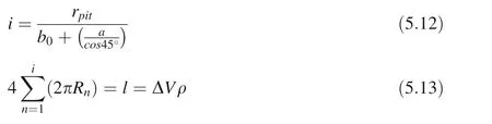
Here we also assume that α-SiO2{11} equivalent crystal plane is subjected to an applied pressure with the four slipping crystal orientationsand the angle between the plane of the dislocation loop and the spherical surface of the deformation pit is 30°or 0°. In the same way:

b0: average Zr–O bond lengths of cubic Zirconia (average Si–O bond length in α-SiO2crystal); a: dislocation core width (cutting radius) and it can be replaced by Hooker radius rh, which is interpreted as describing the radius of the nucleation region. We assume that the average size of Rn,is constant, and the strain depends on the number of dislocations and the glide distance. So the formula (5.14)can be rewritten:

The average yield stress(flow stress)of cubic-ZrO2and α-SiO2can be calculated by the previous table which is less than or equal to the maximum water hammer pressure(applied stress) of the cavitation bubble micro-jet at the solid–liquid interface.This means that the high yield stress MgAl2O4and α-Al2O3do not generate plastic deformation due to the micro-jet action in the process of cavitation erosion.
On the basis of the physical parameters of cubic-ZrO2,α-SiO2: σ Surface free energy (average), rhnucleation region radius,μ shear modulus(average),ν Poisson’s ratio,b burgers vector (different burgers vector of anisotropy),ΔHmeltmineral melting enthalpy, the angle between the dislocation loop and the mineral crystal surface (it is set to 45°,30°or 0°),the average Zr–O bond length in the cubic-ZrO2, and the average Si–O bond length in the α-SiO2,unfortunately, the Eq. (5.8) is unable to obtain a satisfactory solution to the positive real number of rpitunder the condition that the dislocation loops intersect with mineral crystal surface at one site, wherein elastic strain energy is taken as the driving force of the etching pit (The positive real number solution is not available for any angles).
For the case of a non-positive real number solution(rpit)Lasaga has given an explanation: an excessively large rhvalue reduces the elastic strain energy into the surface of the crystal where no pits can be generated or just a fixedsized pit that is difficult to propagate (expand) with the stepwaves can survive. For a certain rh, it is due to the excessive surface energy barrier that prevents the elastic strain energy from being released on the surface of the crystal to form an etching pit that triggers the dissolution of the stepwaves(Lasaga and Luttge 2003)(using the original linear dislocation formula given by the Lasaga (2.6) to calculate the rpitof α-SiO2and cubic-ZrO2,we can also not get the rpitof the positive real number,compared with other minerals in the Lasaga’s experiment, indeed, α-SiO2has too large rhvalue and cubic-ZrO2has too large surface free energy σ). From the point of view of dislocation elastic strain energy and surface energy of mineral crystals, it is difficult to agree with the results of the α-SiO2dissolution experiments of the previous researchers.A large number of experimental results show that in the process of α-SiO2dissolution(including the dissolution caused by dislocation etching pits) (Susan et al. 1986; Svetlana et al. 2006), the etching pit and dissolving in the way that the crystal surface steps retreat (stepwaves expansion)can also occur on the surface of the crystal. The occurrence of etch pits and the distance between the etch pit and the minimum expanding rate of the crystal surface stepwaves, both are related not only to elastic strain energy,surface energy but also to the saturation of the solution (chemical potential in the mineral solution), as well as to the hydrogen bond formed between the α-SiO2and the solution environment interface, hydroxide to the mineral surface silicon atom hydration (-Si··· (OH)n) (Murashov 2005; Nangia and Garrison 2010; Xiao and Lasaga 1996). Since the elastic strain can be released by the linear dislocation and the surface of the crystal in certain chemical potential in the dissolution process, the conditions for the spontaneous formation of etching pits is (Cabrera et al. 1954; Cabrera and Levine 1956)

rF: rF=The Frank radius of the dislocation elastic strain energy released on the surface;the critical radius of the spontaneous formation of the etching pit, σ:surface free energy, v: average molecular volume,ρm:mineral molar volume density,NA:Avogadro constant;Δμ: the chemical potential of the mineral dissolution process, Δμ=kT ln s, s: saturation. We can rewrite the Frank radius rFand critical chemical potential Δμcin the case of dislocation loops intersecting with the crystal surface where the dislocation elastic strain energy is released on the surface:

Then we can obtain the corresponding critical saturation(Table 4).
When the saturation of the solution is lower than the critical saturation of the mineral,the surface dislocation of the crystal can spontaneously generate some etching pits with step retreat (stepwaves expanding) for dissolving,when the solution saturation is higher than the critical saturation, the steps retreat from etching pits are almost stopped and even the reverse closure of the etching pit occurs. The expansion of stepwaves forms in the etching pits associated with the α-SiO2dissolution rate has been observed in previous experiments, but most of them are in alkaline NaOH or KOH solution environment. It can be affirmed that a large amount of OH-and the mineral surface silicon can form a stable complex [-Si···(OH)n],which has a significant impact on the formation and expansion of the stepwaves. Blum and others have also observed that the rate of quartz dissolution in the distilled water environment is not sensitive to the change of surface dislocation density. Although when the crystal surfacedislocation density increases five orders of magnitude, the dissolution rate has hardly changed (Blum et al. 1990).
Table 4 Calculate the critical saturation ( ) of spontaneous corrosion pits in cubic-ZrO2 and α-SiO2

Table 4 Calculate the critical saturation ( ) of spontaneous corrosion pits in cubic-ZrO2 and α-SiO2
The data of physical properties required for the calculation process are shown in ‘‘Appendix’
The previous calculations show that only dislocation elastic strain energy has no significant effect on the dissolution rate of α-SiO2in neutral distilled water (ultrapure water)environment by the theoretical model,which means that even if there are etching pits on the crystal surface and dislocation loops (all caused by cavitation erosion), they will not expand by the elastic strain energy of dislocation loops over time and result in further growth of the etching pits in the form of stepwaves from the crystal surface etching pit center. So far, notwithstanding the effect of chemical potential has a certain influence on the process of mineral dissolution, it is still not possible to fully explain the phenomenon of excessive dissolution of cubic-ZrO2and α-SiO2cavitation erosion by the dissolution mechanism of stepwaves expanding from the etching pit caused by the elastic strain energy of dislocation loops.
Even though the theory of stepwave crystal dissolution has been confirmed during the dissolution of most natural mineral crystals(gibbsite,potassium feldspar,dolomite,kaolinite,etc.(Lasaga and Luttge 2001, 2003), however, the accelerated dissolution mechanism of cavitation erosion is obvious that the theory of stepwaves dissolution with dislocation etching pits cannot be explained for the oxide single crystal applied in this experiment. We speculate that the instantaneous plastic deformation process of mineral crystals caused by cavitation erosion may affect the instantaneous dissolution of mineral crystals.The change of Gibbs free energy and thermal effect in the process of plastic deformation is worthy of further discussion.
When the plastic deformation process is extremely short due to cavitation erosion, only the generation and glide of dislocations are considered (ignoring the annihilation of dislocations in the process). Equation (2.10) can be rewritten as:

For Eq. (2.11) internal energy which consists of elastic strain energy and misfit energy can be written as Eq. (5.22):

The elastic strain energy Eelastichere is the same as the formula (5.3).

Based on the classical Peierls–Nabarro stress dislocation model that has been corrected, the misfit energy Emisfitof dislocation element moving along the displacement vector(Gang 2005) is:
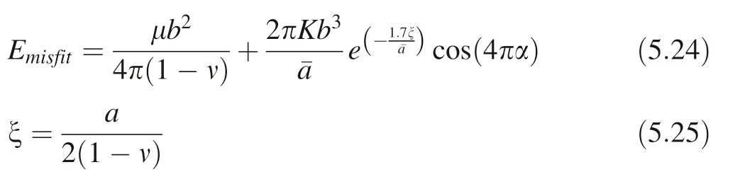
ζ: sliding dislocation core half-width; a: dislocation core width(cutting radius);μ:shear modulus;ν:Poisson’s ratio;α: relative slip distance, α ≤1;average energy barrier spacing (node spacing); K: dislocation direction factor,θ: the angle between the burgers vector and the dislocation line(since the angle between the dislocation line of the edge dislocation and the Burgers vector is equal to 90°, the angle between the dislocation line of the screw dislocation and the Burgers vector is equal to 0°, dislocation loop as a mixed dislocation, consists of edge dislocations and screw dislocations, we simplify that the value of θ is equal to 45°). The dislocation generation entropy Sgen(the crystal plastic deformation process is instantaneously completed due to cavitation erosion,so the dislocation entropy of thermal fluctuations is not considered. We presume that dislocation loops are in the same size in one plastic deformation process), including the dislocation configuration entropy Sconfig(Galindo 2013)and heat generation entropy Sgen-his:

a: atomic spacing; ndis: number of possible dislocations;Sgen-h: dislocation generates thermal entropy; A: the area of crystal plastic deformation zone which is perpendicular to the dislocation line; R: dislocation loop radius. The further calculation for A is:

A′: the area of the plastic deformation zone perpendicular to the dislocation line of each point on the dislocation loop(Here we assume that A′is approximately equal to the area of the spherical cap in the plastic strain zone:

Here still based on the classical Peierls-Nabarro stress dislocation model, when the applied stress σ=0, the dislocation glide energy Uglid|σ=0is equivalent to the lattice slip energy barrier, Peierls’ obstacle (Gang 2005):

Dislocation gliding energy barrier can also be written in the form of the classic Arrhenius (Lager et al. Lager et al.1982)

Finally, dislocation glide energy Uglidis:
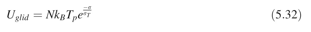
kB: Boltzmann constant; Tp: activation temperature; σ:applied stress; σT: Taylor stress, obtained by Taylor relationship formula (Rusinek and Klepaczko 2009) when applied stress equals to the flow stress σflow;N:the number of equivalent atoms in all lattices in the direction of glide per unit length (per meter) (Nn: the number of equivalent atoms in each crystal lattice, ¯a:gliding direction energy barrier spacing). There are considerable vacancies in the real crystal in the process of migration caused by dislocation glide, the interaction of dislocations and vacancy can lead to entropy changes:

Ωdis: microscopic state probability in the process of dislocation glide; Ωv-dis: microscopic state probability of dislocation and vacancy interaction in the process of dislocation glide. On the strength of the cavitation erosion of mineral crystal is only on the near-surface of the minerals, the vacancies are more susceptible to heat fluctuations and move away until they vanish.Therefore,ignoring the interaction between the hole and dislocation at the nearsurface, we can rewrite the formula (5.33) as following(Galindo 2013):

b:Burger’s vector model;ρ:average dislocation density;c:sound velocity in the crystal; ˙ε: plastic strain rate; Sglid-h:gliding thermal entropy. The total work and thermal entropy of the plastic deformation process caused by mineral crystal cavitation erosion are:
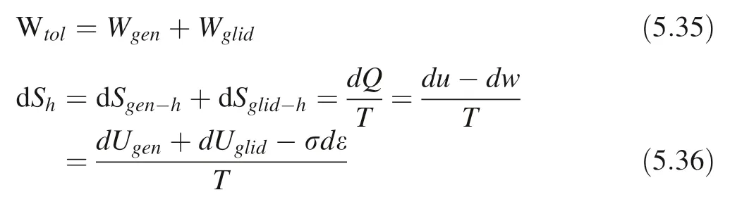

Here we use the average to simplify the calculation:: average thermal entropy;: average applied stress work;average internal energy;average temperature.¯ε: average strain.
Therefore, the Gibbs free energy change in the plastic deformation process of mineral crystals caused by cavitation erosion (the system does negative work) is:

The Gibbs free energy change that is coupled with the process of crystal plasticity deformation and mineral crystal dissolution in the process of cavitation erosion can be:

In Eq. (5.39),the total Gibbs free energy changes,Gibbs free energy changes in the process of plastic deformation and in the process of dissolution all of them are one mole.Nevertheless, we also need to determine the plastic strain rate ˙ε and temperature T in the instantaneous plastic deformation process of cavitation erosion mineral crystals. Here cavitation erosion of mineral crystals leads to instantaneous plastic deformation parallel to the surface direction of the crystal, which is much smaller than perpendicular to the surface direction. For simplicity, only the one-dimensional direction perpendicular to the crystal surface is considered.Because the plastic deformation of the crystal is caused by dislocation glide,the compressive strain rate ˙εpcan be obtained by the Orowan’s relationship formula (Langer et al. 2010):

˙γ: shear strain rate; γ: shear strain; ρ: dislocation average density; b: burgers vector (modulus); vd: dislocation glide speed. The dislocation glide speed (at non-very low temperatures) should satisfy the relationship (Langer et al.2010) that is:
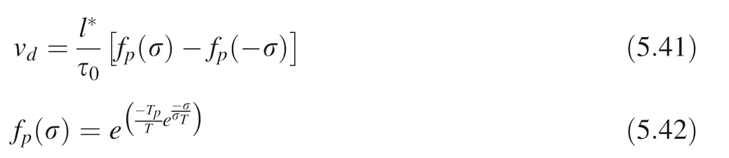
l*: dislocation mean free pathk proportional constant; in the initial stage of plastic deformation, k=but in the latter stage of linear work hardening stage k ≈(Galindo 2013;Bluma and Eisenlohr 2009);the attempt frequency (effective attack frequency), which is usually proportional to the Debye frequency, generally<0.01fD(Ryu et al.2011;Ulrich 2010);In the Debye model:, h: Planck constant; kB: Boltzmann constant; ΘD: Debye temperature. Here we consider the simple case:≈0.01fD. σT: Taylor stress, by Taylor relationship, σT=σflow. Because the gliding velocity of dislocation is determined by the both of dislocation glide energy barrier(potential trap)and applied stress in dislocation thermodynamics, when the energy provided by the applied stress is equal or greater than that of the glide energy barrier, dislocation glide commence.The dislocation glide energy barrier is mentioned by the preceding formula (5.31).

The activation temperature of dislocation is the lowest temperature to overcome the dislocation glide energy barrier without applied stress. Tp, it can be obtained from formula (5.31):

Therefore, the strain rate of plastic deformation is:
Finally, the temperature T of the instantaneous plastic deformation process of the crystal can be obtained by the energy conservation Eq. (2.33):

thus
As with all solid material deformation processes, the deformation process at the moment of cavitation erosion includes a more transient elastic deformation in the early stage (the elastic strain rate during elastic deformation is replaced by the average elastic strain rate. In the calculation process,the elastic strain time is set to 0.001 times the total deformation time.However,further calculations show that even 0.00001 or 0.1 times has little effect on the heat release and temperature distribution of the total deformation process). So Eq. (5.4) can be rewritten as:

In this experiment, the maximum pressure (maximum water hammer pressure)of the micro-jet at the solid–liquid interface during the cavitation erosion is approximately equal to the cubic-ZrO2flow stress, thus, pmax-wh=σ ≈σflow-ZrO2and the maximum pressure of the micro-jet at the solid–liquid interface is much greater than that of the α-SiO2flow stress, thus, the pmax-wh=σ ≫σflow-SiO2. (cubic-ZrO2initial and boundary conditions: T(x,0) = 308.0725 K;=0; α-SiO2initial and boundary conditions: T(x, 0) = 313.1114 K;
For cubic-ZrO2pmax-wh=σ ≈σflow-ZrO2, the temperature distribution of the plastic deformation process(that is,the temperature distribution when the applied stress is equal to the critical stress of plastic deformation) is shown as below (Figs. 4, 5, 6).
When α-SiO2pmax-wh=σ ≫σflow-SiO2, the change of temperature distribution in the α-SiO2plastic deformation process is shown below (Fig. 7).
Because the maximum pressure of the micro-jet at the solid–liquid interface is much greater than that of the α-SiO2flow stress, and the probability distribution of cavitation erosion obeys the Weibull distribution,which means that the micro-jet has a small probability of generating maximum pressure at the solid–liquid interface, we are more concerned about the change of temperature distribution when the applied stress equals to the α-SiO2flow stress(σ ≈σflow-SiO2), thus, the applied stress is equal to the critical stress of plastic deformation (Figs. 8, 9, 10).
Since the mineral phase transformation melting enthalpy is not considered in Eq. (2.33),when the temperature of the plastic deformation process is higher than the melting point of the mineral during the calculation, these high temperatures are merely theoretical values. Therefore, only the Gibbs free energy change at the highest temperature up to the melting point of the mineral is available here. Hereupon, we can evaluate the Gibbs free energy change(Table 5)caused by cavitation erosion plastic deformation.
The crystal dissolution rate based on chemical reaction transition State theory is:


Fig. 4 Change of temperature distribution in the cubic-ZrO2 plastic deformation process dislocation glide activation temperature of 9197.4940 K
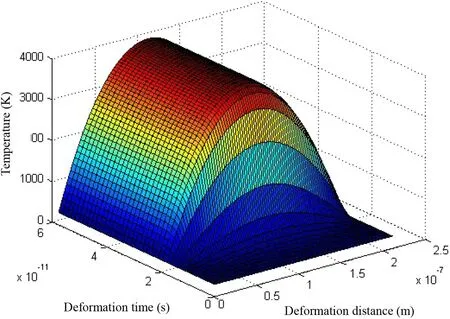
Fig. 5 Change of temperature distribution in the cubic-ZrO2 plastic deformation process dislocation glide activation temperature of 5006.4293 K
ΔG: mineral crystal dissolution Gibbs free energy change(related to dissolution process environmental solution saturation);A: dissolution constant,the reaction rate constant k(Susan et al.2008).(A=k=Arennius rate constant pre-exponential factor; Ea: reaction activation energy; kB: Boltzmann constant; T: thermodynamic temperature; h: Planck constant; ΔGTS: transition state complex Gibbs free energy change). Here, the reaction rate of the crystal dissolution process is linearly related to the saturation of the dissolution process in the nearequilibrium state (Lasaga and Luttge 2003)

Fig. 6 Change of temperature distribution in the cubic-ZrO2 plastic deformation process dislocation glide activation temperature of 1770.0575 K

Fig. 7 pmax-wh =σ ≫σflow-SiO2, change of temperature distribution in the α-SiO2 plastic deformation process when the dislocation glide activation temperature is 9541.7254 K

AP:activity product;Ksp:solubility product(Ke:dissolution equilibrium constant); s: saturation; ΔG: Gibbs free energy change of dissolution process. Then the cavitation erosion plastic deformation process total Gibbs free energy change:

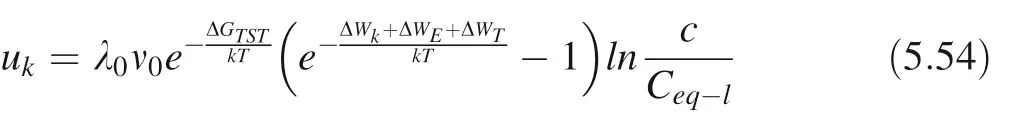
The instantaneous dissolution reaction rate of cavitation erosion plastic deformation process is (T1: theoretical plastic deformation maximum temperature or melting point temperature)

Fig. 8 σ ≈σflow-SiO2, change of temperature distribution in α-SiO2 plastic deformation process when the dislocation glide activation temperature is 9541.7254 K

Fig. 9 σ ≈σflow-SiO2, change of temperature distribution in α-SiO2 plastic deformation process when the dislocation glide activation temperature is 5009.9531 K

The dissolution rate of mineral crystals at room temperature T2= 298.15 K is:

The ratio of plastic deformation process reaction rate of cavitation erosion region to instantaneous reaction rate at room temperature is q(assuming that the reaction transition state complex Gibbs free energy variable ΔGTSchanges l ittle with temperature and the ionic activity product is equal in the dissolved solution)
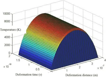
Fig. 10 σ ≈σflow-SiO2 conditions change of temperature distribution in α-SiO2 plastic deformation process when the dislocation glide activation temperature is 2660.0476 K

Substituting with saturation s

It can be learned from the above that when the transition state complex Gibbs free energy change ΔGTSincreased,the ratio of instantaneous reaction rate q in the same conditions also increased in exponential form. Although here the dissolution reaction rate Rate=A(1-in the dissolution process with Gibbs free energy is a linear relationship which has been confirmed in some mineral dissolution, still some minerals dissolve with its nonlinear relationship has been found:

For this kind of dissolution process, the instantaneous reaction rate ratio q also increases exponentially with m.For example, when the temperature of the plastic deformation process is reached at the melting point temperature T1=Tmelt=2988 K (corresponding dislocation activation temperature Tp=5006.4393 K), The ratio of cubic-ZrO2instantaneous dissolution reaction rate with saturation s(non-near dissolution equilibrium state) is as below(-Fig. 17, Table 8):

Table 5 Reaction of the plastic deformation process (the maximum temperature T is up to the melting point temperature) Gibbs free energy changes

Fig. 11 (Relevant dislocation activation temperature Tp =5006.4393 K) When the temperature of the plastic deformation process reaches the melting point temperature T1 =Tmelt =2988 K cubic-ZrO2.The instantaneous reaction rate ration q with saturation s(near dissolution equilibrium state)

Fig. 12 (Relevant dislocation activation temperature Tp =1770.0575 K) When the temperature of the plastic deformation process reaches the melting point temperature T1 =Tmelt =2988 K cubic-ZrO2.The instantaneous reaction rate ration q with saturation s(near dissolution equilibrium state)
All the above are the theoretical calculations and derivations of cavitation erosion leading to plastic deformation of mineral crystals to accelerate crystal transient dissolution. The results demonstrate that when the yield stress of the mineral crystal is greater than that water hammer pressure generated by the micro-jet caused by cavitation bubble collapse at the solid–liquid interface, the mineral crystal dissolution is not affected, such as magnesium spinel (MgAl2O4), Sapphire (α-Al2O3) in this experiment, otherwise, the elastic strain energy produced by the plastic deformation in the process of cavitation erosion on the surface of the crystal may promote the etching pit generating and step retreat (stepwaves expanding) of the crystal surface layer, but the mineral cubic zirconia (cubic-ZrO2) and α Quartz Sand (α-SiO2)theoretically are not supported, because of its relatively large nucleation radius (Hooker radius rh), or too large a surface free energy σ. Another important accelerated dissolution mechanism is that in the process of plastic deformation on the surface of mineral crystals, owing to instantaneous plastic deformation accompanied by a large amount of energy in the form of heat-releasing,resulting in the surface plastic deformation of the micro-region instantaneous high temperature, the surface dissolution of mineral crystals is accelerated (the plastic deformation process is accompanied by change in Gibbs free energy but it has little effect on high temperature accelerated dissolution of crystals).

Fig. 13 (Relevant dislocation activation temperature Tp =9197.4940 K) When the temperature of the plastic deformation process reaches max temperature T1 =305 K cubic-ZrO2. The instantaneous reaction rate ration q with saturation s(near dissolution equilibrium state)
In addition to the acceleration of the crystal transient dissolution by plastic deformation of the cavitation erosion,the continuous cavitation erosion cause material crack expands until the fracture and breaking,the bulk of mineral crystal can produce a large number of particles in the micron, submicron range with the different surface morphological patterns. Both the surfaces generated by the single crystal fracture and the polycrystalline mineral rock break were allocated substantial edges and convex. For micron-scale mineral particles with these surfaces, the dominance of the dissolution of mineral crystal depending on the Gibbs–Thomson effect should not be negligible.We consider the Gibbs–Thomson equation with the geometric characteristic factor, it is

Fig. 14 (Relevant dislocation activation temperature Tp =2660.0476 K) When the temperature of the plastic deformation process reaches the melting point temperature T1 =Tmelt =1713 K α-SiO2.The instantaneous reaction rate ratio q with saturation s(near dissolution equilibrium state)

Δμ: chemical potential in dissolution process; l: geometric characteristic length (radius of curvature);γ:interface free energy; Vm: molar volume; Ceq-l: dissolved equilibrium concentration (activity) when the geometric characteristic length is l;Ceq-∞dissolved equilibrium concentration(activity)when geometric characteristic length l is infinite;R: ideal gas constant; T: thermodynamic temperature; β:surface area geometric factor; α: volume geometric factor;(A=β l2;V =αl3;A:geometry surface area;V:geometry volumefor sphere:=3,r =l;r:radius of the sphere) (Wu and Nancollas 1999; Perez 2005).
In view of step or kink kinetics directly affect the dissolution process of mineral crystal surface, the dissolution of the Gibbs–Thomson effect can also be interpreted bymicroscopic steps and kinks kinetics of surface. Although the impurities or dislocations on the crystal terrace (flat plane) can be a source of pit nucleation, the etching pits come into being and the steps retreat away, and the crystal surface dissolve as a result from stepwave expanding at far from equilibrium state, but the kink kinetic mechanism of the edges and convex also plays an important role in all the stages of mineral crystal dissolution. (it can be more significant at near-equilibrium state, while the stepwave will be sharply weakened under near-equilibrium conditions)(Arvidson and Luttge 2010).

Table 6 Instantaneous dissolution reaction rate ratio of cubic-ZrO2 under the condition of maximum temperature (melting point temperature)during plastic deformation
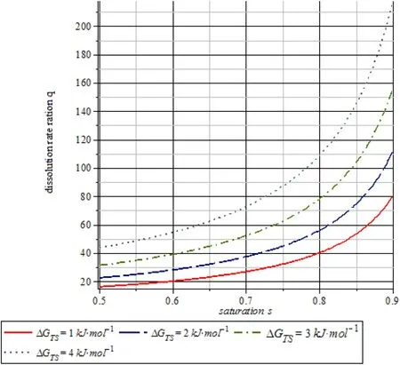
Fig. 15 (Relevant dislocation activation temperature Tp =5009.9531 K) When the temperature of the plastic deformation process reaches the melting point temperature T1 =Tmelt =1713 K α-SiO2.The instantaneous reaction rate ratio q with saturation s(near dissolution equilibrium state)

Fig. 16 (Relevant dislocation activation temperature Tp =9541.7254 K)When the temperature of the plastic deformation process reaches the max temperature T1 =318 K α-SiO2. The instantaneous reaction rate ratio q with saturation s (near dissolution equilibrium state)

Fig. 17 (m = 1–6, ΔGTS =4 kJ mol-1) (corresponding dislocation activation temperature Tp =5006.4393 K) When the temperature of the plastic deformation process reaches the melting point temperature T1 =Tmelt =2988 K cubic-ZrO2,the instantaneous reaction rate ratio q with saturation s (when the non-near equilibrium state) changes
Note that the kinks on the convex and edges of step have lower energy barrier of formation and the detachment rate of mineral crystal ions overwhelms the attachment rate at the most kink sites under the condition that the environment does not reach an equilibrium state, the ions will detach from the kinks on the convex and edges of step.Because the net detachment rate of ions gradually approaches zero until the dissolving equilibrium state, itcan also account for the relationship between saturation and dissolution of crystal. The velocity of step edge moving is

Table 7 Instantaneous dissolution reaction rate ratio of α-SiO2 under the condition of maximum temperature(melting point temperature)during plastic deformation

Table 8 Istantaneous dissolution reaction rate ratio under different reaction rate exponential factor m

ap: the length of a single atom perpendicular to the direction of the step edge; ρk:kink density,thus,the number of kinks on the stepped edge of the unit length,(Lasaga and Luttge 2004), uk: kink rate (the velocity of adding or subtracting one kink) on the unit length of step edge. Many experiments show that the relationship at the least, between near-equilibrium dissolution rate and the dissolution process Gibbs free energy change ΔG is linear.So we consider that the kink rate on the unit length of step edge is:

λ0: linear proportional coefficient; ν0: frequency factor;ΔWk=2φk: the work that crystal ions detaching from the site of kink; ΔWE=2φE: the work that crystal ions detaching from the step edge; ΔWT=2φT: the work that crystal ions detaching from terrace;ΔGTST:the free energy of single ion transition state complex in the crystal dissolution process; since single ion interplay with surrounding crystal ions with different energy.In this case,the different energy of interplaying can be described as:φk=γkaph,φk:the energy of interplaying with the kink region; γk: interface free energy in the kink region on the step edge,ap:the length of a single atom perpendicular to the direction of the step edge; h: the height of a single atom on the step edge;aE: the length of a single atom along the direction of the step edge;φE=γEaEh,the energy of interplaying with the step edge; γE: interface free energy on the step edge;φT=γTaEap, the energy of interplaying with the terrace;γT: interface free energy on the terrace (Tilbury 2017);environmental solution saturation.
Let us consider the Gibbs–Thomson effect, so the equation of kink rate can be rewritten as following:
We assume that the coefficient λ is

Fig. 18 The variation of the ΔG of the spherical α-SiO2 particles dissolution with the characteristic length l

Thereby, the velocity of step moving is

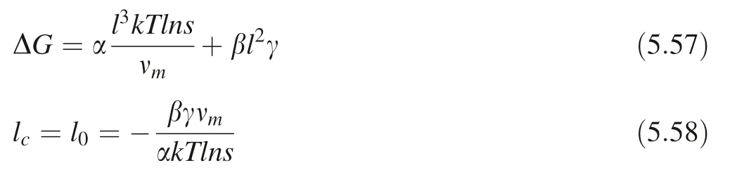
We should confine the geometric characteristic length l to a critical length lc, which is derived from the formula below(Wu and Nancollas 1999)(Fig. 18 is presented from the data of the spherical α-SiO2particle)νm: molecule volume. l0: zero-point characteristic length which is characteristic length when Gibbs free energy change of dissolution process equals zero. It is feasible to know that crystal surface dissolution will commence only when the geometric characteristic length exceeds the critical length lc,in the vicinity without defects or dislocation.This scenario is described by surface step edge shrinking and step retreating.
The characteristic lengths of different regions of the surface of the coarse-grained crystal particles are distributed in the range of lmin~lmax.Without considering the surface defects, the dissolution of the mineral crystals is simply caused by the kinking of the steps, which leads to the reduction of the step edges,and the retreat of the steps.
That is to say, the kinks are simultaneously moving to dissolve on the steps of the different characteristic lengths.For insoluble mineral crystals, the dissolution rate is much lower than the diffusion rate of the environmental solution,and even more so for the flowing water environment,so the dissolution rate is the overall dissolution rate at multiple characteristic lengths.

The unit kink length a in the edge direction is the unit characteristic length, l=na (only the isotropy is considered here,the distance that each kink moves one unit on the step edge is approximately equal to the inter-ions bond length b). We presume that the range of distribution(lc~lmax) is a continuous distribution (obviously f( l). is easy to satisfy the Dirichlet’s condition),the formula is as:

F ω( )=F f( l)[ ] is the Fourier transform of f( l), ω: corresponding (angular) frequency; j: imaginary unit. For the irregular crystal grain with a rough surface, the characteristic length distribution function is D( l). The step moving velocity function v( l) is

Now the overall dissolution rate with multiple characteristic lengths is( l) atom/s. It is assumed that the overall dissolution rate of the step edge movement under different characteristic lengths is linearly summation, so f( l) can be obtained by convolving v( l) with D( l):

F [ v(l) ]: is a v (l) Fourier transform form; F[ D (l) ]: is a D( l)Fourier transform form.
The rough surface irregular crystal particles can exhibit different geometric characteristic lengths at different observation scales. In the case of continuous cavitation erosion, the surface of the micron-size crystal particle is covered with a sub-micron-sized convexes or edges. For the large-sized particle such as a centimeter-level single crystal particle or a polycrystalline particle, their surfaces are covered with the micron-sized edges or convexes in which there are still covered with sub-micron small edges or convexes(they seem like fractal geometry).The number of them with the larger (middle) size characteristic length will increase as the crystal particle size.
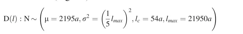
Here,for the sake of simplicity,since the particle size of the debris particles stemming from cavitation erosion is respectively in the level of micrometers and centimeters,the approximate characteristic length of the irregular crystal particles with a rough surface is characterized by a characteristic length distribution function D( l), we assume that it subjects to truncated normal distributionhe overall dissolution rate f( l) at multiple characteristic lengths is

The expectation of characteristic length (mean value) μ belongs to the sub-micron level.The variance σ2increases sharply as the particle size increases. We think that the environment is infinite, that is, the dissolution of mineral crystals does not influence the saturation of the environmental solution.
At the lattice of cubic-ZrO2, the Zr4+coordination number inside the crystal is 8(Fadda,et al.2009)therefore,the surface energy of the kink is approximately equal to 1/4 of the average surface energy of the mineral. The surface characteristic length distribution density function of the particles that generated by continuous cavitation erosion is as following (We assume that the corresponding solution saturation is 0.8, s = 0.8; ap=aE=h=b, b: Zr–O Bond length at the cubic-ZrO2; γaver:cubic-ZrO2Average surface energy.=54a) when the maximum particle size of cubic-ZrO2particles is 21950a(5 μm),we also assume that the characteristic length distribution function of the cubic-ZrO2surface convex is a truncated normal distribution (Fig. 19):
when the maximum particle size of cubic-ZrO2particles is 4390000a (1000 μm), we also assume that the characteristic length distribution function of the cubic-ZrO2surface convexes is a truncated normal distribution (Fig. 20):
The overall dissolution rate of multi-characteristic length of rough surface crystal particles obtained by convolution f (l)=v(l)*D( l), it is as following.

Fig. 19 The characteristic length probability distribution density function of the surface convex with a maximum particle size of 21950a (5 μm)
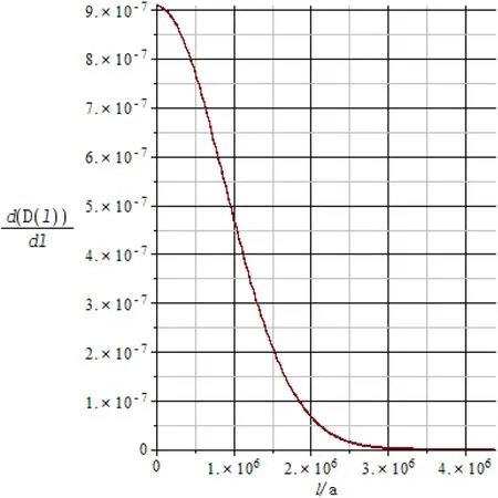
Fig. 20 The characteristic length probability distribution density function of the surface convex with maximum particle size of 4390000a (1000 μm)
Regardless of crystal anisotropy, we can estimate the activation energy of cubic-ZrO2dissolution process from the linear relationship of bond energy EZr–O, bond energy ESi–Oof α-SiO2crystal and SiO2dissolution activation energy:(Malherbe et al. 1986).ΔGTST≈Eact≈80.91 kJ/mol, γk=ap=aE=h=b, λ0=1, ν0=1012s-1, s = 0.8, T = 298 K) (Figs. 21, 22):

Fig. 21 The overall dissolution rate with the characteristic length distribution function of the cubic-ZrO2 surface convex is a truncated normal distribution D(l):N ~(μ =54a,lmax =21950a)s=0.8
We calculated the results as following,

The overall dissolution rate of the same volume of cubic-ZrO2particles is calculated by Zr4+atom,

The ratio of the overall dissolution rate of the same volume of cubic-ZrO2particles is:

We can also get the figure of cubic-ZrO2overall dissolution rate with the characteristic length l and saturation s(Fig. 23).
The Si4+coordination number is 4 in the α-SiO2tetrahedral crystal.; We assume that the corresponding solution saturation is 0.8,s = 0.8; ap=aE=h=b, b: Si–O Bond length at the α-SiO2; γaver: α-SiO2average surface energy. In the quartz dissolution process ΔGTST≈Eact=83.72 kJ/mol (Lasaga and Luttge 2004)when the maximum particle size of α-SiO2particles is 31645a (5 μm), we assume that the characteristic length distribution function of the α-SiO2surface convex is a truncated normal distribution:

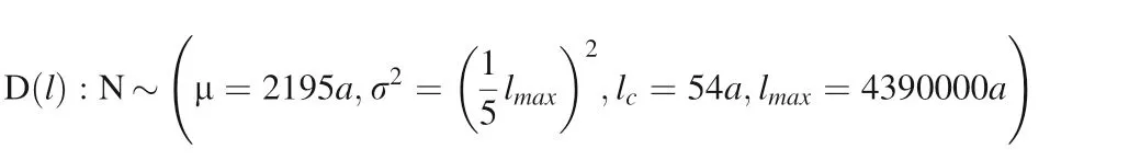
Fig. 22 The overall dissolution rate with the characteristic length distribution function of the cubic-ZrO2 surface convex is a truncated normal distribution D(l):N ~ μ=2195a,σ2 =54a,lmax = 4390000a)s=0.8
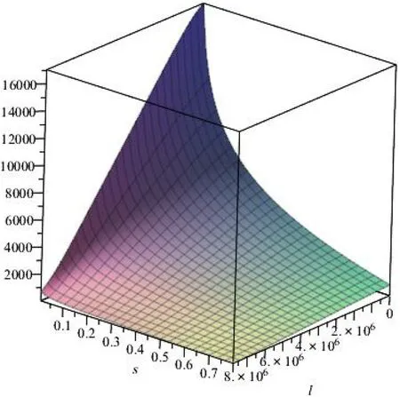
Fig. 23 The overall dissolution rate with the change of characteristic length l and saturation s[s:0.1-0.8,l:lc ~lmax,μ=2195a, σ2 =

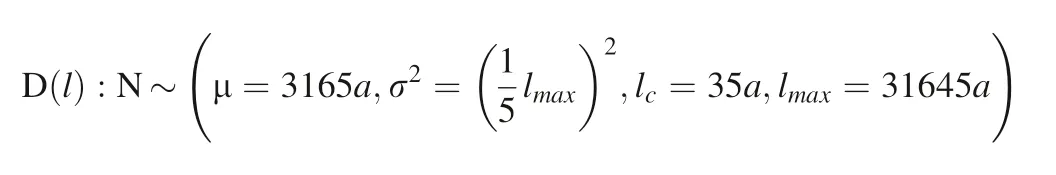
Fig. 24 The overall dissolution rate with the characteristic length distribution function of the α-SiO2 surface convex is a truncated normal distribution. D(l):N ~ μ=3165a,35a,lmax =31645a)s=0.8
The overall dissolution rate of multi-characteristic length of rough surface crystal particles is in Fig. 24.
When the maximum particle size of α-SiO2particles is 6329100a (1000 μm), we assume that the characteristic length distribution function of the α-SiO2surface convex is a truncated normal distribution,
The overall dissolution rate of multi-characteristic length of rough surface crystal particles is in Fig. 25.
We calculated the results as following,

The overall dissolution rate of the same volume of α-SiO2particles is calculated by Si4+atom

Fig. 25 The overall dissolution rate with the characteristic length distribution function of theα-SiO2 surface convex is a truncated normal distribution D(l):N ~[μ=3165a,35a,lmax =6329100a]s=0.8
The ratio of the overall dissolution rate of the same volume of α-SiO2particles is:
We can also get the figure of α-SiO2overall dissolution rate with the characteristic length l and saturation s(Fig. 26).
We can learn that when the saturation s is relatively low in the natural environment,the minerals fracture and break due to continuous cavitation erosion can generate micronsized crystal particles. At this point, the characteristic length l distribution of them is D( l)~(μ,σ2,lc,lmax),which strongly affects the dissolution of minerals with the Gibbs–Thomson effect.
5.2 Experimental results comparison and discussion
The experimental results of cubic zirconia (cubic-ZrO2)ultrasonic treatment are as following (Figs. 27, 28), in which (3, y), (2, y), y:1,2,3 parallel sample number.

Fig. 26 The overall dissolution rate with the change of characteristic length l and saturation s[s:0.1-0.8,l:lc ~lmax,μ=3165a,σ2 =
In the light of concentration of Zr4+in the ultrasonic treatment experimental group was similar to that of the non-ultrasound control group (including diameter φ = 0.8 mm cubic-ZrO2monocrystalline granules control group and large single crystal control group concentration of Zr4+)and the concentration of Zr4+in the experimental group was significantly negatively correlated with the temperature of sampling (The Pearson correlation coefficient (average) of the parallel sample (3, y) concentration and the temperature of sampling was - 0.98, and the Pearson correlation coefficient (average) of the parallel sample(2,y)concentration and the temperature at the time of sampling was - 0.82, both of which were significantly correlated on the double side of the 0.05 level) we can speculate that the concentration of the experimental group is only affected by the thermal fluctuation of the environment (mineral, glass surface ions adsorption thermal fluctuation difference, because far from the dissolution balance, there is no saturation precipitation).
Diameter φ = 0.8 mm cubic-ZrO2monocrystalline granules experimental group (1158, total mass equal to a large cubic zirconia single crystal) whose concentration of Zr4+was 1.73 times that of the non-ultrasound large control group control group (sampling at the same temperature), while the total surface area of 1158 φ = 0.8 mm particles is 7.4 times that of the large cubic zirconia single crystal. Although it can be considered that the probability of cavitation erosion of mineral crystals is proportional to the surface area, but the threshold value of plastic deformation (yield stress) of cubic-ZrO2is higher enough (the theoretical calculation is approximately equal to the maximum water hammer pressure produced by cavitationbubble micro-jet and the relevant cavitation probability can approach the Weibull distribution minimum value of exponential decreasing).Therefore,the plastic deformation probability of cavitation erosion is too small so that the increase of cubic-ZrO2dissolution is not obvious (but the concentration of Zr4+in the solution is much smaller than the dissolved equilibrium concentration,so it is still limited by the dissolution rate).


Fig. 28 Number of ultrasonic treatments and changes in zirconium ion concentration in cubic zirconia solution
For Spinel (MgAl2O4) and Sapphire (α-Al2O3), the change in Si4+concentration is more significant than the change in Al3+concentration (Figs. 29, 30). Its large amount of silicon may only stem from the experimental silicate glass beaker(it is impossible that the interior of the gem-quality spinel and sapphire contains a large number of silicon impurities and dissolves). Almost the same concentration of Al3+, Si4+in the same number of ultrasonic treatment of cubic-ZrO2solution can better illustrate this point. Consequently, we can be sure that ultrasonic treatment cavitation erosion accelerates the dissolution of silicate glass, even if the glass as an amorphous substance,can also undergo plastic deformation caused by cavitation erosion, which accelerates dissolution.
Compared with sapphire, pure α-Al2O3single crystal,industrial white corundum sands as α-Al2O3contain some impurities α-SiO2. The concentration of Si4+from the industrial white corundum sands experimental group showed a significant increase with the increasing number of ultrasound treatments, while the control group solution Si4+had almost no change (Figs. 31, 32). Similarly, the Al3+also increased with the increase of ultrasonic treatment and the Al3+in the control group had little change,and the change of Al3+concentration was less than two orders of magnitude compared with the change of Si4+concentration (Figs. 31, 32). There are a large number of impurities and their own defects in the white corundum sand α-Al2O3relative to the sapphire, pure α-Al2O3monocrystalline, its yield stress will decrease if a few silicon atoms or other heteroatoms enter the α-Al2O3lattice.Another more striking phenomenon is that white corundum sands continuously produce a great deal of micron-sized particulate debris during ultrasonic treatment. Consequently, the Gibbs–Thomson effect may prominently enhance the dissolution of mineral crystals. For all those reasons, the dissolution rate can increase significantly.

Fig. 29 Number of ultrasonic treatment and changes of aluminum–silicon ion concentration in spinel solution

Fig. 30 Number of ultrasonic treatment and changes of aluminum–silicon ion concentration in sapphire solution

Fig. 31 Changes of aluminum silicon ion concentration in the number of ultrasonic treatments and white corundum sand(including α-SiO2 impurities)
6 Conclusion
Even though the above experimental results cannot quantitatively verify the theoretical calculation results that cavitation erosion accelerated mineral crystal dissolution,at present, it can be qualitatively explained the theoretical mechanism of it. The threshold value of plastic deformation (yield stress) of cubic-ZrO2is approximately equal to the maximum water hammer pressure between solid–liquid interfaces.The very low probability of plastic deformation caused by cavitation erosion makes the increase of cubic-ZrO2dissolution not significant, but the dissolution rate still increases. The changes of dissolved ions were not observed in magnesium spinel(MgAl2O4)and sapphire(α-Al2O3)in the experiment and in which the changes of Si4+,Al3+concentration both come from the dissolution of silicate glass. These verify that the yield stress is much greater than the water hammer pressure produced by the micro-jet produced when cavitation bubble collapse between the solid–liquid interface,so that the dissolution of mineral crystals are not affected.The α-Al2O3of industrial white corundum sands containing some α-SiO2impurities exhibit differential dissolution of Si4+and Al3+in the experiment of ultrasonic cavitation erosion, which is also verified that the threshold value of plastic deformation(yield stress) of α-SiO2in theoretical calculation is much smaller than the maximum of water hammer pressure between solid–liquid interface, hence, relevant plastic deformation accelerates the α-SiO2dissolution. (compared with the Si4+concentration of the glass source in cubic zirconia,magnesium spinel and sapphire solution,the Si4+dissolved from α-SiO2is two orders of magnitude higher),while the white corundum sand containing impurities is compared with the Sapphire single crystal, dissolution rate increases to a certain extent, and the yield stress of some grains decreases to a certain extent, but the main body is still much larger than the theoretical calculation of the water hammer pressure produced by the micro-jet between the solid–liquid interface, both the above lead to a significant difference between Si4+and Al3+dissolution concentration (two orders of magnitude difference). While,under conditions that the continuous cavitation erosion causes material crack expands until the fracture and breaking, the bulk of mineral crystal (white corundum sands in this experiment) can produce a large number of particle debris in the micron, submicron range, consequently, the Gibbs–Thomson effect may enhance the dissolution of mineral crystals more prominently.It is definite that the cavitation erosion mechanism of accelerating mineral crystal dissolution must be subtle and complicate.The derivation from the theoretical calculation in this paper is a preliminary study and a lot of details should be concerned, such as the impact of the shock wave generated during the cavitation erosion process for mineral dissolution,mineral anisotropy,whatever,they are also worthy of further study.
AcknowledgementsThis work is financially supported by Key Research of Frontier Science, CAS, Grant. NO. QYZDY-SSWDQC010.

Fig. 32 ratio of ultrasonic processing times to aluminum–silicon ion concentration in white corundum sand(including α-SiO2 impurities)
Appendix
The Cubic-ZrO2physical properties from literature (Argyriou 1994; Arima et al. 2004; Chistyi et al. 1977;Degueldre et al. 2003; Gogotsi et al. 1995; Jean and Daniele 2000; Michael et al. 1982; Muhammada et al.2014; Zhang 2007; Sotiropoulou and Nikolopoulos 1991;Takeo et al. 1999; Zhao et al. 2011); α-SiO2physical properties from literature(Alireza et al.2010;Barron et al.1982; Bengt and Rajeev 1999; Fredric et al. 1989; George 1984; Heinisch et al. 1975; Blacic 1984; Paul et al. 2003);MgAl2O4physical properties from literature (Askarpour et al. 1993; Burghartz and Schulz 1994; Ganesh 2013; Cai et al. 2006; Raja and Thomas 1977; Razvan and Edward 2009;Slack 1962;Suzuki et al.2000;Laag et al.2005);α-Al2O3physical properties from literature (Burghartz and Schulz 1994; Slack 1962; Holm et al. 1999; Levi and Kaplan 2003;Snow and Heuer 1973).Reference of melting enthalpy and heat capacity (John 1999); cubic-ZrO2, α-SiO2dissolution equilibrium constant Ke(solubility product Ksp) (Table 9):


Cubic-ZrO2, α-SiO2dissolution reaction process Gibbs free energy change from literature(Dennis 1983;Ingvi and Stefa´n 2000).

There are two trends of acid ionization and alkaline ionization in neutral aqueous solution, so the hydration ionization cubic-ZrO2contains not only acid ionization product Zr (OH )+3, but also alkaline ionization productand electrically neutral product Zr (OH )4(aq ).
The Zr–O bond length in the cubic-ZrO2crystal(Zhang 2007). The Si–O bond length in the α-SiO2crystal (Lager et al. 1982).

Table 9 Data source of physical properties of mineral crystals used in calculations (ambient temperature is 298 K)
杂志排行

Acta Geochimica的其它文章
- Chemical structure of the Earth’s mantle defined by fast diffusion elements like helium
- A helium stratified and ingassed lower mantle: resolving the helium paradoxes
- Zircon chemistry and new laser ablation U-Pb ages for uraniferous granitoids in SW Cameroon
- Zircon U-Pb age and geochemical constraints on the origin and tectonic implication of the Tuotuohe Cenozoic alkaline magmatism in Qinghai-Tibet Plateau
- Evaluation of the potential risks of heavy metal contamination in rice paddy soils around an abandoned Hg mine area in Southwest China
- Low-temperature alteration of uranium-thorium bearing minerals and its significance in neoformation of radioactive minerals in stream sediments of Wadi El-Reddah, North Eastern Desert, Egypt