Rotation of dust vortex in a metal saw structure in dusty plasma
2020-04-24ChaoxingDAI戴超星ChaoSONG宋超XueGUO郭雪WentaoSUN孙文涛ZhiqiangGUO郭志强FuchengLIU刘富成andYafengHE贺亚峰
Chaoxing DAI (戴超星),Chao SONG (宋超),Xue GUO (郭雪),Wentao SUN(孙文涛),Zhiqiang GUO(郭志强),Fucheng LIU(刘富成) and Yafeng HE (贺亚峰)
Hebei Key Laboratory of Optic-electronic Information Materials,College of Physics Science and Technology,Hebei University,Baoding 071002,People’s Republic of China
1 Authors to whom any correspondence should be addressed.
Abstract
Keywords:dusty plasma,vortex,directional rotation
1.Introduction
Dusty plasma consists of electrons,ions,neutral gas atoms,or molecules,and dust grains [1–15].In the laboratory plasma environment,these dust particles are charged via collisions with electrons and ions and can acquire charges of the order of 103to 105elementary charges.Highly-charged dust particles can exhibit strong coupling effects,which could further give rise to many novel physical phenomena such as dust crystal lattices,phase transitions,and dust sound waves [16–19].The dust particles can be easily tracked by a camera in experiments,which makes it an ideal model system for studying the phase transitions and the nonlinear wave phenomena and so on.
Vortex motion of dust particles is an important research topic in dusty plasma [20–26].It has been observed in dusty plasma both under microgravity and on the Earth.A plurality of co-rotating (clockwise and counterclockwise) dust vortices appeared in the dense dust cloud,and a phenomenon of conversion from a plurality of vortex to a single vortex was observed when the discharge power was reduced [20].Clockwise and counterclockwise dust vortices appeared simultaneously on the edge of the cloud [21].The occurrence of these vortices was explained on the basis of the charge gradient of dust particles which was orthogonal to the ion drag force [20–26].The charge gradient was a consequence of the plasma inhomogeneity along the dense dust cloud length.Two-dimensional dust vortex generated by asymmetric potential structures has also been observed in DC discharge plasmas [23].A mechanism of the dust vortex generation was explained by the effect of an asymmetry of ion drag force near the metal plate[23].However,most of those vortices occur in the form of a couple of co-rotations or in the vertical plane.In recent years,we have realized a single vortex with an asymmetrical resin saw structure in rf discharge plasma (horizontal) [26],in which only positive rotation of dust vortex was observed.The saw structure breaks the symmetry of system in the azimuthal direction,which could give rise to a net ion drag to drive the dust vortex.In this work,we design an asymmetric metal saw structure,and obtain both negative and positive rotations of dust vortices.The transition between the negative and positive rotations of dust vortices is reversible and controllable by changing the plasma parameters.We also discuss the underlying mechanism of this transition.
2.Experimental setup
The experiments are performed in a vacuum chamber filled with argon as shown by the schematic diagram in figure 1.Argon gas flows at a rate of 10 sccm and the gas pressure changes within the range of 20–180 Pa.The upper electrode is the ITO glass plate and is grounded,the lower electrode is stainless steel plate which is connected to an rf power.The distance between the two electrodes is 40 mm.The dust particles used for the experiments are macro-porous cross-linked polystyrene microspheres with a diameter of 23 μm and a massmd≈ 4.5 ×10⁻¹²kg.After the plasma is ignited,dust particles are dropped into the center of the saw structure.They are levitated at about 5 mm above the lower electrode.A metal saw structure placed on the lower electrode(see figure 1)is used to confine the dust particles to move in the horizontal plane.The dust particles are illuminated by a flashlight from side of the vacuum chamber and the movements of dust particles are recorded by a camera placed on the top of the vacuum chamber.The trajectories and velocities of dust particles are obtained by using developed video processing programs.
The metal saw structure having 20 sawteeth is made of stainless steel.The depth of the saw structure gear is 3 mm.The radius and height of the saw structure are 13 mm and 5 mm,respectively.The metal saw structure is horizontally placed on the lower electrode,therefore,it has the same electric potential with the lower electrode.This is very different from our previous experiments with resin saw structures,in which the electric potential of the resin saw structure is float one and is generally much smaller than that of the lower electrode.
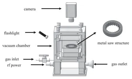
Figure 1.Schematic diagram of the experimental setup.The upper right corner is a magnified view of the metal saw structure.The radius and height of the metal saw structure are 13 mm and 5 mm,respectively.The depth of the sawtooth of the metal saw structure is 3 mm.The sawtooth number of the metal saw structure is 20.
3.Experimental results
When dust particles are introduced into the plasma,they are electrostatically suspended above the lower electrode to form dust vortex as shown in figure 2.Here,we call the rotating dense dust cloud (figure 2(a)),the rotating dust void(figures 2(b)and(c))and the rotating dust chain(figure 2(d))as dust vortices.Because the saw structure has asymmetry in azimuthal direction,it gives rise to azimuthal actions including static electricity of the sheath and ion drag,which could drive the dust vortex to rotate under appropriate conditions.As our main results,here,we observe both positive and negative rotations of dust vortex,i.e.,clockwise and anticlockwise rotations as indicated in figure 2(a).The positive and negative rotations of dust vortex could convert each other,and the direction of rotation can be controlled by changing the gas pressure and the power as we shown below one by one.
Firstly,we focus on the spatial distribution of dust vortex in the saw structure as changing the control parameters.Figure 2 shows the spatial distributions of dusty vortices in the horizontal plane with increasing gas pressure.At low gas pressure,dust particles are distributed at the center of the saw structure,which forms a dense dust cloud,as shown in figure 1(a).The levitation height of dust particles above the lower electrode is z=4.5 mm.When the gas pressure increases to about 33 Pa,a clear void,local dust-free region,appears at the center of the dust vortex,as shown in figure 2(b).The levitation height of dust particles decreases to z=3.7 mm.By increasing the gas pressure further,the dust void expands outward until a dust chain forms,as shown in figure 2(d).The levitation height of dust particles is close to the lower electrode z=2.7 mm.The evolution from the dense dust cloud to the dust void as increasing the gas pressure in this metal saw structure (figure 2) is very similar to that in a resin saw structure [26].The underlying mechanism of those evolutions is that enhancing the gas pressure results in an increase of the plasma potential and a reduction of the sheath thickness.By increasing the gas pressure,the balance position of dust particle in horizontal plane approaches the saw structure [27],therefore,a dust void appears.
Figure 3 shows the dependence of the diameters of the dense dust cloud and the dust void on the gas pressure at 25 W.It is clearly shown that the diameter of dust cloud increases,from 3.4 to 18.4 mm,with the gas pressure from 22 to 170 Pa.When the gas pressure reaches about 33 Pa,a void appears in the center of the dense dust cloud as shown in figure 2(b).The diameter of the dust void increases quickly with the gas pressure as indicated by the dashed line in figure 3.When the gas pressure approaches about 60 Pa,the solid line and the dashed line overlap(figure 3),which means that a single dust chain forms as shown in figure 2(d).The expansions of the dense dust cloud and the dust void with increasing the gas pressure in this metal saw structure are similar to that in resin saw structures[26].Note,when the gas pressure is higher than 170 Pa,the plasma sheath becomes very thin,the dust chain breaks and the dust particles enter the saw groove (not shown here).
Figure 4 shows the evolution of the dense dust cloud and the dust void as a function of rf power.At lower rf power,the diameters of the dense dust cloud and the dust void increase quickly with the rf power.The expansion of the dust void is faster than that of the dense dust cloud.When the rf power exceeds about 10 W,the rf power has less influence on the dense dust cloud and the dust void.
We then focus on the dynamical rotation of dust vortex in the metal saw structure.Figure 5 shows the dependence of the average angular velocity of the dust vortex on the gas pressure.It is clearly shown that the average angular velocity varies non-monotonically with the gas pressure.When the gas pressure is around 60 Pa,the average angular velocity reaches a maximum of about 0.42 rad s-1.Remarkably,when the gas pressure is lower than 33 Pa,the average angular velocity is less than zero,which leads to a negative rotation of dust vertex.Therefore,increasing the gas pressure from 22 to 170 Pa,the dust vortex rotating negatively slows down firstly until it stops,then it performs positive rotation.Note,from our observation,the transition between the negative and positive rotations of dust vortices is reversible by changing the gas pressure/input power.It means that the rotation direction of dust vortex can be manipulated by varying the experimental conditions.The observed dust vortex in this metal saw structure is very different from that formed in resin saw structure [26],in which only positive rotation of dust vortex was obtained.
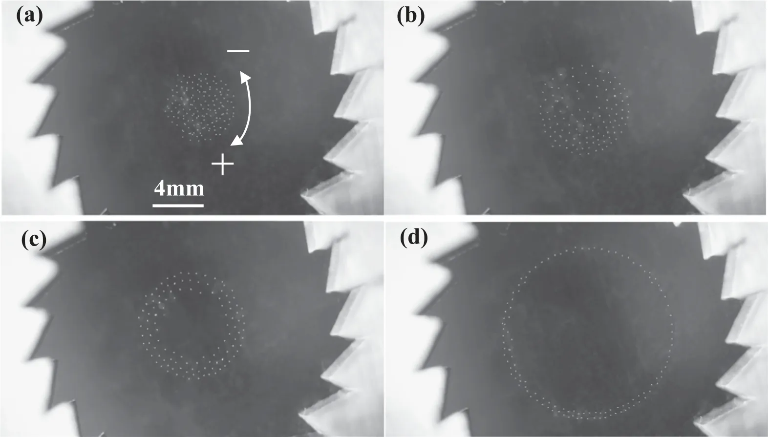
Figure 2.Spatial distributions of dusty vortices in the horizontal plane at different gas pressures.(a) Dense dust cloud,P=25 Pa,z=4.5 mm;(b)critical dust void,P=33 Pa,z=3.7 mm;(c)dust void,P=35 Pa,z=3.6 mm;(d)dust chain,P=60 Pa,z=2.7 mm,here,P is the gas pressure,z is the levitation height of dust particles above the lower electrode.Power:25 W.

Figure 3.Dependence of the diameters of the dense dust cloud and the dust void on the gas pressure at 25 W.

Figure 4.Dependence of the diameters of the dense dust cloud and the dust void on the power at 50 Pa.
When the gas pressure exceeds 170 Pa,as shown above,the dust chain breaks and the dust particles enter the saw groove.In this case,the dust vortex disappears.
Figure 6 shows the dependence of the average angular velocity of the dust vortex on rf power at the given gas pressure of 35 Pa.The average angular velocity of dust vortex increases monotonously from −0.29 to 0.29 rad s−1by increasing the rf power.The average angular velocity as a function of rf power can be fitted by a straight line as indicated in figure 6.Note,there is no correlation between the appearance of dust void and the reversal of the rotation direction of dust vortex (as can be seen in figure 7).In figure 6,the dust void appears at about 10 W,however,the transition between the negative and positive rotations of dust vortices occurs at about 30 W.
Figure 7 shows two critical lines which separate the dense dust cloud and the dust void,and the negative and positive rotations of dust vortices,respectively.It can be seen that,at larger gas pressure and higher input power,one can obtain positive rotation of dust vortex with void,and vice versa.The two critical lines intersect at 33 Pa,25 W,which is close to the critical point separating the dense dust cloud and dust void,and the negative and positive rotations in figure 5.
The designed saw structure is characterized by the asymmetric sawtooth which can lead to the confinement to dust particles in both radial and azimuthal directions.In the radial direction,just like the grove in the electrode and the ring used in most experiments,the saw structure confines the dust particles into its center via the electric field of the sheath.When the gas pressure is very low,the thickness of the sheath of the saw structure is large.Due to the smaller radius of the saw structure,a parabolic potential resulting from the sheaths of the saw structure appears,which confines the dust particles in the center of the saw structure,then,the dense dust cloud forms as shown in figure 2(a).With the increase of the gas pressure,the sheath of the saw structure becomes thin.When the thickness of the sheath of the saw structure is less than the radius of the saw structure,radial ion drag to the dust particles becomes strong.Therefore,the dense dust cloud is pushed outward by the stronger ion drag from the center of the saw structure,which results in the formation of the dust void,as shown in figures 2(b)–(d).
In the azimuthal direction,the asymmetry of the saw structure gives rise to an asymmetric electric potential and ion drag which can drive the dust vortex to rotate [26].The asymmetric electric potential along the azimuthal direction exhibits a feature of ratchet potential which is the origin of the directional rotation of the dust vortex.Here,in this metal saw structure,we obtain both negative and positive rotations of dust vortices.It means that the orientation of the asymmetric ratchet potential would reverse when we changing the gas pressure/power,which further results in the reversal of rotation directions of dust vortices.This reversal of the rotation direction of the dust vortex as changing the plasma parameters is very similar to that of the directional flow of dust particles in a dusty plasma ratchet[28].In[28],we found experimentally both negative and positive flows of dust particles along a saw channel.By using COMSOL simulations,we explored the underlying mechanism of the reversal of the flow of dust particles in detail.From numerical simulations,we found that the levitation height of dust particles is very different and the orientation of the ratchet potential could reverse at different plasma parameters,which further leads to the reversal of the flow of dust particles.In this metal saw structure,we believe that the reversal of the rotation directions of dust vortices also originates from the reversal of the asymmetric ratchet potential along the azimuthal direction,which will be studied numerically in our future work.

Figure 5.Dependence of the average angular velocity of the dust vortex on the gas pressure at 25 W.
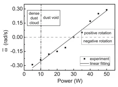
Figure 6.Dependence of the average angular velocity of the dust vortex on the power at 35 Pa.
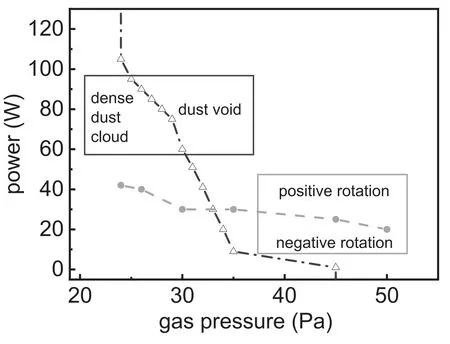
Figure 7.Transition lines of no-void and void(empty triangles),and the negative and position rotations of dust vortices (filled circles).
4.Conclusion
In this work,we observed dust void appearing around the center of the dense dust cloud while increasing the gas pressure.We also obtained both negative and positive rotations of dust vortices by using a metal saw structure.The rotation direction of dust vortex can be controlled by adjusting the gas pressure/power of discharge.As increasing the gas pressure/power,negative rotation of the dust vortex turns continuously into positive rotation.The underlying mechanism of the reversal of the rotation direction of the dust vortex was explored based on the analysis of the asymmetric action of electric potential and ion drag in the saw structure.Our results are helpful for understanding well the dynamical mechanisms of dust vortex in the dusty plasma.
Acknowledgments
This work is supported by National Natural Science Foundation of China (No.11975089),the Program for National Defense Science and Technology Innovation Special Zone,and the Program for Young Top-Notch Talents of Hebei Province,and Hebei Natural Science Fund (Grant No.A2017201099).
ORCID iDs
猜你喜欢
杂志排行

Plasma Science and Technology的其它文章
- DBD coupled with MnOx/γ-Al2O3 catalysts for the degradation of chlorobenzene
- Investigation on pulsed discharge mode in SF6-C2H6 mixtures
- Temporal evolution of atmospheric cascade glow discharge with pulsed discharge and radio frequency discharge
- How bead shapes affect the plasma streamer characteristics in packed-bed dielectric barrier discharges:a kinetic modeling study
- Comparative analysis of the arc characteristics inside the convergingdiverging and cylindrical plasma torches
- 1,2,4-trichlorobenzene decomposition using non-thermal plasma technology