Temporal evolution of atmospheric cascade glow discharge with pulsed discharge and radio frequency discharge
2020-04-24QianhanHAN韩乾翰ChenyuWU武晨瑜YingGUO郭颖andJianjunSHI石建军
Qianhan HAN (韩乾翰),Chenyu WU (武晨瑜),Ying GUO (郭颖),2,3 and Jianjun SHI (石建军),2
1 College of Science,Donghua University,Shanghai 201620,People’s Republic of China
2 Member of Magnetic Confinement Fusion Research Center,Ministry of Education of the People’s Republic of China,Shanghai 201620,People’s Republic of China
3 Shanghai Center for High Performance Fibers and Composites,Center for Civil Aviation Composites of Donghua University,Shanghai 201620,People’s Republic of China
Abstract
Keywords:atmospheric cascade glow discharge,pulsed discharge,radio frequency discharge
1.Introduction
Nonthermal plasmas generated by atmospheric glow discharge can be employed in the applications of surface modification[1–3],biomedicine[4–6],and deposition[7–9],et al.As the vacuum system is not necessary for the generation of atmospheric plasmas,it is suitable for online processing in industries,which encourages research on atmospheric plasma source developments and applications[10,11].However,the discharge stability and uniformity are difficult to achieve due to the high gas breakdown voltage at atmospheric pressure,which limits their applications.Dielectric barrier discharge(DBD) with electrodes covered with dielectric layers can generate the stable atmospheric glow discharges in the form of pulsed discharge[5],which can also be excited by the submicrosecond pulsed voltage [1].In pulsed discharges,the discharge instability is avoided by switching off the discharge within sub-microsecond.The stable atmospheric glow discharges can also be obtained with radio frequency(RF)glow discharge,in which,the plasma species are confined in the plasma bulk [7].Recently,the pulse modulated (PM) RF glow discharge was developed to manipulate the discharge characteristics in terms of discharge intensity and gas temperature,which were dependent on the discharge ignition dynamics of RF discharge [12].By introducing a pulsed discharge between the successive RF discharge bursts in pulsed modulated RF discharges,the discharge is named as cascade discharge and the ignition of RF discharge is enhanced by pulsed discharge with reduced ignition time[13,14].On the other hand,the uniformity of atmospheric glow discharge is not well addressed,especially along the electrode surface,which is an important issue in most applications [15,16].

Figure 1.Schematic of the experimental setup.
In this experiment,the indium tin oxide (ITO) glass was employed as the transparent electrode to capture the discharge distribution along the electrode surface.In the cascade discharge with a pulsed discharge between the successive RF discharge bursts,the spatio-temporal evolutions of discharge along the electrode surface and interelectrode gap are investigated by time resolved discharge images,and the influence of pulsed discharge on RF discharge ignition is also studied by controlling the time interval between pulsed discharge and RF discharge burst,which is discussed with the effects of residual plasma species from pulsed discharges on RF discharge.
2.Experimental setup
The experimental setup is shown in figure 1.A stainless steel electrode with a diameter of 2 cm was connected to the pulsed power.A glass plate with the thickness of 1 mm and size of 10×10 cm2was coated with an ITO layer with thickness of 400 nm and surface conductivity of 2×10³S m−1,which was connected to the RF power.The discharge is generated between the stainless steel electrode and the glass plate with the gap distance of 2.5 mm,in which,the glass plate acts as the dielectric barrier above the transparent ITO electrode.The electrodes are enclosed in a Teflon box filled with helium gas(99.999%) with a flow rate of 2.5 SLM at 760 Torr.A signal generator (Tektronix AFG 3102) to generate two synchronized 5 kHz pulse signals,the first pulse signal with the duty cycle of 0.5% is used to control the pulsed discharge system and the enhanced charge coupled device (ICCD) camera(Andor i-Star DH734).The pulsed discharge system consists of a direct current high voltage power supply(SL 2000)and a pulse switch (DEI PVX-4110).The ICCD camera photographed the discharge from the side view and the top view,respectively.The second pulse signal with the duty cycle of 50% is used to modulate the 12 MHz RF signal generated by another signal generator (Tektronix AFG 3102).The modulated RF signal is connected to a power amplifier(AR150A100B)and connected to the ITO electrode through a matching network.Voltage and current waveforms were measured using a voltage probe (Tektronix P6015A) and a current probe (Pearson 2877) and recorded with a digital oscilloscope (Tektronix TDE 3034C).The discharge appearance from the side view and the top view was taken by the ICCD camera triggered by the synchronized pulse signal.

Figure 2.Waveforms of (a) voltage and (b) current of a pulsed discharge and PM RF discharge.

Figure 3.Voltage and current waveforms of a pulsed discharge.
3.Results and discussion
Figure 2(a) shows the voltage waveforms of the pulsed discharge and PM RF discharge.The time instant of zero is the trigger time of ICCD camera.The pulse voltage and PM RF voltage were applied at the time instants of 0.2 μs and 11.2 μs,respectively.The corresponding discharge current waveforms are given in figure 2(b).The amplitudes of voltage and current during RF discharge stable operation are 480 V and 100 mA,respectively.The detailed waveforms of pulsed discharge voltage and current are presented in figure 3.The pulsed width is 1 μs and the amplitude of pulse voltage is 1.2 kV.There are two discharge events at 0.2 μs and 1.2 μs,corresponding to the rising and falling edges of the pulse voltage,with the current amplitudes of 0.71 A and 0.75 A,respectively.
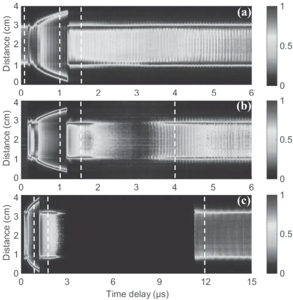
The discharge was photographed from the top view using an ICCD camera to study the discharge temporal evolution on the surface of RF electrode.The exposure time and time interval between two consecutive images are both set to be 10 ns.In each discharge image,the image intensities along the horizontal direction through the center of discharge are selected and then normalized with maximum intensity to obtain the normalized spatial profile of discharge.Figure 4(a)shows the spatial profile of temporal evolution of pulsed discharge and RF discharge.The discharge image at time instant of 0 μs shows that the RF discharge was distributed uniformly above the circular stainless steel electrode before the pulsed discharge was ignited.At 0.2 μs,the rising edge of pulsed discharge produces a ring with a diameter of 2 cm.This plasma expansion is typically found in DBDs due to spreading of accumulated space discharges above the dielectric surface,which are driven by a radial electric field along the dielectric surface induced by the accumulated space charges of positive ions on the surface [17–19].The plasma ring expands outward at a speed of 10 km s−1before the time instant at 1.2 μs of falling edge pulse voltage,when the plasma ring reaches a maximum diameter of 3.8 cm.With the time delay after the pulsed discharge,the residual plasma species concentrated on the ITO surface shrink to the size of stainless steel electrode with a bright ring at the edge of the stainless steel electrode.Figures 4(b)and(c)show the spatiotemporal distributions of discharges with the time interval of 2 μs and 10 μs between the pulsed discharge and RF discharge,respectively.Unlike the pulsed discharges in figure 4(a),from 1.2 μs to 2.8 μs,the highlighted plasma ring at the edge of the stainless steel electrode is weakened.When the time interval between the pulsed discharge and RF discharge is 2 μs,the intensity at the time of RF ignition is mainly concentrated at the plasma ring.As the RF discharge intensity increases,the discharge gradually fills the entire stainless steel electrode area.As the time interval between the pulsed discharge and RF discharge time is 10 μs,the RF discharge uniformly ignited above the stainless steel electrode region.The difference of RF discharge ignition in figures 4(b)and (c) suggests that the spatial distribution and density of residual plasma species from pulsed discharge play important roles on the ignition characteristics of RF discharge.

Figure 4.The spatio-temporal evolution of pulsed discharge and PM RF discharge in the horizontal direction with the time intervals of(a)0 μs,(b) 2 μs and (c) 10 μs.
Figure 5 shows the maximum discharge image intensity at each time instant along the horizontal direction.With the time interval between the pulsed discharge and RF discharge is 0 μs,the intensity of RF discharge with stable operation is 0.7,and the intensities of two pulsed discharge peaks at 0.3 μs and 1.3 μs are 88 and 100,respectively.The RF discharge intensity after pulsed discharge is elevated to be 1.5,which suggests that the pulsed discharge enhances the intensity of RF discharge.With the time interval of 2 μs,as the pulsed discharge is switched off,the discharge intensity decreases to 0.1 at the time instant of 3.2 μs before the ignition of RF discharge.The RF discharge intensity with stable operation can also reach the same magnitude of 1.5 as that with the time interval of 0 μs,which also indicates the assistance of residual plasma species on the RF discharge.With the time interval of 10 μs,the discharge intensity drops below 0.03 and keeps before the ignition of RF discharge,and the RF discharge intensity with stable operation is 0.7,which is same as that before the pulsed discharge.It is suggested that with the time interval of 10 μs between the pulsed discharge and RF discharge,the RF discharge is independent on the pulsed discharge,which proposes that the plasma species produced by the pulsed discharge are exhausted before the ignition of the RF discharge.
Figure 6 shows the discharge intensity distribution in horizontal direction at different time instants.The abscissa 1–3 cm is the position of stainless steel electrode.As shown in figure 6(a),at the time instant of 0 μs,the RF discharge intensity is uniform in the stainless steel electrode region.At the time instant of 1 μs,it shows the residual plasma species distribution of pulsed discharge at pulse rising edge,in which,the two peaks at 0.4 cm and 3.6 cm correspond to the plasma ring formed by the residual plasma species,and the diameter of plasma ring can be estimated to be 3.2 cm,which is larger than that of the stainless steel electrode.At the time instant of 1.5 μs with the pulsed discharge during falling edge of pulse voltage,the edge of plasma ring locates at 0.2 cm and 3.8 cm,respectively,and the image intensity of plasma ring decreases.It also indicates that two highlight plasma rings formed at the boundary of 1.0 cm and 3.0 cm,which are the edges of stainless steel electrode.The spatial distribution of pulsed discharge intensity is in the same range of magnitude in figures 6(b)and(c).At the time instant of 4 μs in figure 6(b),the RF discharge intensities are 12 and 2 at the electrode edge and in the center regime,respectively.At the time instant of 12 μs in figure 6(c),the RF discharge intensity is 1.5,which is similar to that of with time interval of 0 μs in figure 6(a).It is also suggested that the residual plasma species generated by the pulsed discharge accumulate at the edge of the stainless steel electrode,and the ignition of RF discharge is dependent on the time interval between the pulsed discharge and RF discharge.

Figure 6.Discharge intensity distribution at different time instants in the horizontal direction (corresponding to the dotted lines indicated in figure 4).

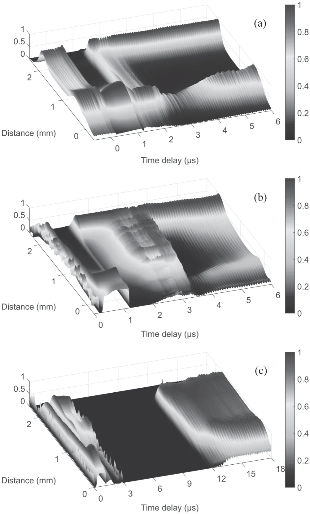
Figure 7.The spatio-temporal evolution of pulsed discharge and PM RF discharge in the vertical direction.The time intervals between pulsed discharge and RF discharge are (a) 0 μs,(b) 2 μs,and(c) 10 μs.
The temporal evolution of cascade discharge spatial profile from side view is shown in figure 7.The exposure time and time interval between the two successive images were set to be 10 ns,the intensity was accumulated along the electrode surface and then normalized to its instantaneous maximum at each time instant to obtain the normalized spatial profile of discharge.The positions of 0 mm and 2 mm are ITO glass and stainless steel electrode,respectively.As shown in figure 7(a),as the pulse voltage is applied to the stainless steel electrode at the time instant of 0.2 μs,the residual plasma species in the discharge gap instantaneously move towards the ITO electrode.After the pulsed discharge and in the phase of RF discharge,the spatial profile of double-hump structure becomes dominated.It is worth noting that the discharge intensity above the glass plate is weaker than that above stainless steel electrode within 3–5 μs,which can be attributed to the sheath formed by the pulsed discharge at falling edge of pulse voltage locates on the stainless steel electrode surface.With the normalization of image intensity,the relative image intensity at the glass plate is reduced.The pulsed discharge is also clearly shown in figures 7(b) and (c).In figure 7(b),at time instant of 1.2 μs,the pulsed discharge at the falling edge of pulse voltage generates the plasma species localized in the regime above the stainless steel electrode surface,which is also demonstrated by the bright plasma ring generated above the stainless steel electrode surface in figures 4 and 6.As the RF voltage is applied at time instant of 3.2 μs,RF discharge is ignited with the assistance of residual plasma species generated in pulsed discharges and forms the double-hump spatial profile in the interelectrode discharge gap.As the unsymmetrical spatial distribution of residual plasma species from the pulsed discharge,the RF ignition is stronger above the stainless steel electrode than that above the ITO glass electrode,which also suggests the assistance of residual plasma species on RF discharge ignition.In figure 7(c),the RF discharge ignites at the time instant of 11.2 μs,which locates in the middle of discharge gap without the assistance of residual plasma species from pulsed discharge [12].At the time instant of 15 μs,the typical spatial profile of double-hump structure in stale operation of RF discharge is formed.

Figure 8.Image intensity of pulsed discharge and PM RF discharge in vertical direction.
Figure 8 is the intensity of discharge image obtained in the side view,which is obtained by accumulating the intensity of discharge image along the electrode surface and normalized by the instantaneous maximum image intensity at each time instant.With the time interval between the pulsed discharge and RF discharge of 0 μs,the RF discharge intensity before the pulsed discharge is 0.3,and the pulsed discharge intensities are 90 and 100,respectively.After the pulsed discharge,the RF discharge intensity is elevated to be 1.0,which demonstrates the assistance of pulsed discharge on RF discharge,as also shown in figure 5.With the time interval of 2 μs,after the pulsed discharge,the image intensity reduces to 0.01 before the RF discharge ignition at 3.2 μs.The RF discharge image intensity reaches 1.0 in the stable operation.With the time interval of 10 μs,the image intensity of pulsed discharge reduces to 0.003,which is one order of magnitude lower than that with time interval of 2 μs and can be considered that the residual plasma species are exhausted.At the time instant of 11.2 μs,the RF discharge is ignited and the discharge image intensity increases to 0.3,which is the same magnitude before the pulsed discharge.The temporal evolution of discharge image intensity from the side view is consistent with that from the top view in figure 5.
4.Conclusions
In summary,the cascade discharge with pulsed discharge and RF discharge was experimentally investigated with a transparent electrode of ITO glass and the temporal evolution of discharge was studied from both horizontal and vertical directions.It is found that the pulsed discharge at the falling edge of the pulse voltage generates the plasma species localized in the regime above the stainless steel electrode,which induces the unsymmetrical spatial profile of RF discharge in the discharge gap.The discharge profiles along the electrode surface and discharge gap of the successive RF discharge are dependent on the time interval between the pulsed discharge and RF discharge.It is proposed that the residual plasma species from the pulsed discharge can assist the ignition of RF discharge to achieve the stable operation of discharge.
Acknowledgments
This work was funded by National Natural Science Foundation of China (Nos.11875104 and 11475043)and open fund of Shanghai center for high performance fibers and composites (X12811901/012).
猜你喜欢
杂志排行
Plasma Science and Technology的其它文章
- DBD coupled with MnOx/γ-Al2O3 catalysts for the degradation of chlorobenzene
- Investigation on pulsed discharge mode in SF6-C2H6 mixtures
- How bead shapes affect the plasma streamer characteristics in packed-bed dielectric barrier discharges:a kinetic modeling study
- Comparative analysis of the arc characteristics inside the convergingdiverging and cylindrical plasma torches
- 1,2,4-trichlorobenzene decomposition using non-thermal plasma technology
- Continuous compositional spread investigation of SiC-based thin films prepared by MW-ECR plasma enhanced magnetron co-sputtering
