Design and analysis of a truss deployable antenna mechanism based on a 3UU-3URU unit
2020-01-09YundouXUJinweiGUOLuyoGUOWenlnLIUJintoYAOYongshengZHAO
Yundou XU, Jinwei GUO, Luyo GUO, Wenln LIU, Jinto YAO,Yongsheng ZHAO,*
a Parallel Robot and Mechatronic System Laboratory of Hebei Province, Yanshan University, Qinhuangdao 066004, China
b Key Laboratory of Advanced Forging & Stamping Technology and Science of Ministry of National Education, Yanshan University, Qinhuangdao 066004, China
c College of Energy and Power Engineering, Lanzhou University of Technology, Lanzhou 730050, China
Abstract Space deployable structures with large calibers, high accuracy, and large folding ratios are indispensable equipment in the aerospace field.Given that the single-DOF 3RR-3RRR deployable unit cannot be fully folded,this study proposes a 3UU-3URU deployable unit with two kinds of DOF:folding movement and orientation adjustment.First,based on the G-K formula,the DOF of the 3UU-3URU unit is analyzed. Then, the 3UU-3URU unit is used to construct a deployable truss antenna with a curved surface,and the DOF of the whole deployable antenna containing multiple 3UU-3URU units is calculated.The structural design of a deployable antenna with two loops is carried out with specific parameters and geometric relations. Next, a DOF simulation of a basic combination unit composed of three 3UU-3URU units is performed. Finally, a prototype of the basic combination unit is manufactured,and the DOF of the mechanism is experimentally verified.©2019 Chinese Society of Aeronautics and Astronautics.Production and hosting by Elsevier Ltd.This is an open access article under the CC BY-NC-ND license(http://creativecommons.org/licenses/by-nc-nd/4.0/).
KEYWORDS Basic combination unit;Degree of freedom (DOF);Deployable truss antenna;Simulation analysis;Structural design
1. Introduction
At present, space deployable mechanisms are widely used in satellite communications, deep space exploration, and space station construction. Due to the limited space in launch vehicles,it is necessary to fold deployable mechanisms during storage and transportation; they are fully deployed when installed.1,2Accordingly, finding new types of deployable mechanisms with high accuracy and large folding rates is the goal of researchers in the aerospace field.
Most deployable antennas are composed of several basic units sharing a connection mode. A variety of deployable unit mechanisms have been proposed both at home and abroad,and the characteristics of unit mechanisms and their application in large deployable antennas have been studied.Lu et al.3constructed a planar deployable antenna mechanism using a Hoekens unit with linear output. Yang and Ding4proposed a new type of hexahedral mechanism based on the spatial polyhedral centripetal mechanism, which can be combined into large planar deployable mechanisms and extensional arms. A new three prism deployable mechanism was also developed by Ding et al.5, which has potential applications in the field of aviation.Vu et al.6put forward a kind of spatial deployable unit structure. Moreover, a unit mechanism with a spacediagonal structure was proposed by Takamatsu and Onoda7to construct a large planar deployable antenna.Xu and Guan8put forward a truss deployable antenna mechanism composed of tetrahedral deployable units. Three studies9-11considered the applications of Bennett,Bricard and Myard linkage mechanisms in deployable mechanisms, respectively. Wang et al.12and Warnaar and Chew13proposed a two-step method for topology analysis and a graph theory, respectively, to design a variety of deployable structures of pyramidal units. Chu et al.14and Wang et al.15both proposed a new type of planar deployable unit structure that could be applied to large deployable antennas. In addition, Cherniavsky et al.16constructed a flat-panel deployable antenna mechanism using a polygon scaling mechanism. Li17studied the kinematics, dynamics, and control methods of deployable ring antennas. Xu18successfully developed the double ring truss deployable antenna,completed the analysis of its networking form and deployment movement, structural design and optimization, dynamics,and thermal characteristics, and then verified the design by building a principle prototype. Shi et al.19comprehensively researched deployable mechanisms, and progress in the development of mechanisms for large deployable antennas has been made in areas such as innovative design, deployment dynamics, and ground unloading experimental methods.
Although a variety of deployable units have been proposed,relatively few mechanisms have been developed for space truss deployable antennas. The tetrahedral deployable units are the most widely used units in space deployable antennas, but the tetrahedral deployable units with only revolute joints8,20and special materials joints (such as shape memory polymeric materials)21rely on joint clearance or elastic deformation of the links to reach the ideal folding state.The ideal folding state refers to the state in which all the parts in the truss deployable antenna reflector and the back frame are close to each other.In this study, a spatial deployable unit 3UU-3URU (R and U representing revolute and universal joints, respectively) is proposed and applied to a tetrahedral truss deployable antenna,to overcome the constraints imposed on the original mechanism due to the limitations of joint clearance and elastic deformation.
The spatial deployable unit is rather complicated, and its DOF analysis, dynamics and structural design are difficult.At present, there are few analyses of such mechanisms in the literature, and no systematic research method has been developed. Therefore, this study examines the basic 3UU-3URU deployable unit and its application to deployable antennas.Building on previous studies,Section 2 points out the problems of deployable antennas composed of single-DOF 3RR-3RRR units and proposes solutions. In Section 3, the 3UU-3URU basic deployable unit is proposed,and its structural characteristics and DOF are analyzed. The basic combination unit is composed of three basic units. This section analyzes the three different modes of combining large deployable mechanisms using the basic combination unit and the rule about the DOF of the deployable antennas. Section 4 introduces the structural design and simulation analysis of the deployable antenna based on the 3UU-3URU unit mechanism. Section 5 describes the experimental investigation performed to verify the theoretical analysis. Finally, the conclusions are presented in Section 6.
2.Problems with truss antenna based on 3RR-3RRR deployable units
A truss antenna based on 3RR-3RRR deployable units consists of several 3RR-3RRR tetrahedron basic deployable units arranged according to a certain networking principle. The schematic of the 3RR-3RRR unit mechanism is shown in Fig. 1. According to Ref.20, the for a 3RR-3RRR tetrahedral deployable unit mechanism shown in Fig. 1 has only one DOF.If the upper node L is fixed and any one of the R joints is selected as the actuated joint, the lower nodes, A, B, and C,are close to or away from the normal,P1P2,of the tetrahedral unit under the effect of the actuation. As the unit moves, the three lower nodes only move and the orientation remains unchanged. A small curved deployable antenna composed of three 3RR-3RRR tetrahedral deployable units, denoted as①, ②, and ③, is shown in Fig. 2. In the state of complete unfolding, the nodes A, B, C, D, E, F, and G in the reflection face are located on a same surface,and the nodes L,M,and N on the supporting surface are located on the another surface.To increase the stiffness of the overall structure and consider the symmetry of the structure, the SRS (S representing spherical joint) chains are added between two adjacent nodes on the supporting surface.The SRS chain is the unconstrained chain, so it will not affect the DOF of the whole mechanism.
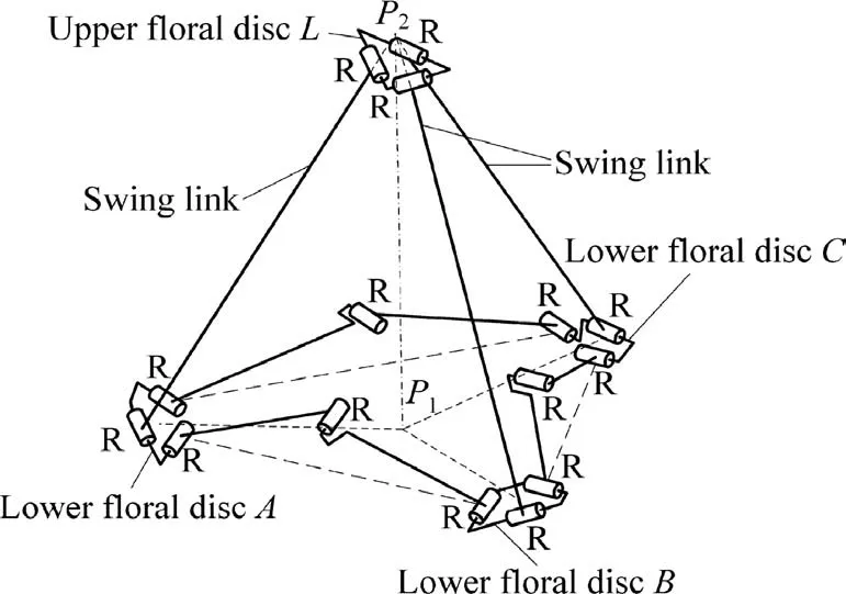
Fig.1 Schematic of 3RR-3RRR deployable unit mechanism.
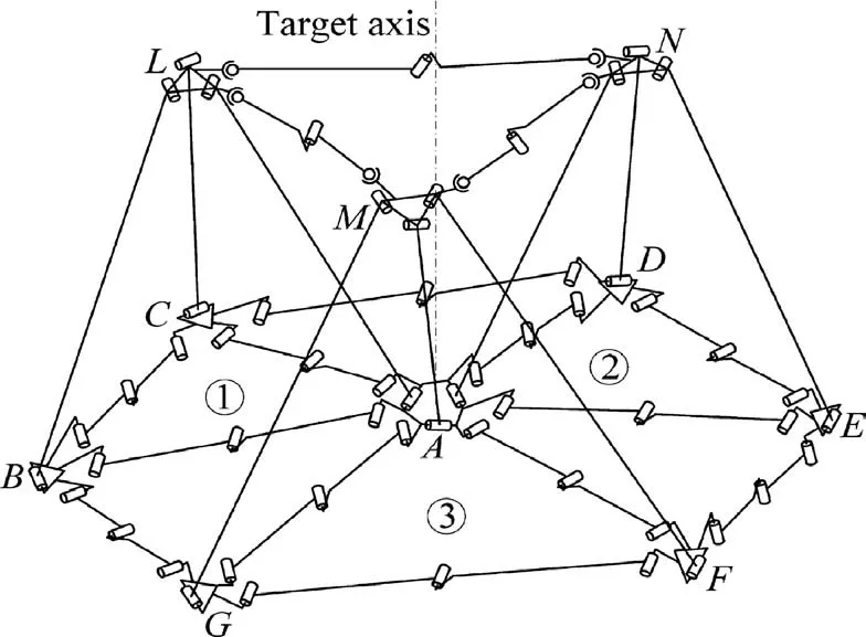
Fig.2 Deployable antenna mechanism composed of three 3RR-3RRR units with a spherical surface.
As the reflector of the antenna is usually a spherical surface or a paraboloid,the bottom faces of the individual tetrahedral units that make up the deployable antenna are not located on a same plane (see Fig. 3), and thus the orientation of the nodes must be different. The R0and r0represent the radius of the envelope loop of the nodes on the reflection surface and the supporting surface respectively,the h0represents the maximum distance between the supporting and reflection surfaces.Moreover,the orientation of the nodes remains the same during the folding process. Thus, the orientations of the nodes are different,and the swing links and nodes on the back surface are not completely folded, as shown in Fig. 4, seriously affecting the folding rate.The Ruand rurepresent the radius of the envelope loop of the nodes on the reflection surface and the supporting surface respectively, the hurepresents the maximum distance between the supporting and reflection surfaces. Therefore, it is necessary to improve the structure of the previous single-DOF tetrahedral unit to realize the same orientations of all the nodes in the folding state. As for a planar reflector, the faces of the units that make up the deployable antenna are located on a same plane during folding or unfolding. A comparison of the planar mechanism and curved surface mechanism shows that their essential difference lies in the influence of the node orientations.

Fig.3 Unfolding state of a deployable antenna mechanism based on a 3RR-3RRR unit.

Fig.4 Folding state of a deployable antenna mechanism based on a 3RR-3RRR unit.
Therefore, if the DOF of the orientation adjustment of the nodes is increased, the inverted tetrahedral unit, LMN-A, can continue to be folded when the nodes move to extreme positions. Then, the orientation of the nodes on the reflection surface will also change so that all the nodes are oriented along the same plane. Thus, the problem of not being able to completely fold a deployable mechanism with a curved surface can be solved.
3.Truss antenna mechanism based on a 3UU-3URU deployable unit
To overcome the above problems,a novel deployable antenna mechanism based on 3UU-3URU is proposed, which can achieve both folding movement and orientation adjustment.
3.1. DOF analysis of a 3UU-3URU deployable unit
A 3UU-3URU deployable unit consists of an upper node,three lower nodes,three swing links,six connecting links,three revolute joints (R), and 12 universal joints (U), as shown in Fig. 5. In the figure, the U joints are represented by two R joints whose axes intersect.The lengths of the three swing links are equal, their upper ends are connected with the upper node P by the universal joints,U1,U3,and U5,respectively,and the axes of U1,U3,and U5near the upper node are coplanar.The lower end of swing link 1 is connected to the lower node A by the U2joint; node A is connected to the connecting links 11 and 32 by the U11and U32joints, respectively. The lower end of swing link 2 is connected to the lower node B by the U4joint; node B is connected to the connecting links 12 and 21 by the U12and U21joints, respectively. The lower end of swing link 3 is connected to the lower node C by the U6joint;node C is connected to the connecting links 31 and 22 by the U31and U22joints, respectively. The lengths of connecting links 11 and 12 connected by the R1joint are equal;the lengths of connecting links 21 and 22 connected by the R2joint are equal;and the lengths of connecting links 31 and 32 connected by the R3joint are also equal.

Fig.5 Schematic of the 3UU-3URU deployable unit mechanism.
The axes of the three swing links intersect at a point,denoted as H, and the lower ends of the swing links intersect with the center points of the three lower nodes, A, B, and C,respectively. Point O is the circumcenter of the triangle ABC.Then, the three axes of the U1, U3, and U5joints near the upper node are perpendicular to the planes AOH, BOH, and COH, respectively, and the other axes of these three U joints are perpendicular to the corresponding swing links and the previous axes, respectively. The axes of the joints U2, U4and U6near the lower node are parallel to those of the joints U1,U3and U5near the upper node, respectively, while the other axes of these three U joints U2, U4and U6are along the axes of the corresponding swing links. The axes of R1, R2and R3are perpendicular to those of the connecting links 11 and 12,the connecting links 21 and 22, and the connecting links 31 and 32, respectively. The axis of the Uijjoint (i=1, 2, 3,j=1, 2) near the connecting link is along the axis of the corresponding connecting link, and the another axis is parallel to the axis of the Rijoint. Without loss of generality, the axes of the R1, R2, and R3joints are not parallel to the plane ABC.
The difference between 3UU-3URU and 3RR-3RRR lies in the increased joints.As described in Section 2,the 3RR-3RRR mechanism has only one DOF and cannot realize the orientation adjustment, so joints are added to reduce several constraints by means of the reciprocal screw theory. Thus, the 3UU-3URU unit mechanism is proposed for this study.
As the three R joints whose axes intersect at a point can be equivalent to a spherical joint(S),the axes of Ui1and Ui2near the connecting links and Rican be replaced by an S joint,based on the geometrical relations of the axes of the 3UU-3URU deployable unit mechanism. One axis of the U joint connecting the swing link and the lower node and the U joint connected to the upper node can also be replaced by an S joint;then, the 3RS-3RSR mechanism, equivalent to that of the 3UU-3URU, is obtained, as shown in Fig. 6.
There are no common or virtual constraints on the 3UU-3URU deployable unit mechanism.According to the G-K formula, the DOF of the 3UU-3URU unit can be obtained as where n represents the number of components including the base and uq(q=1, 2, ..., 15) represents the number of constraints introduced by the qth joint.

Eq. (1) shows that the 3UU-3URU unit has nine DOFs;that is, when the upper node is fixed, nodes A, B, and C can translate to the center O independently and maintain their respective rotational DOFs.Thus,they can also realize the orientation adjustment.

Fig.6 3RS-3RSR mechanism equivalent to that of 3UU-3URU mechanism.
3.2. Basic combination units and their assembly mode
Three 3UU-3URU basic deployable units can be assembled into a basic combination unit mechanism, as shown in Fig. 7. These units share a central node and are connected to each other through URU chains. The three upper nodes of the basic units are also connected by URU chains.The surface on which all the lower nodes are located is the reflection surface, whereas the surface on which all the upper nodes are located is the supporting surface.According to the DOF analysis of parallel mechanisms,22-24each URU chain provides a constraint force that restricts the independence of the two translational DOFs of the two adjacent nodes, and the six URU chains restrict six DOFs of the basic combination unit.As a result, the DOFs of the basic combination unit are 3×9-6=21.
A large deployable antenna mechanism with any aperture can be regarded as a group of connected basic combination unit mechanisms. When two basic combination units are connected by URU chains, as shown in Fig. 8, the URU chain introduces a constraint force. Therefore, the DOFs of the mechanism shown in Fig. 8 are 21×2-2=40.
When two basic combination units are connected by a tetrahedron, it is necessary to consider the consistency of the mechanism of basic units.In this study,the 3UU-3URU tetrahedron is selected, as shown in Fig. 9. In addition to the constraint force introduced by the URU chain,an upper node and three UU chains (including three swing links and six U joints)are introduced by the connection. The number of constraints introduced by the upper node and UU chains is 3×2-6=0. In other words, this connection mode is equivalent to the connection mode shown in Fig. 8. Therefore, the DOFs of the mechanism shown in Fig. 9 are also 40.

Fig.7 Basic combination unit mechanism composed of three 3UU-3URU unit mechanisms.

Fig.8 Connections between basic combination units by URU chains.
When three basic combination units are connected through the second mode, shown in Fig. 9, a closed loop is formed, as shown in the blank middle area in Fig. 10. The closed loop is equivalent to the situation in which the end effector of a serial chain is fixed on the base, and no components or kinematic joints are introduced into the closed loop mechanism formed by this connection mode. Therefore, the mechanism loses six DOFs by introducing the closed loop. Additionally, the nodes on the supporting and reflection surfaces are connected by URU chains, so 15 and 3 URU chains are added to the supporting and reflection chains, respectively. Consequently, the DOFs of the mechanism shown in Fig. 10 are 21×3-6-1×(3+15)=39.
According to the above analysis of the three connection modes, a deployable antenna mechanism can be formed by any number of basic combination units,and the corresponding DOFs can also be obtained. The first two connection modes have the same number of DOFs, but many more components are used in the second mode. The overall stiffness of the first two modes is lower than that of the third mode.The third connection mode has relatively fewer DOFs, and its nodes on the supporting surface are connected. Moreover, three adjacent upper nodes and a lower node can form an inverted 3UU-3URU tetrahedron unit mechanism in the third mode. Therefore,the overall stiffness of the deployable antenna mechanism connected by the third mode is greatly increased.

Fig.9 Connection between basic combination units through a tetrahedral unit.
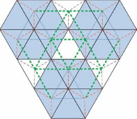
Fig.10 Three basic combination units connected to form a closed loop.
3.3. Law of the DOFs of deployable antenna mechanisms with large apertures
A deployable antenna supporting mechanism containing n (n ≥1)loops can be obtained based on the modes of connection between the basic combination units,as shown in Figs.11-13.The DOFs of the mechanisms shown in Figs.11-13 are calculated by taking the basic combination unit as the basic calculation unit; this makes it possible to obtain the law of the DOFs of the antenna mechanisms with large apertures.

Fig.11 Antenna mechanism containing one loop.

Fig.12 Antenna mechanism containing two loops.
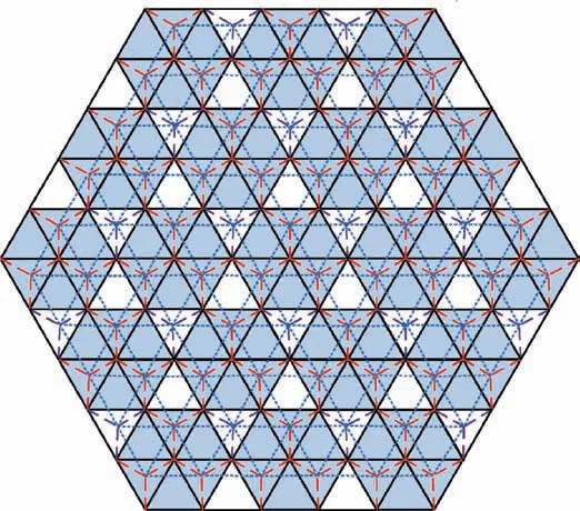
Fig.13 Antenna mechanism containing three loops.

Fig.14 Extra parts of a two-loop antenna mechanism compared with a one-loop antenna mechanism.
Fig. 14 shows the relative number of parts in a one-loop antenna mechanism and a two-loop antenna mechanism. The extra parts in a three-loop antenna mechanism are shown in Fig. 15. Based on the calculations in Section 3.2, there are 21 DOFs in the basic combination unit (one-loop antenna mechanism). From Fig. 14, we can see that compared with a oneloop antenna mechanism, a two-loop antenna mechanism has six more basic combination units (with 21 DOFs for each unit), six additional chains consisting of three swing links and a top node (with no constraints), six boundary URU chains (with each providing a constraint), six closed-loop mechanisms (with each providing six constraints), and 42 URU chains added on the supporting surface.Therefore,compared with a one-loop antenna mechanism, a two-loop antenna mechanism has the following number of extra DOFs:6×21-6×0-6×1-6×6-42×1=42.
Similarly, Fig. 15 shows that compared with a two-loop antenna mechanism, a three-loop antenna mechanism has the following extra parts:12 basic combination units,12 additional chains consisting of three swing links and a top node,12 boundary URU chains, 12 closed-loop mechanisms, six increased URU chains of six basic combination units(with five DOFs for each unit) and 96 URU chains added on the supporting surface.Therefore,compared with a two-loop antenna mechanism,a three-loop antenna mechanism has the following number of extra DOFs:
12×21-12×0-12×1-12×6-6×5-96×1=42
Similarly, the number of extra DOFs in a four-loop antenna mechanism compared with a three-loop antenna mechanism is
18×21-18×0-18×1-18×6-12×5-150×1=42

Fig.15 Extra parts of a three-loop antenna mechanism compared with a two-loop antenna mechanism.

In sum, the number of extra DOFs in an i loop antenna mechanism compared with an i-1 loop antenna mechanism is Therefore,the DOFs of the deployable antenna mechanism composed of the basic combination units shown in Fig. 11 form an arithmetical series; that is, the number of DOFs in an antenna mechanism containing n loops is

4. Structural design and simulation analysis of a truss antenna based on a 3UU-3URU deployable unit
4.1. Structural design
4.1.1.Scale design of a deployable supporting mechanism with a curved surface
There is only a slight difference in size between the 3UU-3URU units constituting the deployable antenna mechanism,and the geometric relationship between the basic combination units remains unchanged.
In this study, the symmetrical paraboloid with an aperture of 4 meters is selected as the reflection surface. It is designed with a focal diameter ratio of 0.5 and a fine fraction of 8.The paraboloid is divided into a series of triangle units; then,the center points of the nodes on the reflection surface are obtained, and the initial length of the synchronous links is obtained by connecting two adjacent nodes, as shown in Fig. 16.
The length of the swing links is set to 600 mm, and the initial length of the synchronous links and the nodes on the back surface can then be obtained, as shown in Fig. 17.
Finally, according to the geometrical constraints of the deployable antenna mechanisms, the axes on the nodes, swing links, and synchronous links are determined.
4.1.2.Scale design of a deployable supporting mechanism with a curved surface
Based on the detailed scale parameters obtained above,the key parts of an antenna mechanism, including the nodes, swing links, synchronous links, and joints, are designed, as shown in Figs. 18-20.
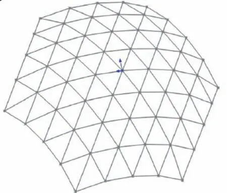
Fig.16 Position of nodes and initial length of synchronous links on reflection surface.

Fig.17 Position of nodes and initial length of synchronous links on back surface.
Fig.21 shows the final design of the three-dimension model of a deployable antenna with a curved surface.
4.2. Simulation analysis
4.2.1. Motion simulation of a basic combination unit
To explain the motion law of the deployable antenna mechanism based on a 3UU-URU unit mechanism,the basic combination unit, i.e., the one-loop antenna mechanism, is used as an example in the simulation analysis. The simulation model of the basic combination unit is established using the Adams software, as shown in Fig. 22. To ensure that the mechanism can realize the determined movement, at least 21 drivers need to be included in the simulation model.
To verify that the novel deployable mechanism can achieve both the folding movement and orientation adjustment,we set the input displacements of the drivers to ensure that the mechanism can reach the folding state. Before moving to the state shown in Fig.4,the folding movement and orientation adjustment occur synchronously. Then, only the orientation adjustment occurs. In the state shown in Fig. 4, the nodes have different orientations and the nodes on the back surface are not folded tightly. We then lock the drivers (motion_7-motion_21) and adjust the input displacements of the drivers(motion_1-motion_6),as shown in Fig.22,to continue to realize the orientation adjustment of the nodes. Eventually, the nodes on the reflection surface and the back surface are all tightly folded and the nodes all have the same orientation.All the links are folded in place, and the smallest overall volume is achieved, as shown in Fig. 23. The Rvand rvrepresent the radius of the envelope loop of the nodes on the reflection surface and the supporting surface respectively, the hvrepresents the maximum distance between the supporting and reflection surfaces.

Fig.19 Structures of swing links.
The ZYX Euler angles are used to describe the orientation of each node relative to the base node A shown in Fig.7 during the movement of the 3UU-3URU basic unit. Take node C as an example. The rotation matrix of the centroid coordinate system attached at node C relative to node A is

where α, β, and γ represent Euler angles.
The rotation matrixACR can also be represented in the following form related to the inputs of the drivers:

where rij(θ )is a function of θ,i,j=1,2,3,θ=θ2-θ1,and θ1,θ2represent the inputs of the rotation about the two axes attached at the swing link CL.
Combining Eqs. (3) and (4), we get


Fig.18 Structures of nodes.

Fig.20 Structures of synchronous links.

Fig.21 Three-dimension model of a deployable antenna with a curved surface.

Fig.22 Simulation model of basic combination unit.
The time-variation curves of α,β,and γ are obtained as shown in Fig. 24.
According to the simulation results, the initial values of α,β, and γ remain unchanged during 0-34.5 s, indicating that the folding process of the mechanism occurs during 0-34.5 s.During this period, node C only moves and its orientation remains unchanged. After 34.5 s, the nonlinear changes in α,β, and γ show that the orientation adjustment of the nodes has started. In the process of orientation adjusting, the swing links continue to swing tightly,and the nodes on the back surface continue to fold. It is further verified that the basic combination unit composed of the 3UU-3URU basic units can achieve the necessary movements for folding and orientation adjustment.

Fig.23 State of complete folding.
4.2.2. Analysis of the folding rate of a basic combination unit

Fig.24 Euler angles of node C relative to node A.
To better illustrate that the deployable mechanism proposed in this study possesses high deployable performance, the folding rate is defined as the ratio of the occupied space in the completely unfolded and folded states. The completely unfolded state of a spherical deployable mechanism composed of three basic 3RR-3RRR units is shown in Fig. 3. The radius of the envelope loop of the nodes is R0=0.5259 m on the reflection surface, and is r0=0.3845 m on the supporting surface, with the maximum distance between the supporting and reflection surfaces being h0=0.5517 m. The last folding state of the spherical deployable mechanism composed of three basic 3RR-3RRR units is shown in Fig. 4. The radius of the envelope loop of the nodes is Ru=0.0717 m on the reflection surface, and is ru=0.1353 m on the supporting surface, with the maximum distance between the supporting surface and the reflection surface being hu=0.6102 m. Thus, the folding rate can be calculated as

where V0and V1denote the volume of the deployable antenna mechanism in the fully unfolded and folded states,respectively.
The volume of the basic combination unit mechanism based on the 3UU-3URU basic unit is still V0in the completely unfolded state. As shown in Fig. 23, in the folded state, the radius of the envelope loop of the nodes is Rv=0.0733 m on the reflection surface,and is rv=0.0564 m on the supporting surface, with the maximum distance between the supporting and reflection surfaces being hv=0.6209 m. Thus, the folding rate can be obtained as

According to the results of the above calculations, the folding rate of the deployable mechanism composed of 3UU-3URU basic units is obviously higher than that of the proposed mechanism composed of 3RR-3RRR basic units,showing that the novel deployable mechanism has good deployable performance.
4.2.3. Motion simulation of multiple basic combination units
A large truss deployable mechanism can be composed of multiple basic combination units.Fig.25 shows such a mechanism composed of seven basic combination units. The basic combination unit A in the center position is the first loop. The surrounding six basic combination units, B-G, are the second loop, and the adjacent basic combination units are connected by URU chains to form closed loops.A large parabolic surface can be constructed on the reflection surface.
According to the above analysis,the basic combination unit mechanism composed of 3UU-3URU basic units can achieve both folding and orientation adjustment movements. When a large deployable mechanism is assembled from seven basic combination units, the folding and orientation adjustment movements can also be realized by adding reasonable drivers,as shown in Figs. 26 and 27. At the end of the folding movement, each node on the reflection surface is folded tightly,and the planes of these nodes form a parabolic surface. At the end of the orientation adjustment movement, the nodes on the reflection surface and the back surface are adjusted to be on a same plane. This further verifies that the 3UU-3URU basic unit and its combination unit can realize not only the movement of folding, but also the independent orientation adjustment, which is expected to be applied to large truss deployable antenna mechanisms with curved surfaces.

Fig.25 Large truss deployable mechanism composed of seven basic combination units.

Fig.26 End of folding movement of a large truss deployable mechanism with seven basic combination units.
5. Presentation of results
Building on the results of the theoretical analyses, this study manufactures and assembles a prototype of a combination unit composed of three 3UU-3URU basic units, as shown in Fig.28.Experiments are carried out to verify if this prototype can achieve the desired folding and orientation adjusting movements.
The basic combination unit has two kinds of DOFs:folding and orientation adjusting. The folding movement can be driven by the torsion springs added at the synchronous joints on the reflection surface,and the orientation adjustment movement can be driven by the torsion springs added at the synchronous joints on the back surface. When the drivers added to the back surface are locked, the final folding state of the nodes on the reflection surface is obtained (Fig. 29), driven by the synchronous joints on the reflection surface.This result verifies the folding movement of the deployable antenna mechanism. When the drivers on the reflection surface are locked,the middle state of the nodes on the back surface is achieved,as shown in Fig. 30, driven by the synchronous joints on the back surface This result verifies the orientation adjustment movement of the deployable antenna mechanism. Further,simultaneously driven by the synchronous joints on the reflection and the back surfaces,the half folding state and complete folding state of the mechanism are obtained, as shown in Figs. 31 and 32, respectively. This result verifies that the deployable antenna mechanism can achieve the movements of both folding and orientation adjustment, thus able to achieve complete folding.

Fig.28 Prototype in fully unfolded state.

Fig.29 Final folding state driven by the synchronous joints on reflection surface.
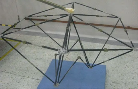
Fig.30 Middle state driven by synchronous joints on back surface.

Fig.27 End of orientation adjusting movement of a large truss deployable mechanism with seven basic combination unit.

Fig.31 Half folded state.
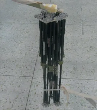
Fig.32 Completely folded state.
6. Conclusions
(1) Given that truss antenna mechanisms formed by 3RR-3RRR tetrahedral deployable units cannot be fully folded, this study proposes a spatial deployable unit mechanism with 3UU-3URU to construct a deployable antenna mechanism with a curved surface. The proposed antenna has two kinds of DOFs, folding movement and orientation adjustment, so the shortcomings of the original mechanism can be overcome.
(2) After the DOF analysis of the 3UU-3URU tetrahedral unit and its basic combination unit, three connection modes for combining the basic combination units into a large antenna mechanism are proposed, and a universal formula for calculating the DOFs of a deployable antenna mechanism with n loops is obtained.
(3) The scale and structures of the key parts of a large truss deployable antenna mechanism based on the 3UU-3URU unit are designed, and simulation models of the basic combination unit and a deployable antenna mechanism composed of seven basic combination units are built.Moreover,a prototype of a basic combination unit is manufactured and assembled. The simulation and experimental results show that the truss deployable antenna mechanism based on the 3UU-3URU unit has two kinds of DOFs, folding movement and orientation adjusting,allowing the antenna to be folded completely.Furthermore, the folding rate is much higher than that of an antenna mechanism composed of 3RR-3RRR units.
Acknowledgements
This study was co-supported by the National Natural Science Foundation of China(No.51675458),the Key Project of Natural Science Foundation of Hebei Province of China (No.E2017203335), and the Youth Top Talent Project of Hebei Province Higher Education of China (No. BJ2017060).
杂志排行
CHINESE JOURNAL OF AERONAUTICS的其它文章
- Fracture behavior and self-sharpening mechanisms of polycrystalline cubic boron nitride in grinding based on cohesive element method
- A CFD-based numerical virtual flight simulator and its application in control law design of a maneuverable missile model
- A formal approach using SysML for capturing functional requirements in avionics domain
- Target-enclosing aきne formation control of two-layer networked spacecraft with collision avoidance
- Measuring the resilience of an airport network
- Distributed intelligent self-organized mission planning of multi-UAV for dynamic targets cooperative search-attack
