A formal approach using SysML for capturing functional requirements in avionics domain
2020-01-09ShofnZHUJinTANGJenMrieGAUTHIERRpheFAUDOU
Shofn ZHU, Jin TANG, Jen-Mrie GAUTHIER, Rphe¨l FAUDOU
a Beijing Aeronautical Science and Technology Research Institute, COMAC, Beijing 102211, China
b Samares-Engineering, Blagnac 31700, France
Abstract In this work, a Model-Based Systems Engineering approach based on SysML is proposed.This approach is used for the capture and the definition of functional requirements in avionics domain. The motivation of this work is triple: guide the capture of functional requirements,validate these functional requirements through functional simulation,and verify efficiently the consistency of these functional requirements.The proposed approach is decomposed into several steps that are detailed to go from conceptual model of avionics domain to a formal functional model that can be simulated in its operating context.To achieve this work,a subset of SysML has been used as an intermediate modelling language to ensure progressive transformation that can be understood and agreed by system stakeholders. Formal concepts are introduced to ensure theoretical consistency of the approach.In addition,transformation rules are defined and the mappings between concepts of ARP4754A civil aircraft guidelines and SysML are formalized through meta-model. The resulting formalization enables engineers to perform functional simulation of the top-level functional architecture extracted from operational scenarios. Finally, the approach has been tested on an industrial avionics system called the Onboard Maintenance System.
KEYWORDS Avionics systems;Conceptual model;Functional simulation;Model-Based Systems Engineering
1. Introduction
In the avionics domain, certification rules and ARP4754A1guidelines require that all engineering artifacts are traced to requirements. This makes capture of requirements a crucial sub process of the overall development process: any missed or misunderstood requirement can lead to wrong system definition and then wrong realization.With pure document-centric engineering approach, wrong or missing requirements may be detected very late in the system development life cycle, sometimes during product validation. Early validation is needed to decrease risk of such situation.In addition,systems become more and more complex with rising number of functions and of technologies to integrate,2which leads to a rising number of requirements to manage and engineer. Verification of individual requirements can still be addressed by humans but not the global consistency of the requirements set as the cross-checking leads to millions of cases.So, it is fundamental to transition to a ‘‘consistent-by-construction” approach.
Model Based Systems Engineering(MBSE)is seen today as a good approach to allow early validation on model and to support building of a consistent set of system requirements.In this article, a SysML3approach is used to support the ARP4754A capture requirements process.The approach relies on two fundamental goals: ensuring a consistent by construction set of functional system requirements using models and giving means to execute those functional system requirements for early validation of the system seen as a black box. To achieve those goals, the proposed approach needs to address three main needs: being formal, enabling automation, and enabling execution for validation. The contributions of this article are threefold. First, a formalization of operational scenarios,functional scenarios and functional chains is proposed.Second, a transformation between operational scenarios and functional chains is defined and implemented. Finally, a mapping between the formal framework, SysML, and the ARP4754A is illustrated and formalized with meta-models.
In this way,the proposed approach permits to capture blackbox operational scenarios using SysML sequence diagrams.Then,the functional scenarios are identified and combined into functional chains modeled by SysML activity diagrams.From the model, functional interface requirements can be identified and captured. Finally, the simulation of top-level functional chains model can be achieved to validate continuously functional chains against operational scenarios. Experiments have been conducted on an industrial case study:the Onboard Maintenance System(OMS)which is an avionics subsystem.
The rest of the paper is organized as follows: existing related work are discussed in Section 2.The capture of requirements process is introduced in Section 3. Section 4 details the proposed approach with formal concepts and meta models to reach consistent and executable functional specification models. Experiments and results are presented and discussed in Section 5.Finally,the conclusion and future work are outlined in Section 6.
2. Related work
Writing requirements in natural language remains the most common approach currently found in industry.For more than 20 years most industrial companies involved in aerospace domain have put strong efforts on the quality of their requirements to reduce errors and ambiguities.After some local initiatives,good practices have been shared between different actors and different domains and today we can find good practices on writing requirements at INCOSE.4Most of those practices can be organized into patterns or boiler plates5,6and can be completed by the support of ontologies7to guide use of words and of their relations according to the domain and associated semantics. When applying those practices, requirements are of better quality.8But those approaches based on constrained or guided natural language are not yet very efficient to address relationships between requirements, i.e. dependencies, induction, and logic, even with support of ontologies. Those approaches do not help much in verification of global consistency.
Through the advent of standard modelling languages like OMG UML/SysML, there have been many attempts to use semi-formal modelling approach to capture functional needs and functional constraints on a system of interest. For instance, IBM Harmony SE,9or SysMOD.10Those approaches provide some interesting results in detection of issues concerning consistency of requirements and missing requirements. But as they rely on semi-formal language with remaining semantic variation points,there can still exist multiple interpretations.
Model-Based Systems Engineering approaches have been proposed for avionics systems.In Refs.11,12the authors present a SysML based approach to ensure consistent allocation between functional layer and software architecture. Interface Control Document (ICD) for ARINC 664 can be generated from the model.In addition,checkers are implemented to verify the consistency of the allocation between functional layer and logical or physical layer. The main difference with our approach concerns the requirements capture not considered in Refs.11,12.
A method to optimize function allocation,and system configuration using constraints and Capella architecture is presented in Ref.13. The method succeeded to perform design space exploration and optimization of a Distributed Integrated Modular Avionics. This method is complementary to the one proposed in this article. Indeed, the synthesis of the highlevel functional architecture from operational scenario is at a higher level compared to the method proposed in Ref.13.Model-based robustness testing for avionics software has been investigated in Ref.14. SysML based safety analysis in presented in Ref.15. It combines MBSE with SysML and modelchecking to ease communication between system engineer and safety engineer.Refs.14,15focus on V&V rather than focusing on how to capture consistently functional requirements while ensuring functional validation using simulation in the context of ARP4754.
Using a formal modelling language permits to remove all possible ambiguities related to different possible interpretations. B modelling language, for instance, has been used with success on RATP Meteor subway line in Paris16and more recently Event-B to build formal requirements refinement using patterns17. The use of Petri Nets to formally verify scenarios and use cases has been proposed in Ref.18.Stimulus tool from Argosim19allows expressing system requirements through a formal model.From that model it becomes possible to launch simulation and leverage the results to identify errors in requirement expression.
This tool is thus considered as an enabler for requirement validation. FORM-L,20designed by EDF Research, aims at better describing requirements in multi-physical models and ease their verification.SDL-RT21is a formal and standardized language to describe the structure and the behavior of communicating systems.
Synthesis of Activity Diagram from Sequence Diagrams are proposed in Ref.22.To that end,the authors identified patterns of Sequence Diagrams and defined rules for mapping them to corresponding parts of Activity Diagram.Finally,the work of Briand et al.23,24propose to generate activity diagrams from use cases. In particular, they propose restriction rules on the use of natural language to formalize the way preconditions,post-conditions, and flow steps are written within use cases.In the present work,sequence diagrams should respect conformance rules derived from systems theory, i.e. causality and data continuity.
3. Requirements capture process
COMAC (Commercial Aircraft Corporation of China)designed an SE process in line with ARP4754A. According to project management process, the avionics system development starts from project feasibility study and project approval,complying with ARP4754A and AIR6110. The avionics system development consists the following five phases:
(1) JCDP(Joint Concept Design Phase)mainly focusing on feasibility study, project approval, sub-system bidding and supplier selection.
(2) JDP (Joint Definition Phase) including system development planning, capture and validate requirements, preliminary design, system airworthiness and test environments definitions.
(3) Development Verification&Manufacture Phase,including system critical design phase, manufacture for development phase, lab verification phase.
(4) Certification Phase, including ground onboard test phase, flight test phase.
(5) Post-certification Phase.
The contributions of this article fit into the JDP,when capture and validation of requirements is performed. The Fig. 1 outlines the inputs and the outputs of the requirements capture activity.Capturing requirement starts by taking onto consideration the results of JCDP, i.e. customer requirements, reuse requirements, aircraft level requirements, and allocated aircraft level functions to the corresponding avionics systems.In addition, results of Functional Hazard Analysis (FHA)and Preliminary Aircraft Safety Assessment (PASA) are considered all along the requirements capture activity. The goal of this activity is to obtain a preliminary set of high-level System Requirements Specification(SRS)for System Requirements Review (SRR). In this article, non-functional requirements such as safety or performance are parts of further work.
4. Using SysML to guide requirements capture
In this section a set of concepts for capturing requirements in a progressive and iterative approach are defined. Fig. 2 depicts the proposed iterative approach.The first step consists in capturing functional needs using a semi-formal model, with some flexibility in the expression so that it does not require too much knowledge on notation. Focus is put on the structuring of needs using SysML Use Cases (UC). It is discussed in Section 4.1.
In a second step, a guided dialog to solve remaining ambiguities is performed: this step is called ‘‘semantics clarification”. It permits to progressively raise the level of formalism of the operational scenarios. This step is discussed in Section 4.2.
The formalized scenarios are then combined to produce executable top-level functional behavioral model thanks to the use of transformation rules.The resulting model conforms to Foundational subset for executable UML(FUML),25a formal subset of UML that provides execution semantics. Concurrently, we use each scenario to produce a simple behavioral model for each system actor (human operator or external system in interaction with considered system). Those models are used to trigger events to the system model as expressed in the operational scenarios.The top-level functional behavior of the system can then be automatically simulated in its functional operating context for each black box operational scenario.It provides a convenient means to support the validation of the system functional interfaces. Note that scenarios are also used to identify modes of operations, but this is beyond scope of this article. The approach ensures that final model is traced to initial functional requirements or assumptions made in case it was not possible to get customer feedback. It conforms to ARP4754A recommendations on traceability and provides support for impact analysis in case of any change in the input functional requirements. The progressive definition of functional chains and their simulation are discussed in Section 4.3.

Fig.1 Capture requirements process overview.

Fig.2 Flowchart of proposed approach.
In the rest of this section,formal definitions of key concepts are proposed. First let us define the basis of the framework with a formal definition of a System from Ref.26. This system definitions is a refinement of the formal definition of a System initially proposed by Wymore.27A System of Interest(SoI)is a 7-tuple defined by:

where Tsis a time scale called the time scale of the system,Input= {In, I}and Output= {Out, O}are input and output datasets, S is a non-empty ε-alphabet, called the ε-alphabet of states,q0is an element of S called the initial state,F is a function called functional behavior such that:

and Q is a function called states behavior such that:

An ε-alphabet is defined by Ref.26to be a set of data (any element that can be exchanged between any real systems)containing the universal blank symbol ε. In addition, a dataset is defined to be a pair D ={D, B}, where D is an ε-alphabet,and B is a pair {read, write} that enables to implement data behavior (persistent, consumable, accumulative).
In the proposed formal framework, ∑is assumed to be a causal system, i.e. that requires a semantic notion of time to respect an intuitive notion of causality28:if one event A causes another event B, then every observer should see A occurring before B. Finally, we consider ∑to be an open system in the sense of Von Bertalanffy,29i.e. a system that interacts with its environment. Interactions can be energy, matter, or information transferred to or from the system boundary.In the rest of the article,the symbol Γ is used to denote a set of elements,and ε for the empty element.
4.1. Structuring needs with use cases in avionic context
In the context of civil aircraft engineering, the use of ARP4754A is strongly recommended. ARP4754A suggests identifying aircraft and system-level functions for the development of the aircraft or a system of the aircraft.
The first step of the proposed approach for requirements capture is to structure the needs extracted from customer and aircraft level requirements input documents. In the proposed approach, SysML use cases support such structuring activity. In Ref.30the authors give practices concerning effective use case identification and modelling. At first, by definition, a use case should bring value for at least one system stakeholder. For instance, one of the aircraft flight recorder main functional values is to register the recent history of the flight so that it can be made available to the National Transportation Safety Board in case of accident. Next, a use case should be autonomous in its execution, meaning that it can be executed without the need of another use case except included use case. Finally, a use case should also be complete,meaning that,at the end of the UC execution,the system is in a stable or error state.
Raw use cases are first defined from the aircraft functions allocated to the system. Those raw use cases are analyzed and checked to ensure that they respect rules including functional value for at least one stakeholder, autonomy and completeness as mentioned previously. Next, roles played by end users and external systems are identified and formalized as actors from all input stakeholders’ documents (including customer’s). SysML refine relationship is used to create links between use cases and aircraft level requirements allocated to the system under study.Those traceability links can be defined and maintained in a Use Case Diagram or using a traceability matrix.
4.2. Capturing black-box operational scenarios
After structuring functional needs within use cases, the expected behavior of the system is captured for each use case using black-box operational scenarios. As shown on Fig. 3,the black-box operational scenarios are defined as SysML interactions owned by UC (owned behaviors). Those interactions are represented graphically by Sequence Diagrams. For each use case,the focus is put on functional messages between system and use case’s associated actors. The first message shows the triggering event of the scenario. The expected responses of system to an input event can be described with reflexive messages attached to the Sequence Diagram lifeline representing the System of Interest. The capture of those reflexive messages is useful to provide a first list of top-level functions,but it is not main priority at that stage because that list is likely to change when other requirements are considered.Focus is rather put on functional interfaces, i.e. the incoming and outgoing functional messages, and on the causal dependencies between those functional messages. The goal is to deduce consistent functional scenarios that cross the system of interest and interact with its functional operating context represented by actors.
The following defines the formal concepts used in this conceptual model. In addition, constraints on types and causality are formally defined.
A black-box operational scenario is composed of one or more functional scenarios. A black-box operational scenario shall contain lifelines that represent either the System of Interest or an Actor.Let βsthe black-box operational scenario to be a 3-tuple defined by:

where ΓLis the set of lifelines, Γφis the set of functional scenarios, and ftis a lifeline typing function defined by:

In the proposed framework,a functional scenario φ ∈Γφis a causal consistent sequence of functional messages that starts by an incoming message (external request), followed by the system expected behavior as response to that request. The expected behavior is represented by a SysML execution specification (thin green rectangle on the lifelines). Let φ a functional scenario on a System ∑to be the 3-tuple defined by:
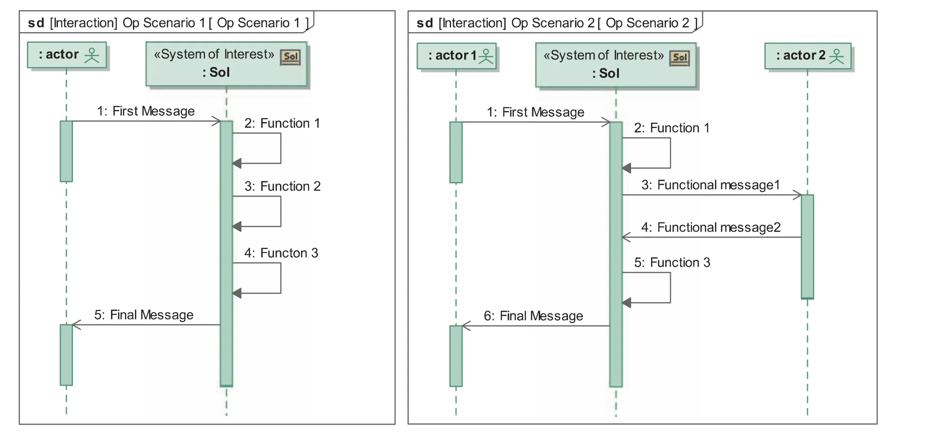
Fig.3 Black-box operational scenario examples with only one functional scenario.

where μ0is a triggering incoming functional message, Γμis a set of functional messages, and✧is a function called occurs at that associates a message to a time instant:

A functional message is emitted by a source lifeline and received by a target lifeline. In the proposed framework, three kind of message are defined:incoming,outgoing and reflexive.Incoming and outgoing messages carry functional data (data,material or energy) while reflexive messages specify internal functions. Let μin,μout∈Γμto be a functional incoming and outgoing message defined by the 3-tuple:

where,source and target are respectively the source and target lifelines in ΓL,and data is a dataset. Reflexive functional message can now be defined. Let μra functional message defined by the 3-tuple:

A functional scenario shall be causal consistent for each functional message.The causal dependency between two functional messages means that it always exists a causal relationship between these two messages. Therefore, reflexive and outgoing messages shall be considered as being consequences of new external events (incoming messages) or internal events(reflexive messages). Indeed,the System does not take any initiative by itself: if μ is a reflexive message or an outgoing message, then it has sense and exists because of a previous cause,e.g. a request from an actor. In addition, each outgoing message has sense and exists because of an internal cause, i.e.the system reaction.
These causality properties are directly derived from the causality property stated in the general system theory29:a system’s output is a consequence of given system’s inputs and internal state change.
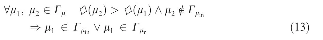
Let φ be a functional scenario, μ0be an incoming message occurring at time t0and that triggers a new execution, Γμinthe set of incoming messages, Γμoutthe set of outgoing messages,and Γμrthe set of reflexive messages,then φ is said causal consistent if and only if:
The meta model of the Fig. 4 shows the link between the previously defined formal concepts, SysML concepts, and the ARP4754A concepts.The data carried by functional incoming and outgoing messages are mapped to SysML signal concept since signals can be used to specify communication between systems and flow properties such as data, material or energy.Shortcut relations are used for simplification purpose: real associations can be found in the SysML specifications.
4.3. Definition of executable functional chains
The goal of this step is to combine all the functional scenarios that start with the same incoming message to define executable functional chains.As depicted by the Fig.5,SysML activity concept is used to formalize a set of functional chains and Activity Diagram(AD)to represent it.This last is a directed graph G={V,E},31where V is set of vertices and E is a set of edges.The vertices V are SysML actions and edges E of the graph are SysML control or object flows. SysML actions can be Call Behavior Action (call to Function 1), Accept Event Action(First Message),and Send Signal Action(Final Message).This activity is executable by any fUML animation engine.
A functional chain connects the system functional interfaces to system function calls. Therefore, a functional chain consumes system’s inputs to produce system’s outputs through the activation of nested function calls.Let ξ,a functional chain to be a 4-tuple defined by:
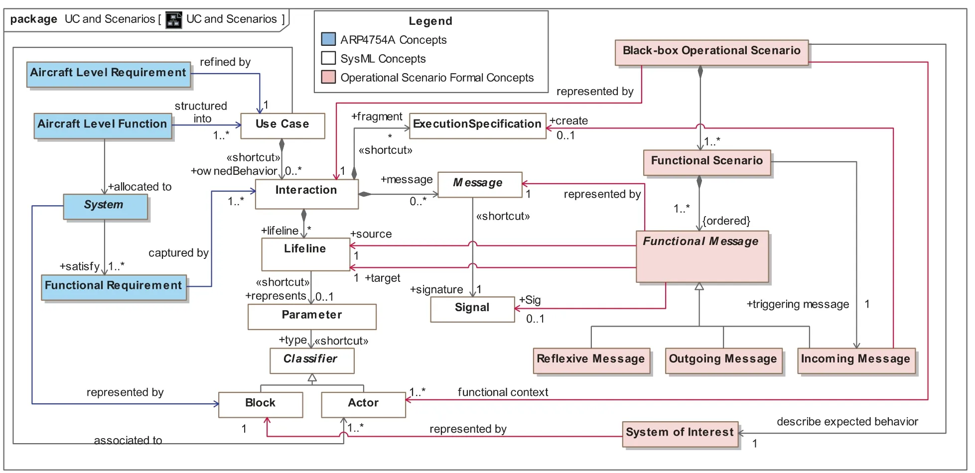
Fig.4 Meta model for black-box operational scenarios.
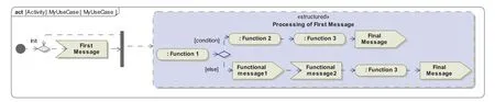
Fig.5 Example of executable top-level functional chains.

where Input and Output are datasets(see Definition(1)),G is a nested graph of function calls, and fpsis a function called system functional execution such that:

There is no strict consensus on ‘‘function” definition between the considered domains: the ARP4754A gives its own definition,while the INCOSE Systems Engineering Hand-Book and INCOSE SEBoK glossary32propose slightly different definitions. In the proposed framework, a system function is defined to be the intended behavior of a system that consumes functional flows and produces functional flows regardless of implementation.
This definition is a combination of the definitions given by the ARP4754A and the SE HandBook. The concepts of function definition and function call are separated.This separation is motivated by the need of reusable functions.In that way the same function can be called in several architectures, or several models.With that separation,the behavior of a given function definition can be expressed by a nested directed graph G of nodes V representing lower-level functions calls.
Let ψ, a function definition to be a 5-tuple defined by:

where ψinand ψoutare function input and output datasets,G={V,E}is a nested graph where V is a set of function calls and E is a set of functional flows,fpis a functional called function data production such that:

and fψis a function called function definition instantiation that associates a typing function call to its definition:

The meta model of the Fig. 6 summarizes the link between the previously defined formal concepts, SysML and the ARP4754A. Within the framework, accept event actions and the send signal actions are also linked to signal. Therefore,the signal concept become a shared concept between operational scenario and functional chains. Consequently, signals combine the different datasets usage (scenario) into a single definition that can be used later during functional chains extraction and refinement.
4.4. Transformation rules

Fig.6 Meta model for Functional Chain.
The transformation step consists in combining functional scenarios to obtain a single definition of the top-level functional architecture that conforms to those scenarios. In addition,the same rules are applied to extract the simulation context and executable abstract test cases from the operational scenarios. To illustrate the combining approach, let’s take the two scenarios of the Fig.3.First,from the reception of a message,a new execution specification is created. Then, a new functional chain is created, through its processing with internal functions, and potentially sending and receptions of message to and from other actors. In our example, the second operational scenario starts with the same incoming message than in the first scenario. In that case, their respective execution logic is combined by adding SysML decision node. The Fig. 5 depicts the resulting top-level functional architecture obtained from the scenarios.
Adding a decision node leads to a condition that shall be specified. In that case, two situations are identified:
(1) the condition is directly dependent of the result of the Function 1 or of the first message value.
(2) there is a missing function that provides the condition for routing to one branch or another.
In the first case,a functional interface shall be created using SysML Pin. Then, an Object Flow is created to link the pin with the decision node. In the second case, a new function is added to complete the functional architecture, leading then to a new functional requirement. When such decision must be made, the customer is invited to clarify and approve the condition.
The mapping presented in Table 1 permits to create an activity diagram that contains an arrangement of action nodes representing function activation and function calls. For each use case, an activity is generated. This last is a container for functional combined behaviors. Signal concept is used to formalize message contents exchanged asynchronously between systems. Reflexive messages refer to internal functions of the system. Hence, both an activity (the function definition), and its associated call behavior action, (the function call) are generated.
Those call behavior actions,as parts of the system reaction,are put in the structured activity node. The order and the causality of messages are preserved using control flows.Finally, for each outgoing message, a signal and a send signal action are generated to formalize sending of message.
5. Experiment results and discussion
Experiments have been conducted on the OnBoard Maintenance System (OMS), which is an avionics subsystem. The OMS encompasses functions to assist in the maintenance operations, troubleshooting problems, and monitoring and isolation of software anomalies that occur during aircraft mission. One major objective of an OMS is to provide Human-Machine Interface for maintenance and service crew to support maintenance and aircraft reconfiguration. OMS is of crucial importance to aircraft safety and aeronautical maintenance. As a transverse system, OMS is interconnected withalmost all the onboard systems and aircraft functions,and acts as an ideal role for MBSE.2
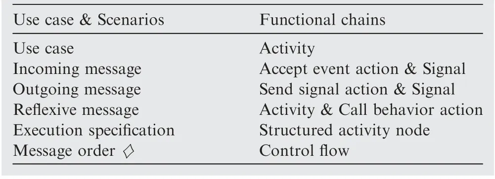
Table 1 Semantics mapping between scenarios and functional chains.
5.1. Experiments and results
During requirement capture, 8 main use cases and 4 actors were identified for the OMS.Among those use cases,the three depicted on the Fig. 7 were used for experiments. Those use cases were chosen to cover important functions and communication aspects of the OMS.
(1) Execute ground tests: this use case provides functionality with the regards to aircraft equipment test management and test execution. This use case has a lot of interactions with aircraft equipment and with maintenance technician. For instance, while the aircraft in on ground,the maintenance technician can execute aircraft equipment test procedures from the OMS. The OMS then retrieve test results and give feedbacks to the technician.
(2) Aircraft Condition Monitoring Function (ACMF): it
provides important functionality with regards to failure messages and health monitoring of aircraft equipment.
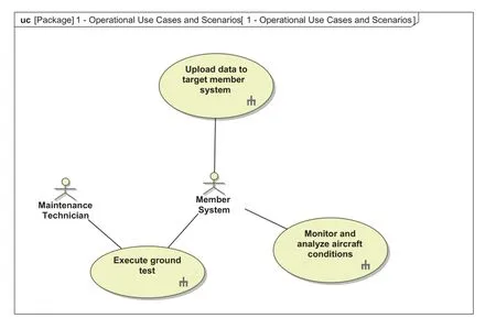
Fig.7 Chosen use cases for experiments.
(3) Upload data to target member system: it provides important functionality with regards to aircraft software equipment configuration and maintenance.
From those 3 use cases 17 operational black-box scenarios were derived, containing 108 functional messages between actors and the OMS. After semantics unification, functional messages were reduced to 71 messages.Then,using the semantics mapping of Table 1,the scenarios were automatically combined to create executable top-level functional chains. An excerpt of functional chains is depicted on the Fig.8.It shows three functional chains containing control flow(dashed arrow)and object flows (continuous arrows). The object flows (functional flows) are added by the engineer since the combining of scenario can only deduce control flow (see Table 1).
Several benefits were identified when applying the approach.The first benefit concerns the semantics clarification:the team was able to work collaboratively to progressively formalize the operational scenarios. The second benefit concerns early functional validation: the team was able to run and debug the operational scenarios and found functional inconsistencies such as missing data or inconsistencies between several scenarios.The third benefit concerns the identification of missing functions, i.e. functions not identified in scenarios, during scenarios combining.
This last point is important since getting complete requirements is mandatory.Finally,the approach provides direct navigation to impacted functions thanks to traceability.
A plugin has been realized for the SysML tool Cameo System Modeler33This plugin enables to check the use cases and the scenarios regarding the causal consistency and the types of the lifeline.The scenario combining,and the automatic synthesis of function definitions and functional chains has been implemented.To map with SysML the algorithm generates five elements for each incoming triggering message:a signal,signal event for signal reception event,an accept event action for the subscription of system waiting for such event, a structured activity node for system reaction on signal reception and control flow between accept event action and structured node to reflect causality.

Fig.8 Functional chains excerpt from execute ground test.
5.2. Discussion
Creating black-box operational scenarios using Sequence Diagrams can be conducted in two ways: either informal or formal. The informal way may lead to inconsistencies concerning use case granularity or functional messages causality. On the contrary, the formal way ensures consistency by construction, helps removing ambiguities in the first iterations and then allows reaching good quality (mature) requirements quickly.34
The proposed approach aims at providing formal blackbox operational scenarios to identify and remove ambiguities early in the development cycle and to support simulation of functional requirements to ease their validation by customer.However,using a formal notation could be a strong constraint.Hence, the engineers first create simple Sequence Diagrams with a small subset of SysML concepts and some limited guidance through basic checking rules (causality, consistency between UC and scenarios). The engineers are free to use natural language to create the messages between the System and the actors. Then, the semantics of the messages is clarified(see Fig. 2). For instance, let us say that a functional message is named Start Request, and that another functional message in another scenario (defined by someone else) is named Start message.In such a case,there is a great chance that both messages represent same semantics (start request): those two messages are unified into one single definition.
Finally, the OMS case study may introduce bias over the interpretation of the results.Indeed,the software nature of this system did not permit to cover all the aspect of a cyberphysical systems. Therefore, continuous aspects of a system should be considered and formalized. In addition, impacts on the simulation when continuous behavior is specified shall be investigated.
6. Conclusions
(1) A SysML method for capturing requirements is developed in this paper. The method starts from stakeholder requirements and reach functional system requirements through formal SysML model.The major concepts have been formalized and linked to SysML concepts and ARP4754A concepts using a meta model-based approach.
(2) The automatic synthesis of functional chains from scenarios permitted to ensure automatic traceability from functions to scenarios.In addition,scenarios combining led to identification of missing functions. The proposed approach permitted to work in team as use cases were designed to be independent. Finally, the automatic synthesis of simulation context and was meaningful to execute and verify the model under design and to prepare V&V activities.
(3) Currently the developed approach does not consider the temporal validity of the functions. The approach shall consider states and modes and add a transformation step to split functional chains into one top level state machine completed with a set of smaller Activity Diagrams.
(4) The proposed approach should also be able to generate textual system functional requirements and functional interfaces. It could be done by using patterns based on functional chains.Those patterns still need to be formalized and the generation shall be automated with special attention to traceability.Finally,the inputs coming from Functional Hazard Analysis (FHA) and Preliminary Aircraft Safety Assessment(PASA)shall also be considered. The links between MBSE and MBSA (Model Based Safety Analysis) should be investigated.
Acknowledgements
This article results from an MBSE Integrated Project Team(IPT).The work was done within COMAC Beijing Aeronautical Science and Technology Research Institute.We are warmly grateful to Jiang XIN for his support to this project. We also kindly thank Jie DAI, Xie MIN, Cary WANG, and Wang CHEN, for the construction of the case study and for their valuable comments.
杂志排行

CHINESE JOURNAL OF AERONAUTICS的其它文章
- Fracture behavior and self-sharpening mechanisms of polycrystalline cubic boron nitride in grinding based on cohesive element method
- A CFD-based numerical virtual flight simulator and its application in control law design of a maneuverable missile model
- A pre-generated matrix-based method for real-time robotic drilling chatter monitoring
- Target-enclosing aきne formation control of two-layer networked spacecraft with collision avoidance
- Measuring the resilience of an airport network
- Distributed intelligent self-organized mission planning of multi-UAV for dynamic targets cooperative search-attack