Numerical simulation of cavitation turbulence in Francis turbine runner with splitter blades
2020-01-03,,,,
, , , ,
(School of Energy and Power Engineering, Xihua University, Chengdu, Sichuan 610039, China)
Abstract: Cavitation will reduce the turbine performance and even damage the turbine components. To verify the effects of splitter blades on improving the cavitation performance, the cavitation flow inside a Francis turbine runner with splitter blades was numerically simulated by using the Singhal cavitation model and the standard k-ε turbulence model. The distributions of static pressure and gas volume fractions on the surface of the runner blades were predicated under different conditions, and the cavitation in the flow field of the runner was analyzed. The results show that the static pressure and gas volume fractions are more uniformly distributed on the short blades than those on the long blades in Francis turbines with splitter blades, and there is almost no cavitation on the short blades; their distributions are more uniform under small flow conditions than those under large flow conditions; and large gas volume fractions are concentrated at the outlet tip near the band on the suction side of the long blade. The installation of splitter blades can improve the cavitation performance of conventional Francis turbines.
Key words: Francis turbine;splitter blades;runner;cavitation;numerical simulation
1 Introduction
Cavitation is a common phenomenon during the operation of hydraulic turbines. It can reduce the turbine performance, cause the erosion of flow components, generate vibration and noise, and even damage turbine components. With the development of hydraulic turbines towards high head and high speed, the research on cavitation has attracted more and more attention.
Numerous researches on cavitation mechanism and cavitation theory have laid a solid foundation for the study of cavitation in hydraulic machinery. PORTISKY[1]provided a new way to solve the problem of viscosity by taking the velocity calculated from the ideal fluid as the approximate velocity of viscous fluid, and then applying the calculated viscous stress on the ideal fluid. By solving the equations of motion during bubble collapse both in the Lagrangian and in the chara-cteristic forms, HICKLING, et al[2]presented the perfect numerical solutions for the flow in the vicinity of a collapsing spherical bubble in water. Then PLESSET, et al[3]designed a numerical method to solve vapor bubble collapse problems lacking spherical symmetry. ARNDT[4]reviewed the physical phenomena of cavi-tation and discussed factors affecting the occurrence of cavitation, such as cavitation nuclei, surface roughness and viscosity. FRANC, et al[5]provided a comprehensive presentation of the phenomena involved in cavitation, explained all types of cavitation developed in real liquid flows, and covered the field of cavitation inception as well as developed cavitation. KUMAR,et al[6]discussed the various aspects related to cavitation in hydro turbines, the different causes for the declined performance and efficiency of the hydro turbines, and the suitable remedial measures suggested by various investigators. HUANG, et al.[7]conducted mixed nume-rical simulation to the 3D cavitating turbulent flow field in a Francis turbine, and obtained the distribution of pressure and cavitation bubble volume components on the blade under different conditions. ZHANG, et al[8]simulated the cavitating status of a Francis turbine at different cavitation coefficients, and calculated the cri-tical cavitation coefficient. Based on the modified mass transfer equation, LIU, et al[9]numerically simulated the cavitation in a model Francis turbine on different Thoma numbers.
Numerical simulations are considerably helpful to evaluating the cavitating flows and the cavitation performance. However, the flow inside Francis turbines with splitter blades is more complicated than other conventional Francis turbines, and the study of cavitation in them is few. With the multiphase cavitation mode-ling approach, a basic two-phase cavitation model co-nsists of the standard viscous flow equations go-verning the transport of mixture or phases, and a conventional turbulence model were developed. To have an insight into the nature of cavitating flows in Francis turbines with splitter blades, the Singhal cavitation model and the standardk-εturbulence model were used to simulate the cavitation flow in the turbine. The main reason to choose the Singhal cavitation model instead of the Zwart-Gerber-Belamri and Schnerr and Sauer models is that the effects of turbulence and noncondensable gases are taken into account in the Singhal cavitation model, besides it has the capability to account for multiphase flows, the effects of slip velocities between the liquid and gas phases, and the thermal effects and compressibility of both liquid and gas phases.
2 Mathematical model
2.1 Control equations
The no-slip model of mixed fluid was used to si-mulate the gas-liquid two-phase flow in the turbine, namely there is no relative sliding between the liquid phase and the cavitation phase. The continuity equation and momentum equation of the two-phase flow can be expressed as follow:
Continuity equation of the mixture is
(1)
Momentum equation of the mixture is
(2)
wheretis the time,xiis the coordinate component,vis the velocity magnitude of the mixture,pis the pressure of the flow field,gis the acceleration of gravity,ρmis the density of the mixture,ρm=φlρl+φvρv+φgρg,φl,φvandφgare volume fractions of water, water vapor (cavitation bubbles) and noncondensable gas (φl+φv+φg=1),ρl,ρvandρgare densities of them, separately,μmis the dynamic viscosity of the mixture, and subscriptsiandjare tensor coordinates.
2.2 Turbulence model
Turbulence kinetic energykequation:
(3)
Dissipation rate of the turbulence kinetic energyεequation:
(4)
whereμtis the eddy viscosity or turbulent viscosity,μt=ρmCμk2/ε,Cμ=0.09,σkandσεare turbulent Prandtl numbers,σk=1.0 andσε=1.3,Ce=0.02,Cc=0.01,C1ε=1.44,C2ε=1.92, andC3ε= tanh(vx/vz),kis the turbulence kinetic energy,εis the turbulence eddy dissipation,Gkrepresents the turbulence kinetic energy generated by the average velocity gradient,Gbrepresents the turbulence kinetic energy gene-rated by the buoyancy force, andYMrepresents the contribution of transitional diffusion to the turbulence eddy dissipation during compressible turbulent flow.
2.3 Transport equations
Transport equation of the water vapor phase (cavitation phase) obtained from the continuity equation:

(5)
whereγis the effective exchange coefficient;eandcare generation rate and condensation rate of water vapor, separately.
Transport equation of the noncondensable gas phase in water:
(6)
2.4 Cavitation model
SINGHAL, et al[10]introduced the simplified Rayleigh-Plesset equation into the cavitation model, and obtained the following cavitation model:
Ifp≤pv, bubble growing (cavitation) process:
(7)
Ifp>pv, bubble condensation (collapse) process:
(8)
Cavitation flow involves a phase transition process, so there will be a very large density change in the low pressure area. Singnal cavitation model takes into account all the major factors affecting cavitation. wherepvis the saturation pressure of water vapor, empirical coefficientsCe=0.02,Cc=0.01, andσis the coefficient of surface tension. This model has been used to simulate the solid-liquid two-phase turbulent flow in the runner of Francis turbines used in Jinping II Hydropower Station on Yalong River in China, and has proved reliable[11].
3 Geometric model and boundary conditions
3.1 Geometric model
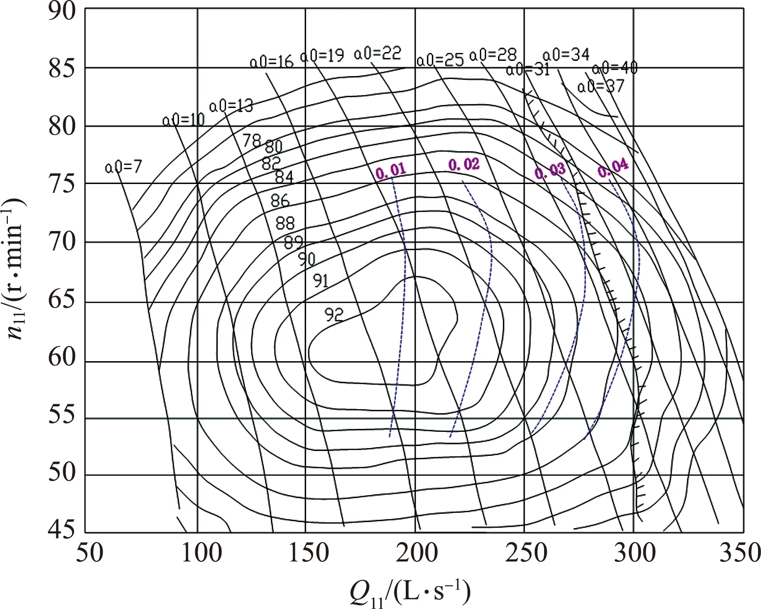
The real type HLA542-130 Francis turbine with splitter blades was taken as the calculation model. The parameters of this turbine are as follows: runner diameterD1=1,300 mm, design headHd=250 m, design flow rateQd=5.07 m3/s, rated speedn=750 r/min, number of long and short bladesZ1=Z2=15, separately, number of stay vanesZ3=9, and number of guide vanesZ4=16. The cavitation performance curve of the turbine is shown in Fig.1.

Fig.1 Cavitation performance curve of HLA542-130 Francis turbine with splitter blades
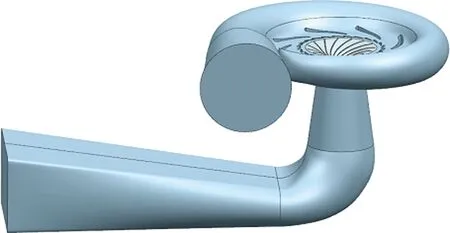
According to the design parameters, the spiral casing, stay vanes ring, runner and draft tube of the turbine were modeled. The geometric model of the whole flow passage is shown in Fig.2.

Fig.2 3D model of whole flow passage of turbine
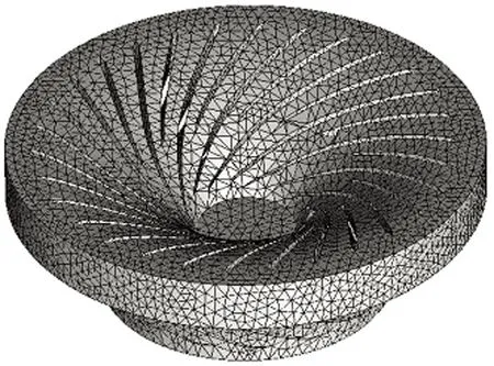
The unstructured grid was used for the whole flow passage, the near wall area was densified separately, and the dynamic-static coupling was adopted for the interface between the runner and the stay vanes ring. The grid division of the runner is shown in Fig.3. According to the variation pattern of the hydraulic performance with the number of grids, the grid indepen-dence was verified when the variation rate of efficiency is less than 0.5%. The total computational grids on the whole flow passage of the turbine is 1.46 million.

Fig.3 Grids of runner
3.2 Boundary conditions
The calculation results of single phase flow at non-cavitation conditions were taken as the initial values to increase the convergence rate of calculation. The velocity inlet and pressure outlet were used as the boundary conditions, and the no-slip conditions was adopted for the solid wall in the flow passage. The initial gas volume fractions at the inlet and outlet were set as 0.
4 Calculation and results analysis
The Singhal cavitation model and the standardk-εturbulence model were used to numerically simulate the cavitation flow in the Francis turbine with splitter blades. In view of the proneness of cavitation under off-design conditions, the small flow condition (flow rateQ=0.5Qd, guide vane openinga=34.7 mm) and the large flow condition (flow rateQ=1.2Qd, guide vane openinga=54.7 mm) were selected for calculation and analysis.
4.1 Distribution of static pressure on blade surface
The calculation results of static pressure distribu-tion on the leading face and trailing face of the long blades are shown in Fig.4 and Fig.5. Under small flow conditions, on the leading face of the long blade, the static pressure is evenly distributed from the inlet tip to the outlet tip, and a small low pressure zone is generated at the outlet tip near the crown. On the trailing face of the long blade, a large low pressure zone is generated at the outlet tip near the crown. Meanwhile, an elliptic low pressure zone is formed near the band indicating the flow separation at this region.

Fig.4 Static pressure on leading face of long blade

Fig.5 Static pressure on trailing face of long blade
Under large flow conditions, on the leading face of long blade, low pressure zones are generated at the outlet tip near the band and there are comparatively small lateral flows. Meanwhile, the negative pressure zone at the outlet tip indicates the existence of flow separation. On the trailing face of the long blade, large negative pressure zones are generated near the outlet tip indicating the existence of vortices.
The calculation results of static pressure distribu-tion on the leading face and trailing face of the short blades are shown in Fig.6 and Fig.7.

Fig.6 Static pressure on leading face of short blade

Fig.7 Static pressure on trailing face of short blade
Under small flow conditions, on the leading face of the short blade, the static pressure is evenly distri-buted from the inlet tip to the outlet tip, but there is barely a low pressure zone on the leading face. On the trailing face of the short blade, the pressure reducing amplitude from the inlet tip to the outlet tip increases.
Under large flow conditions, on the leading face of short blade, a small low pressure zone is generated at the inlet tip indicating lateral flows in this area, and in the meantime a low pressure zone is generated at the outlet tip near the crown. On the trailing face of the short blade, the static pressure is evenly distributed. Only two small low pressure zones are generated at the outlet tip one near the crown and the other near the band indicating the generation of backflow.
In short, the distribution of static pressure on the short blades is more uniform than that on the long blades. This means that the installation of splitter blades can help to make the static pressure distribution uniform. Meanwhile, the distribution of static pressure under small flow conditions is more uniform than those under large flow conditions, which indicates that cavitation tendency is increased under large flow conditions.
4.2 Distribution of gas volume fractions on blade surface
The calculation results of gas volume fractions distribution on the leading face and trailing face of the long blades are shown in Fig.8 and Fig.9.The distribution of gas volume fractions also indicates the cavitation degree. The larger the gas volume fraction is, the worse the cavitation degree will be.
Under small flow conditions, on the leading face of the long blade, there are a few star-shaped cavitation bubbles at the inlet tip near the crown indicating flow separation in a small scope due to the impact of flow on the inlet tip, which is consistent with the results of the static pressure distribution; and there are star-shaped cavitation bubbles at the outlet tip near the crown indicating flow separation in the low pressure zone at the outlet tip. However their influence on the flow field is small due to their small gas volume fractions. On the trailing face of the long blade, there are a small amount of cavitation bubbles at the inlet tip indicating flow separate in this area; and there are a series of cavitation bubbles at the outlet tip near the band, which is consistent with the results of the static pressure distribution. However, cavitation will not occur because the pressure on the blade surface is larger than the cavitation pressure.

Fig.9 Gas volume fractions on trailing face of long blade
Under large flow conditions, there is hardly any cavitation bubbles on the leading face of the long blade, but there are a large number of linear bubbles on the trailing face of the long blade at the outlet tip. The gas volume fraction in some area near the band even reaches to 75%. This means that cavitation is serious in this area, which will have a serious impact on the operation of the unit.
The calculation results of gas volume fractions distribution on the leading face and trailing face of the short blades are shown in Fig.10 and Fig.11.
Under small flow conditions, on the leading face of the short blade, there are some star-shaped cavitation bubbles at the inlet tip near the crown, which indicates certain flow separation at the inlet tip due to flow impact. But their influence on the flow field is small due to small gas volume fractions. On the trailing face of the short blade, there are a few cavitation bubbles at the outlet tip near the band, but their influe-nce on the flow field is small, too.

Fig.10 Gas volume fractions on leading face of short blade
Under large flow conditions, on the leading face of the short blade, there are a few star-shaped cavitation bubbles at the outlet tip near the band, which indicates a small scale flow separation due to the flow impact on the inlet tip, but they will not lead to cavitation due to the small gas volume fractions. On the trailing face of the short blade, there are cavitation bubbles at the outlet tip near the band, and the gas volume fraction is only large in a small area.
In short, the distribution of gas volume fractions on the short blades is more uniform than that on the long blades. There is hardly an area with particularly large gas volume fractions on the short blades, which proves the good cavitation performance by the instal-lation of splitter blades. At the same time, the distribution of gas volume fractions under small flow conditions is more uniform than that under large flow conditions. Under small flow conditions, the gas volume fractions are small, and so is their influence on the flow. Under large flow conditions, the gas volume fractions are large at the outlet tip near the band on the trailing face of the long blade, and cavitation is the worst in this area.
5 Conclusions
The cavitation flow in a Francis turbine with splitter blades were numerically simulated to obtain the distributions of static pressure and gas volume fractions on the blade surface.
1) The distributions of static pressure and gas vo-lume fractions are the most uniform on the short blades under small flow conditions and the least uniform on the long blades under large flow conditions.
2) Low pressure zones exist at the outlet tip on both sides of the long blades under small and large flow conditions, especially on the trailing face. Flow separation and vortices are generated in these areas. By comparison, low pressure zones only exist at the outlet tip on both sides of the short blades under large flow conditions, and the areas of the low pressure zones are smaller than those on the long blades.
3) As a result of impact, flow separation will occur at the inlet and outlet tips of both the long and short blades under small flow conditions. Cavitation bubbles will form at these areas, but their influence on the flow field is small due to their small gas volume fractions. Under large flow conditions, cavitation bubbles will only form at the outlet tips of the long and short blades. Although the amount of cavitation bubbles seems to be larger on the short blades, but their influence on the flow field is small due to their small gas volume fractions. However, the gas volume fractions at the outlet tip on the trailing face of the long blade are large (even reaching to 75%). Cavitation is the worst only in this area.
4) Compared with conventional Francis turbines of the same type, the cavitation performance of the Francis turbines with splitter blades is much better.
