Intense Yellow Emission from Gd0.5–yTb1.5REyW3O12 (RE=Eu, Sm) Phosphors Tuned through Full Range Doping
2019-12-16DAIYanNanYANGShuaiSHENYangSHANYongKuiYANGFanZHAOQingBiao
DAI Yan-Nan, YANG Shuai, SHEN Yang, SHAN Yong-Kui, YANG Fan, ZHAO Qing-Biao
Intense Yellow Emission from Gd0.5–yTb1.5REW3O12(RE=Eu, Sm) Phosphors Tuned through Full Range Doping
DAI Yan-Nan1, YANG Shuai1, SHEN Yang2, SHAN Yong-Kui1, YANG Fan1, ZHAO Qing-Biao2
(1. School of Chemistry and Molecular Engineering, East China Normal University, Shanghai 200241, China; 2.Key Laboratory of Polar Materials and Devices (MOE), Department of Optoelectronics, East China Normal University, Shanghai 200241, China)
Yellow emission phosphors play an important role in fabrication of near ultraviolet (NUV) chip pumped white light emitting diodes (W-LEDs). In this study, doping of Gd2W3O12host with Tb3+and Eu3+/Sm3+were used for obtaining yellow light emission. The excitation of Gd3+typically is in deep ultraviolet region, but Gd3+in Gd2W3O12does not emit under the excitation of 382 nm, thus Gd3+does not interfere with the emission from Tb3+and Eu3+/Sm3+for obtaining yellow emission. Due to the similar ionic radii, the doping of Gd3+by Tb3+can be achieved in the full concentration range, and at the optimal concentration of 75mol% Tb3+, green emission with reasonably high internal quantum efficiency of 37.6% was obtained. With the optimal doping concentration of Tb3+, Eu3+/Sm3+was co-doped in the Gd2W3O12host, and bright yellow emission with IQE of 39.6% and 47.8% were obtained. The yellow phosphors of Gd0.494Tb1.5Eu0.006W3O12and Gd0.494Tb1.5Sm0.006W3O12were used to fabricate W-LED devices with NUV-blue chips. Thus, Gd0.5–yTb1.5REW3O12(RE=Eu, Sm) phosphors are candidates as the yellow phosphors for fabricating W-LED devices. Additionally, the full-range doping strategy can be used in other systems for obtaining efficient phosphors.
solid state synthesis; photoluminescence; tungstate; rare earth; internal quantum efficiency
White light emitting diodes (W-LEDs) have received much attention for their high efficiency, long service life and small volume[1-3].There are primarily three approaches for obtaining W-LEDs, including tri-color (red, green, blue) diode chips[4], blue chips coated with yellow phosphors[5], and ultraviolet (UV) chips coated with RGB phosphors[6]. The LED chips used for solid state lighting can typically provide near ultraviolet (NUV) excitation in the region of 380–420 nm. Therefore, the phosphors that can be efficiently excited in this region are desired.
The commercialized cerium (III)-doped yttrium aluminum garnet (YAG: Ce3+) emit strong yellow light under blue excitation from InGaN chips[7]. Besides, some other novel Ce3+doped phosphors with high quantum efficiency had been reported in recent years[8-9]. However, the preparation of Ce3+doped phosphors requires a reducing atmosphere, which inevitably adds to the cost. Moreover, Ce3+tends to be oxidized to the tetravalent state if exposed to air. Thus, it is desired to develop new phosphors that can be prepared in ambient atmosphere. Yellow light can be obtained by adjusting the ratio of green light to red light. Tb3+and Eu3+(or Sm3+) ions can be excited by NUV, emit green and red light, respectively[10-11]. Therefore, it is possible to realize yellow light emission under NUV excitation by adjusting the doping ratio of Tb3+/Eu3+or Tb3+/Sm3+in proper hosts.
Rare earth ion based tungstates have drawn increasing attention for their low phonon energy and high thermal stability[12-13]. Since the electronic configuration of Gd3+(4f7) is half full, the f-f transition (8S7/2→6IJ) of Gd3+generally takes place at deep ultraviolet region, and Gd3+generally does not exhibit emission in visible range[14]. Gd2W3O12can provide suitable substitution sites for rare earth ions, thus can function as the host of rare earth ion doped phosphors. As the ionic radius of Tb3+, Eu3+and Sm3+are very close to that of Gd3+[15], those rare earth ions were introduced to substitute the positions of Gd3+ions in Gd2W3O12. The substitution of Gd3+by Tb3+can perform in the entire range, allowing the fine tuning of the optimal doping rate in order to obtain the maximum IQE for the green emission. Eu3+and Sm3+ions can be efficiently excited by NUV/blue light and emit in the red range[16-17]. With the combination of green emission from Tb3+and red emission from Eu3+/Sm3+, co-doping Eu3+(or Sm3+) with Tb3+is another strategy for obtaining yellow emission, which does not require reducing environment.
In this study, the photoluminescence properties of Eu3+(or Sm3+) and Tb3+co-doped Gd2W3O12phosphors with yellow light emission are reported. The IQE of Gd0.494Tb1.5Eu0.006W3O12and Gd0.494Tb1.5Sm0.006W3O12are 39.6% and 47.8%, respectively. Furthermore, they can be synthesized under ambient atmosphere, thus avoiding the requirement of reducing atmosphere. Gd0.494Tb1.5Eu0.006W3O12and Gd0.494Tb1.5Sm0.006W3O12are promising candidates for yellow phosphors. The full-range doping approach can be used in search for novel phosphors with high efficiency.
1 Experimental
A series of Gd2W3O12: Tb3+, Eu3+(or Sm3+) phosphors were synthesized by traditional high temperature solid state synthesis. The starting materials of Tb4O7(Adamas Reagent, 99.99%), WO3(Adamas Reagent, 99.90%), Gd2O3(Adamas Reagent, 99.99%), Eu2O3(Adamas Reagent, 99.90%) and Sm2O3(Adamas Reagent, 99.90%) were weighed in stoichiometric ratio and thoroughly ground in an agate mortar. After thoroughly mixing, the reactants were transferred to an alumina crucible and heated at 600℃ for 8 h. After cooling to room temperature, the obtained intermediate products were reground and calcined at 1000℃ for 24 h.
The XRD patterns were collected by a Bruker D8 diffractometer with CuKα (=0.154059 nm) radiation at 40 kV and 40 mA. The excitation and emission spectra of Gd2W3O12: Tb3+, Eu3+(or Sm3+) phosphors were collected with a Hitachi F4500 Fluorometer. The internal quantum efficiencies (IQE) were measured by Edinburgh (EI) FS5 fluorometer equipped with an integrating sphere. The IQE was calculated with equation (1):

whereBis the emission integral of the sample,Ais the emission integral of the blank stander,Ais the absorption integral of the blank stander andBis the absorption integral of the sample. A polytetrafluoroethylene plate was used as the reference.
2 Results and discussion
2.1 Structural analysis
Gd2–xW3O12:Tb3+(= 0, 0.25, 0.75, 1.00, 1.25, 1.50, 1.75, 2.00) phosphors were synthesized by high temperature solid state synthesis. The crystal structures of Tb2W3O12and Gd2W3O12have been reported[18]. The crystal structure of the as-prepared Gd2W3O12belongs to the monoclinic system. The space group is C2/c with the following lattice parameters:=0.7811 nm,=1.1629 nm,= 1.1537 nm,==90°,=109.719°. In Gd2W3O12, each Gd atom is coordinated with 8 O atoms, forming a [GdO8] polyhedron without inversion center. As shown in Fig. 1(a, b), each [GdO8] polyhedron shares one side with two nearest [GdO8] polyhedron. Thus a one-dimensional chain structure is formed, which plays an important rolefor the high concentration quenching of Tb3+in Gd2W3O12.
Fig. 2 shows the XRD patterns of Gd2W3O12, TbGdW3O12and Tb2W3O12, which are consistent with the JPCDS card of Gd2W3O12(JPCDS #23-1076). The cell parameters of Tb2W3O12, Gd2W3O12only have a minor difference, and the crystal structure of Tb2W3O12and Gd2W3O12are similar. Therefore, the doping ratio of Tb3+ions in Gd2W3O12can range from 0 to 100mol%.
The ionic radii of both Sm3+(CN=8,=0.1079 nm) and Eu3+(CN=8,=0.1066 nm) ions are also similar to Gd3+(CN=8,=0.105 nm) ions[15]. Therefore, co-doping of Sm3+or Eu3+in Tb3+doped Gd2W3O12is feasible. Apparently, in order to obtain yellow emission, doping on the Gd3+site has a unique advantage in that both the doping ratios of Tb3+as the green emission source and the doping ratios of Eu3+/Sm3+as the red emission source can be tuned in a broad range. This allows fine tuning of both the overall emission wavelengths and emission intensity.
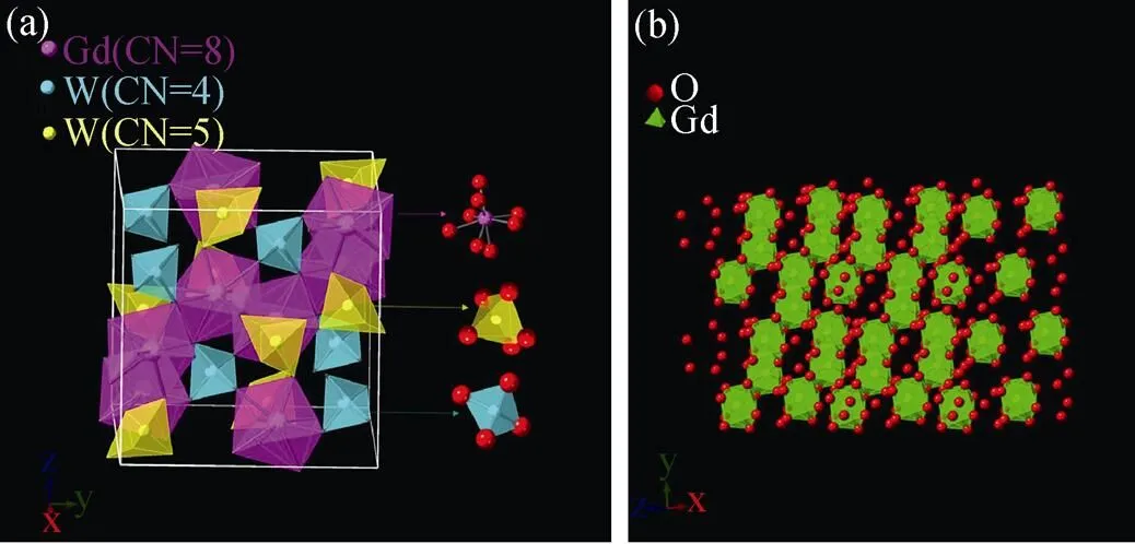
Fig. 1 (a) The polyhedron models of the crystal structure of Gd2W3O12 from perspectives of x axis, (b) the one-dimensional chain structure of [GdO8] polyhedrons
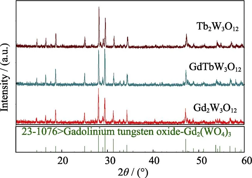
Fig. 2 XRD patterns of Gd2W3O12, TbGdW3O12 and Tb2W3O12
2.2 Luminescence property
Fig. 3(a, b) show the excitation spectra of Gd2–xW3O12:Tb3+phosphors monitored with 549 nm emission and the concentration dependent excitation intensity, respectively. There is a broad excitation band shorter than 320 nm which belongs to the charge transfer (CT) between W and O. The excitation at 321 nm (7F6→5D0), 342 nm (7F6→5D1), 361 nm (7F6→5D2), 372 nm (7F6→5D3), and 382 nm (7F6→5D4) belong to the f–f transition of Tb3+ions[19]. With increasing concentration of Tb3+ions up to 75mol% (when=1.50), the excitation intensity gradually enhances. As the concentration of Tb3+ions continue to increase, the excitation intensity gradually decreases. With Gd3+ions entirely replaced by Tb3+ions, Tb2W3O12shows a weak excitation.
Fig. 4(a, b) show the emission spectra at 382 nm excitation and the concentration dependent emission intensities of Gd2–xW3O12:Tb3+(=0.25, 0.75, 1.00, 1.25, 1.50, 1.75, 2.00) phosphors. The sharp peaks at 485, 549, 575 and 610 nm correspond to the relaxation processes (5D4→7F6,5D4→7F5,5D4→7F4and5D4→7F3)of Tb3+ions, respectively[20]. As shown in Fig. 4(a, b), with the doping amount of Tb3+ions increasing to 75mol% (=1.50), the emission intensity at 549 nm gradually increases, and the IQE of Tb1.5Gd0.5W3O12enhances to 37.6%. The emission intensity at 549 nm gradually decreases with further increasing of the doping amount of Tb3+. With the full occupancy of Tb3+, the concentration quenching is significant and the emission intensity of Tb2W3O12is very weak, and the IQE of Tb2W3O12is only 12.6%.
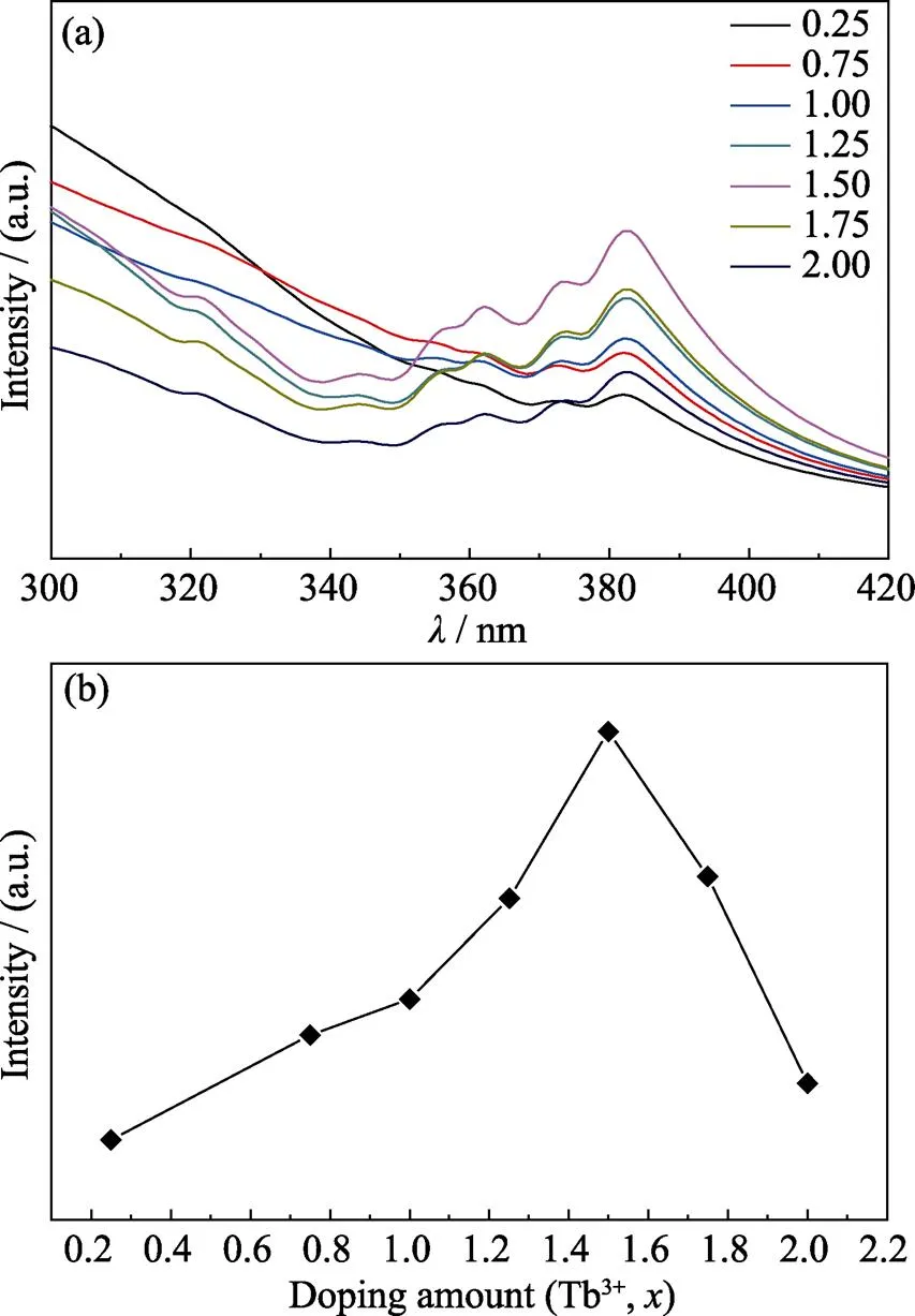
Fig. 3 (a) The excitation spectra of Gd2–xW3O12: xTb3+ (x= 0.25, 0.75, 1.0, 1.25, 1.5, 1.75, 2.00) monitored with 549 nm emission; (b) The concentration dependent excitation intensity of 7F6→5D4 transition of Tb3+ at 382 nm in Gd2–xW3O12: x Tb3+ (a) Coloful spectra are available on website
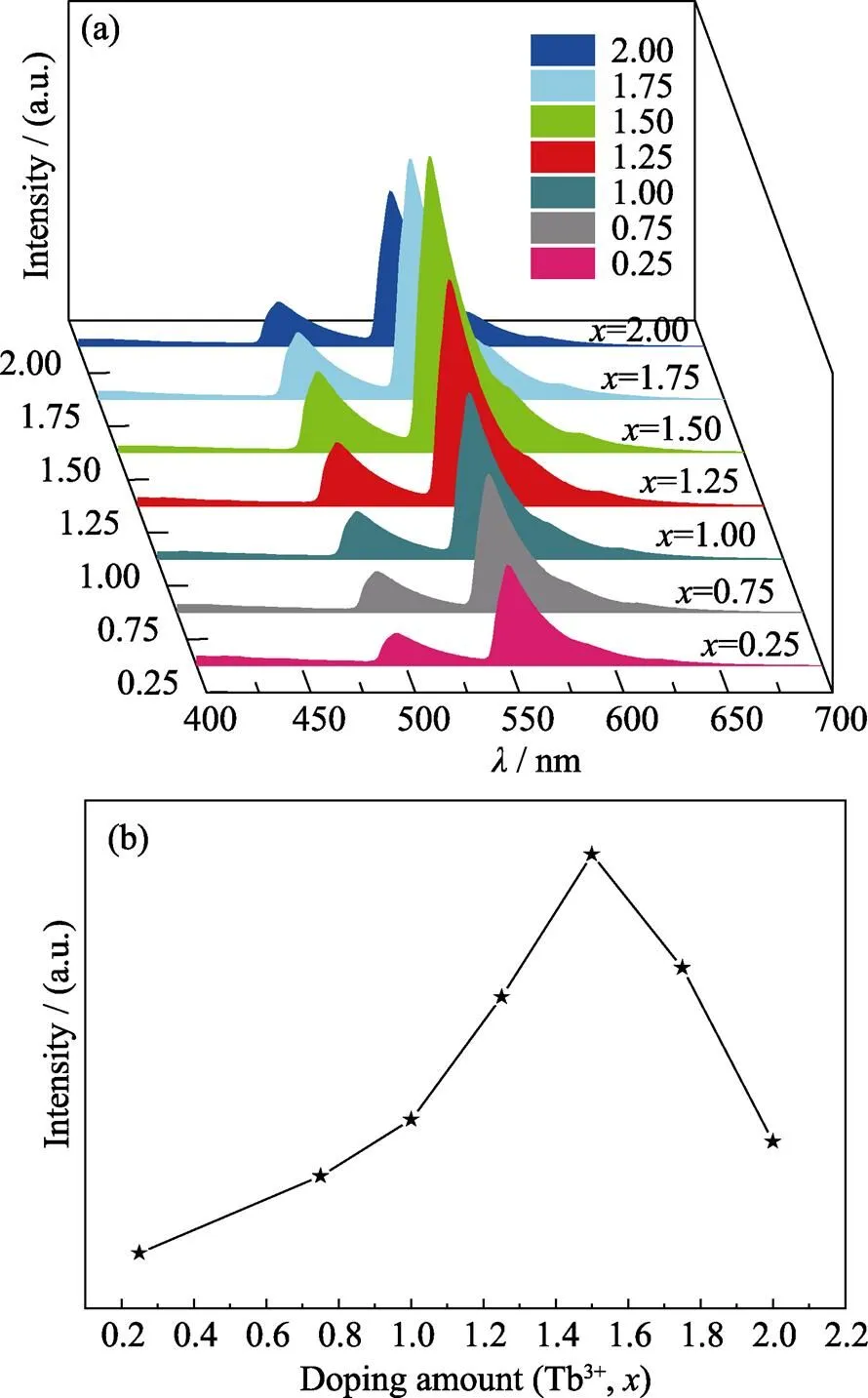
Fig. 4 (a) The emission spectra of Gd2–xW3O12: xTb3+ (x=0.25, 0.75, 1.00, 1.25, 1.50, 1.75, 2.00) phosphors under 382 nm ultraviolet excitation; (b) The concentration dependent 549 nm emission intensity of Gd2–xW3O12: xTb3+ (where x=0.25, 0.75, 1.00, 1.25, 1.50, 1.75, 2.00) phosphors
The concentration quenching of Tb3+doped Gd2W3O12occurs at a rather high concentration of 75mol%. Typically, the optimal doping concentration of rare earth activators for luminescence is in the range of 1mol%– 20mol%. Realizing very high quenching concentration can be a strategy for realizing bright green emission.
It is intriguing to figure out the cause for the high concentration quenching of Tb3+doped Gd2W3O12.The mechanism of self-concentration quenching (SCQ) of Tb3+and Eu3+ions in LaMgB5O10have been reported[21]. Since edge-sharing [LaO10] polyhedron in LaMgB5O10form isolate chains, one-dimensional interactions between Tb3+ion or Eu3+ions occurs, which lead to a high self-quenching concentration. The high quenching concentration of Gd2–xTbW3O12phosphors can be attributed to the crystal structure of Gd2W3O12host. As shown in Fig. 2(b), the nearest edge-sharing [GdO8] polyhedrons form one-dimensional chains. In general, the concentration quenching of Tb3+ion is due to the non-radiative energy transfer between Tb3+ions[22-23]. Owing to the little differences between5D3→5D4and7F6→7F0of Tb3+, the cross relaxation process was described as Equation (2):
Tb3+(5D3) + Tb3+(7F6)→Tb3+(5D4) + Tb3+(7F0) (2)
Thus, Tb3+ion in the excitation state of5D3would release to a lower excitation state of5D4and the neighboring Tb3+ion in the ground state of7F6would be excited to the excitation state of7F0. As a result, the neighboring Tb3+ion act as quenching center which lead to the quenching of Tb3+ion. In such one-dimensional structure, the energy transfer can lead to concentration quenching at a very high concentration.
The critical distance (c) between Tb3+ion was calculated by the concentration quenching method, with the following formula (Eq. (3)) proposed by Blasse[24]:
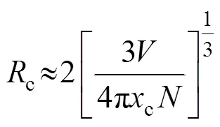
whereis the volume of crystallographic unit cell,cis the critical concentration andis the lattice site number in the unit cell which can be replaced by sensitizers. In Gd2W3O12,=0.493278 nm3,=8, andc=0.75. Thecof Tb3+ions is thus calculated to be 0.539 nm. In general, for energy transfer process, the exchange interaction and multipole interaction are two dominant mechanisms[25]. Exchange interactions generally take place over the distance shorter than 0.5 nm[26]. Since the critical distance of Tb3+ions in Tb2W3O12is 0.539 nm, which is close to 0.5 nm, exchange interaction is expected to play the dominant role in the energy transfer process.
Due to the red emission under NUV excitation, Eu3+and Sm3+ions were utilized to adjust the CIE coordinates of phosphors to yellow region. Fig. 5(a, b) show the excitation spectra of Eu3+and Sm3+doped Gd0.5Tb1.5W3O12phosphors, respectively. Since the excitation bands of Eu3+and Sm3+ions overlap with that of Tb3+, the excitation band of Eu3+or Sm3+cannot be differentiated in the excitation spectra. As shown in Fig. 5(a, b), due to the competition between Tb3+and Eu3+(Sm3+) ions, the excitation intensities of Tb3+ions decrease as doping concentration of Eu3+and Sm3+ions increase. The strongest excitation peaks of both Eu3+and Sm3+doped Gd0.5–yTb1.5REW3O12phosphors locate at 382 nm.
Fig. 5(c, d) show the emission spectra of Gd0.5–yTb1.5REW3O12phosphors doped with Eu3+and Sm3+at 382 nm excitation. In Fig. 5(c), there are two emission peaks at 598 and 619 nm, which correspond to the5D0→7F1and5D0→7F2transitions of Eu3+ion, respectively. As the doping amount of Eu3+ion increases to 0.010, the emission intensity at 619 nm increases. Yet, as the doping amount of Eu3+further increases, the concentration quenching of Eu3+ions occurs.
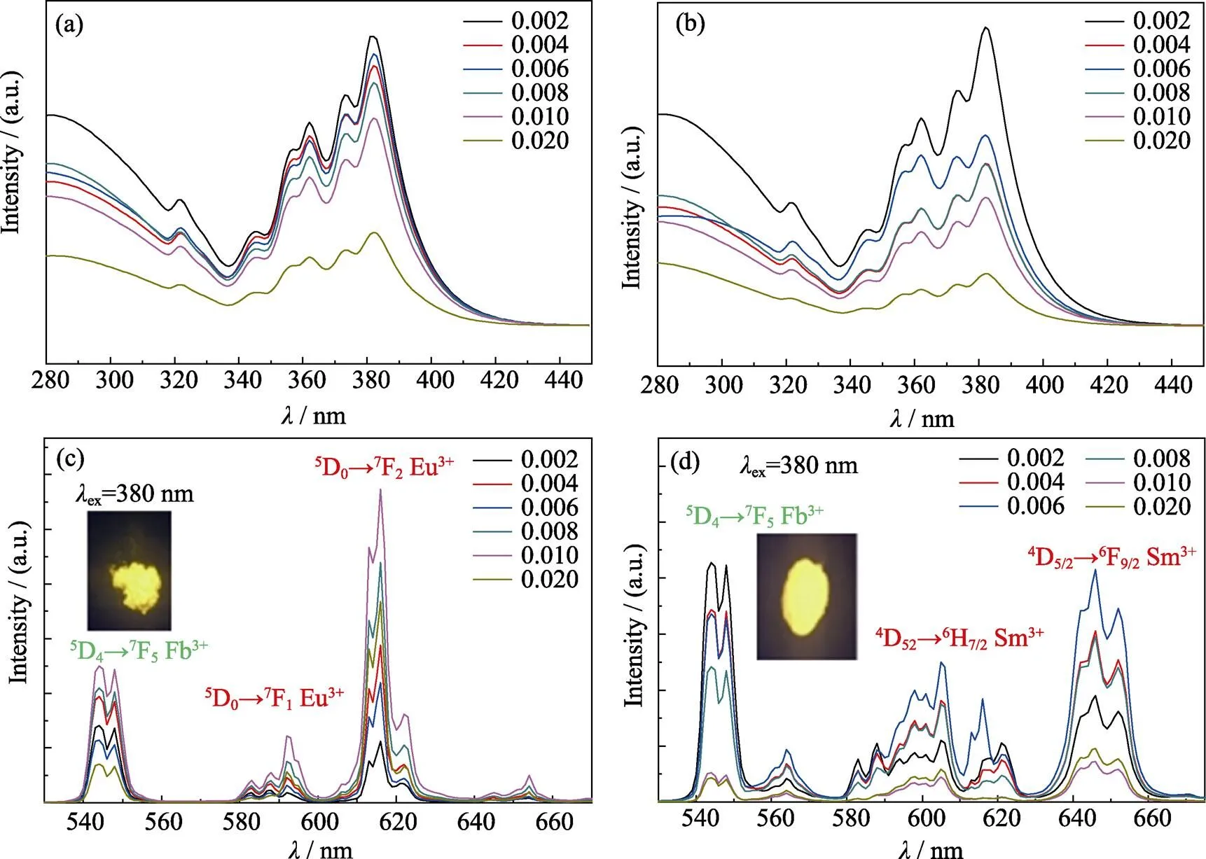
Fig. 5 (a, b)The excitation spectra of Gd0.5–yTb1.5REyW3O12 (RE=Eu, Sm), (c, d) the emission spectra of Gd0.5–yTb1.5REyW3O12 (RE=Eu, Sm) with 382 nm excitation
Colourful spectra are available on website
The electric dipole transition of5D0→7F2emission of Eu3+ion belongs to the hypersensitive transition and is very sensitive to surrounding environment[27]. In Fig. 5 (c), the electric dipole transition of5D0→7F2(619 nm) emission intensity is significantly stronger than the peak intensity at 598 nm, which indicates that the doping position of Eu3+has no inversion center. As shown in Fig. 5(d), besides the characteristic emission of Tb3+ion in 549 nm (5D4→7F5), the emission peaks of Sm3+are also present in the emission spectrum of Gd0.5–yTb1.5SmW3O12phosphors. Those emission peaks at 610 (4G5/2→6H7/2) and 650 nm (4G5/2→6H9/2) correspond to the f-f transition of Sm3+. With the increasing concentration of Sm3+ion, the emission intensity of Tb3+ion decrease, and Sm3+ion achieved the strongest emission at the concentration of 0.3mol%. Since the emission intensity ratio of Tb3+/Eu3+and Tb3+/Sm3+changes with the concentration of Eu3+and Sm3+, the CIE coordinates of both Gd0.5–yTb1.5EuW3O12and Gd0.5–yTb1.5SmW3O12phosphors vary from green to yellow region. Thus, yellow light emission under NUV light excitation is realized by adjusting the concentration of Eu3+or Sm3+ion in Gd0.5–yTb1.5REW3O12(RE=Eu, Sm) phosphors.
As shown in Table 1, the IQE of both Gd0.494Tb1.5Eu0.006W3O12and Gd0.494Tb1.5Sm0.006W3O12are reasonably high, although it still needs improvement. Moreover, the synthesis of Gd0.494Tb1.5Eu0.006W3O12and Gd0.494Tb1.5Sm0.006W3O12can be performed in ambient atmosphere, as opposed to the reducing environment that Ce (III) containing compounds require. Thus, Gd0.494Tb1.5Eu0.006W3O12and Gd0.494Tb1.5Sm0.006W3O12can be used as yellow light emission phosphors to fabricate W-LED device.
2.3 CIE coordinates
The 1931 CIE chromaticity diagram of Gd2–xTbW3O12(=0, 0.25, 0.75, 1.00, 1.25, 1.50, 1.75, 2.00) and Eu3+/Sm3+doped Gd0.5–yTb1.5REW3O12(RE=Eu, Sm;=0, 0.002, 0.004, 0.006, 0.008, 0.010, 0.020) phosphors are shown in Fig. 6(a-c), respectively. As shown in Fig. 6(a), the 1931 CIE coordinatesare constantly close to (0.14, 0.56) with increasing concentration of Tb3+. As shown in Fig. 6(b, c), due to the emission of Eu3+and Sm3+ions, the introduction of both Eu3+and Sm3+has significant influence on the color coordinates of Gd0.5–yTb1.5REW3O12(RE=Eu, Sm;=0, 0.002, 0.004, 0.006, 0.008, 0.010, 0.020). Table 2 lists the CIE coordinates of Gd0.5–yTb1.5EuW3O12and Gd0.5–yTb1.5SmW3-O12with different Eu3+or Sm3+concentration. The 1931 CIE coordinates of Gd0.494Tb1.5Eu0.006W3O12and Gd0.494Tb1.5Sm0.006W3O12are (0.491, 0.472), (0.510, 0.456), respectively, both belonging to the yellow region.
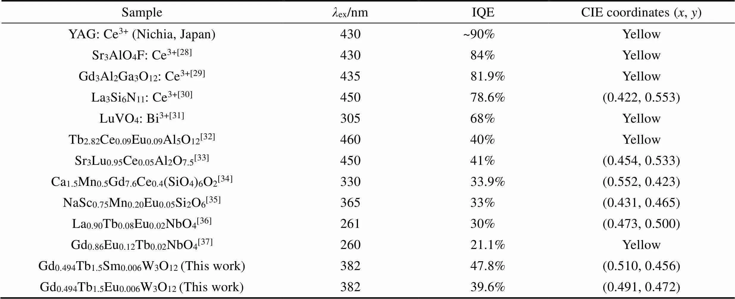
Table 1 Comparison of the IQE and CIE coordinates of Gd0.5–yTb1.5REyW3O12 (RE=Eu, Sm) with other yellow phosphors

Fig. 6 The 1931 CIE coordinates diagram of (a) Gd2–xTbxW3O12 (x=0, 0.25, 0.75, 1.00, 1.25, 1.50, 1.75, and 2.00), (b) Gd0.5–yTb1.5EuyW3O12 (y=0, 0.002, 0.004, 0.006, 0.008, 0.010, and 0.020) and (c) Gd0.5–yTb1.5SmyW3O12 (y=0, 0.002, 0.004, 0.006, 0.008, 0.010, and 0.020). The inserts in (b) and (c) are W-LED (1W), which was fabricated by Gd0.494Tb1.5Eu0.006W3O12 or Gd0.494Tb1.5Sm0.006W3O12 phosphors and NUV-blue chip, respectively

Table 2 The CIE coordinates of Gd0.5–yTb1.5REyW3O12 (RE=Eu, Sm)
3 Conclusion
Gd2–xTbW3O12(=0, 0.25, 0.5, 0.75, 1.0, 1.25, 1.50, 1.75, 2.00) and Gd0.5–yTb1.5REW3O12(RE=Eu, Sm;=0.002, 0.004, 0.006, 0.008, 0.010, 0.020) phosphors were prepared by high temperature solid state synthesis. For the green emitting Gd2–xTbW3O12phosphors, with very close ionic radii of Tb3+with Gd3+, the doping can be tuned in the entire concentration range, allowing the access to the optimum IQE of 37.6%. Gd0.494Tb1.5Eu0.006W3O12and Gd0.494Tb1.5Sm0.006W3O12emit bright yellow light under the excitation at 382 nm. The IQE of 47.8% for Gd0.494Tb1.5Sm0.006W3O12is reasonably high. Gd0.494Tb1.5Eu0.006W3O12and Gd0.494Tb1.5Sm0.006W3O12were used for the fabrication of W-LEDs pumped by NUV LED chips. Thus, Gd0.494Tb1.5Eu0.006W3O12and Gd0.494Tb1.5Sm0.006W3O12are candidates for yellow emitting phosphors. Additionally, the full-range doping strategy can be used in other systems for obtaining high quantum efficiency.
[1] CRAWFORD M H. LEDs for solid-state lighting: Performance challenges and recent advances., 2009, 15(4): 1028–1040.
[2] SHANG M, LI C, LIN J. How to produce white light in a single- phase host?, 2014, 43(5): 1372–1386.
[3] ZHOU J, XIA Z. Luminescence color tuning of Ce3+, Tb3+and Eu3+codoped and tri-doped BaY2Si3O10phosphorsenergy transfer., 2015, 3(29): 7552–7560.
[4] YANG P K, CHEN J C, CHUANG Y H. Improvement on reflective color measurement using a tri-color LED by multi-point calibration., 2007, 272(2): 320–324.
[5] PARK J K, KIM C H, PARK S H,Application of strontium silicate yellow phosphor for white light-emitting diodes., 2004, 84(10): 1647–1649.
[6] SONG G, MIAO J, JIANG B,White LED based on near UV LED chip precoated with tri-color phosphors., 2011, 36(8): 586–590.
[7] YE S, XIAO F, PAN Y X,Phosphors in phosphor-converted white light-emitting diodes: recent advances in materials, techniques and properties., 2010, 71(1): 1–34.
[8] LIU Y, SILVER J, XIE R J,An excellent cyan-emitting orthosilicate phosphor for NUV-pumped white LED application., 2017, 5(2): 12365–12377.
[9] LIU Y, ZHANG J, ZHANG C,Ba9Lu2Si6O24:Ce3+: an efficient green phosphor with high thermal and radiation stability for solid-state lighting., 2015, 3(8): 1096–1101.
[10] LIN C C, TANG Y S, HU S F,KBaPO4: Ln (Ln=Eu, Tb, Sm) phosphors for UV excitable white light-emitting diodes., 2009, 129(12): 1682–1684.
[11] LI P, WANG Z, YANG Z,Luminescent characteristics of LiCaBO3: M (M=Eu3+, Sm3+, Tb3+, Ce3+, Dy3+) phosphor for white LED., 2010, 130(2): 222–225.
[12] TIAN Y, CHEN B, HUA R,Co-precipitation synthesis and characterization of Bi3+, Eu3+co-doped nanocrystal Gd2WO6phosphors., 2010, 10(3): 1943–1946.
[13] ZOU Z, WU T, LU H,Structure, luminescence and temperature sensing in rare earth doped glass ceramics containing NaY(WO4)2nanocrystals., 2018, 8(14): 7679–7686.
[14] LI J, LI J G, LIU S,Greatly enhanced Dy3+emissionefficient energy transfer in gadolinium aluminate garnet (Gd3Al5O12) stabilized with Lu3+., 2013, 1(45): 7614–7622.
[15] SHANNON R D. Revised effective ionic radii and systematic studies of interatomic distances in halides and chalcogenides., 1976, 32(5): 751–767.
[16] LEI, BINGFU, SHI-QING,Luminescence properties of Sm3+-doped Sr3Sn2O7phosphor., 2010, 124(2): 912–915.
[17] YU R, NOH H M, MOON B K,Photoluminescence characteristics of Sm3+-doped Ba2CaWO6as new orange-red emitting phosphors., 2014, 152(5): 133–137.
[18] JAIN A, SHYUE PING O, HAUTIER G,Commentary: The Materials Project: a materials genome approach to accelerating materials innovation., 2013, 1(1): 011002.
[19] HOU Z, CHENG Z, LI G,Electrospinning-derived Tb2(WO4)3: Eu3+nanowires: energy transfer and tunable luminescence properties., 2011, 3(4): 1568–1574.
[20] RAI V K, RAI S B, RAI D K. Optical properties of Tb3+doped tellurite glass., 2004, 39(15): 4971–4975.
[21] FOUASSIER C, SAUBAT B, HAGENMULLER P. Self-quenching of Eu3+and Tb3+luminescence in LaMgB5O10: a host structure allowing essentially one-dimensional interactions., 1981, 23(3): 405–412.
[22] DU Z, LIU Q, HOU T,The effects of Tb3+doping concentration on luminescence properties and crystal structure of BaF2phosphor., 2015, 38(3): 1–5.
[23] LIU Y, ZHANG J, ZHANG C,High efficiency green phosphor Ba9Lu2Si6O24:Tb3+: visible quantum cuttingcross-relaxation energy transfers., 2016, 120(4): 2362–2370.
[24] BLASSE G. Energy transfer in oxidic phosphors., 1968, 28(6): 444–445.
[25] VAN UITERT L G, JOHNSON L F. Energy transfer between rare-earth ions., 1966, 44(9): 3514–3522.
[26] DEXTER D L, SCHULMAN J H. Theory of concentration quenching in inorganic phosphors., 1954, 22(6): 1063–1070.
[27] QIANG S. Influence of environment on the luminescence of rare earths., 1988, 40–41: 113–114.
[28] ZHENG X, LUO H, LIU J,Sr3AlO4F: Ce3+-based yellow phosphors: structural tuning of optical properties, and use in solid-state white lighting., 2013, 1(45): 7598–7607.
[29] LIU Y F, LIU P, WANG L,A two-step solid-state reaction to synthesize the yellow persistent Gd3Al2Ga3O12: Ce3+phosphor with an enhanced optical performance for AC-LEDs., 2017, 53(53): 10636–10639.
[30] DU F, ZHUANG W, LIU R,Synthesis, structure and luminescent properties of yellow phosphor La3Si6N11: Ce3+for high power white-LEDs., 2017, 35(11): 1059–1064.
[31] FENGWEN K, MINGYING P, QINYUAN Z,Abnormal anti-quenching and controllable multi-transitions of Bi3+luminescence by temperature in a yellow-emitting LuVO4:Bi3+phosphor for UV-converted white LEDs., 2015, 20(36): 11522–11530.
[32] NAZAROV M, NOH D Y, SOHN J,Quantum efficiency of double activated Tb3Al5O12: Ce3+, Eu3+., 2007, 180(9): 2493–2499.
[33] TAO Z, ZHANG W, QIN L,A yellow-emitting nanophosphor of Ce3+-activated aluminate Sr3LuAl2O7.5., 2014, 588(5): 540–545.
[34] LI G, GENG D, SHANG M,Tunable luminescence of Ce3+/Mn2+-coactivated Ca2Gd8(SiO4)6O2through energy transfer and modulation of excitation: potential single-phase white/yellow- emitting phosphors., 2011, 21(35): 13334–13344.
[35] XIA Z, ZHANG Y, MOLOKEEV M S,Structural and luminescence properties of yellow-emitting NaScSi2O6: Eu2+phosphors: Eu2+site preference analysis and generation of red emission by codoping Mn2+for white-light-emitting diode applications., 2013, 117(40): 20847–20854.
[36] LI K, ZHANG Y, LI X,Host-sensitized luminescence in LaNbO4: Ln3+(Ln3+= Eu3+/Tb3+/Dy3+) with different emission colors., 2015, 17(6): 4283–4292.
[37] LIU X, CHEN C, LI S,Host-sensitized and tunable luminescence of GdNbO4: Ln3+(Ln3+= Eu3+/Tb3+/Tm3+) nanocrystalline phosphors with abundant color., 2016, 55(20):10383–10396.
全范围掺杂调制强黄色发光Gd0.5–yTb1.5REW3O12(RE=Eu, Sm)荧光粉的研究
代艳南1, 杨帅1, 沈阳2, 单永奎1, 杨帆1, 赵庆彪2
(华东师范大学1. 化学与分子工程学院; 2. 光信息科学与工程系, 极化材料与器件教育部重点实验室, 上海 200241)
黄光荧光材料在近紫外(NUV)芯片激发的白光发光二极管(W-LED)的制造中起重要作用。在本研究中, 通过在Gd2W3O12基质中共掺Tb3+/Eu3+或Tb3+/Sm3+, 从而获得较强的黄光发射。由于Gd3+的有效激发通常在深紫外区, 在Gd2W3O12中并不会被382 nm的紫外光激发, 因此Gd3+对Tb3+/Eu3+、Tb3+/Sm3+共掺杂的黄光发射并无影响。而Tb3+与Gd3+具有相似的离子半径, Tb3+在全浓度范围内可以对Gd3+进行取代。当Tb3+离子掺杂浓度为75mol%时, 该体系绿光的发射强度达到最强, 对应的内量子产率(IQE)为37.6%。在最佳Tb3+掺杂浓度下, 通过引入可以被近紫外光有效激发的Eu3+或Sm3+, 在Gd2W3O12基质中实现Tb3+/Eu3+或Tb3+/ Sm3+共同掺杂, 得到了高亮度的黄色发光, IQE分别达到39.6%和47.8%。利用制备的Gd0.494Tb1.5Eu0.006W3O12和Gd0.494Tb1.5Sm0.006W3O12黄光荧光粉与NUV-蓝色芯片成功组装了W-LED器件。由此可见, Gd0.5–yTb1.5REW3O12(RE=Eu, Sm)荧光粉有望用于组装W-LED器件。此外, 全范围掺杂法可用于其他体系以获得高效的荧光粉。
固相合成; 荧光; 钨酸盐; 稀土; 内量子效率
TQ174
A
date:2018-11-08;
Modified date: 2019-01-29
The Startup Funding of East China Normal University (11200-120215-10363)
DAI Yan-Nan(1993–), female, candidate of Master degree. E-mail: 51164300103@stu.ecnu.edu.cn
Corresponding author:YANG Fan, professor. E-mail: fyang1@chem.ecnu.edu.cn; ZHAO Qing-Biao, professor. E-mail: qbzhao@ee.ecnu.edu.cn
1000-324X(2019)11-1210-07
10.15541/jim20180522
猜你喜欢
杂志排行
无机材料学报的其它文章
- Platinum Decorated Titanium Dioxide Nanosheets for Efficient Photoelectrocatalytic Hydrogen Evolution Reaction
- MoS2 Quantum Dots Decorated NH2-MIL-125 Heterojunction: Preparation and Visible Light Photocatalytic Performance
- 仿生超疏水表面的发展及其应用研究进展
- Synthesis of SiC@SiO2 Nanocables via a Catalyst-free Carbothermal Reduction Method
- Deposition Temperature and Heat Treatment on Silicon Nitride Coating Deposited by LPCVD
- Evaluation and Simulation Verification of Thermal Insulation Property of Fiber Fabric Materials in Space Environment
