Effect of Friction on Dynamic Response of A Power Split Transmission System
2019-08-01JINGuanghuYANGHaoyunLUFengxiaZHURupeng
JIN Guanghu,YANG Haoyun,LU Fengxia,ZHU Rupeng
National Key Laboratory of Science and Technology on Helicopter Transmission,Nanjing University of Aeronautics and Astronautics,Nanjing 210016,P.R.China
Abstract: The tooth surface friction stiffness and friction torque coefficient equations of cylindrical gear are derived.On the basis of factors such as time-varying friction coefficient and mesh stiffness,support stiffness,torsional stiffness and comprehensive error,the dynamic equations of the gear trains with bending-torsional coupling are established.Using the Fourier series method,the total response of the system is obtained,and the influence of friction on it is analyzed. The results show that when the spur gear enters the meshing,the frictional amplitude of the tooth surface is larger than that of the gear when it is withdrawn from engagement,and the meshing force fluctuates greatly. The frictional force and dynamic meshing force of the herringbone gear tooth surface are relatively stable,and the fluctuation amplitude is much smaller than that of the spur gear. The amplitude of the bearing vibration is not affected by the friction,but the friction has a certain influence on the bearing force of the output shaft. The first-order natural frequency of the split stage and the power confluence stage has a large influence on the vibration of the bearing force.In general,the natural frequency of the power confluence stage has a large proportion of influence.
Key words: gear;split torque;friction;dynamic response
0 Introduction
New transmission structure is one of the research hotspots for its potencial of improving the power to weight ratio and power density. The results show that compared with the planetary gear system,cylindrical gear split transmission system has several advantages,such as large reduction ratio in last stage,simplified support,high transmission efficiency,light weight and so on[1-4].
For the configuration of power split drive,the loads transferred by the two branches should be equal,otherwise the offset load will occur,and the branches will bear too much load and break tooth,resulting in major accidents. In order to improve the dynamic performance,Kish[5]used gear webs with elastic material. The dynamic and mechanical properties of the transmission system are improved by the large damping and smaller torsional stiffness of the elastic material. Rashidi[6]and Krantz[7]adopted a balanced beam. The results show that it is not an effective measure,unless its coefficient of friction is less than 0.003. To this end,Krantz[8-9]has studied the method of the clocking angle of the gear trains to achieve load sharing. To further improve the engineering application feasibility of the transmission configuration,the design method of quill shaft is put forward[10-12]. To satisfy the requirements of the ch-53k heavy helicopter on the transmission system of the main reducer,Yuriy[13-14]proposed a transmission structure with two cylindrical gear power splits,and analyzed the influence of the flexible shafts on the dynamic performance of the transmission system.Yang et al.[15]established the torsional vibration dynamics model of the two-branch power split system,and calculated the natural frequency and dynamic response of the system. Li et al.[16]established the dynamic analysis model of the power four-branch transmission system,and analyzed the influence of the transmission error on the dynamic load coefficient. Gui et al.[17]calculated the torsional stiffness of the elastic torque shaft and the comprehensive error of the gears,and analyzed the influence of the structural parameters on the dynamic performance of the split torque gear trains. Jin et al.[18-19]studied the sensitivity parameters affecting the load sharing performance of a split torque transmission,and analyzed the influence of the tooth surface friction on the transmission error. In addition,aiming at predicting the load sharing behaviours among paths,Zhao et al.[20]studied the quasistatic load sharing behaviours of concentric torque -split face gear transmission with flexible face gear. The results show that the influence of tooth surface friction on the dynamic characteristics is not clear. Hence,this article focused on the analysis of the influence of tooth surface friction on the dynamic characteristics of split torque transmission system.
The main work of this study is to establish the dynamic model of bending-torsional coupling power split drive system based on lumped mass method,considering stiffness,eccentricity error and friction coefficient. The dynamic characteristics of the system and the influence of the tooth surface friction on it are obtained,which provides reference for improving the dynamic characteristics of the system.
1 Dynamic Model
Fig.1 depicts the configuration of a double power input split torque transmission system. The entire transmission system consists of two identical subdrive systems.Each sub-system uses a simple fixedaxis gear train to achieve power transmission,including three-stage drive:Bevel gear drive,cylindrical gear split torque drive and herringbone gear power confluence drive. The components of the left and right sub-systems are distinguished by subscripts L and R. For the sake of clarity,the input shaft is defined by the shaft connecting the bevel gear Zim;the split torque shaft is defined by the shaft connecting bevel gear Zinand cylindrical gear Zip;the duplicate gear shaft is defined by the shaft connecting cylindrical gear Zijsand herringbone gear Zijh;and the output shaft is defined by the shaft connecting herringbone gear ZB. Here,i=L,R;j=1,2.

Fig.1 Sketch of double input power split torque transmission system
According to the double power input split torque transmission system,the dynamics model of the system can be set up,as shown in Fig.2. The gear meshing deformation,the torsion deformation of shaft and the support deformation of the bearing are simulated by spring. The stiffness,damping and transmission errors of the components in the model are denoted by the letters K,c,e and the corresponding subscripts,respectively. The system has a total of 40 degrees of freedom,with the generalized coordinates Y defined as


Fig.2 Dynamic model of double power input gear split torque transmission system
where ϕin,ϕim,ϕip,ϕijs,ϕijhand ϕBare the micro-displacement angles of the gears Zin,Zim,Zip,Zijs,Zijhand ZB,respectively;ϕiDand ϕothe micro-displacement angles of the input and output,respectively;Ximnand Yimn,Xinpand Yinp,Xijand Yij,XBand YBthe lateral displacements of input shaft,split torque shaft,double gear shaft and output shaft,respectively;Zimnand Zinpthe axial displacements of the input and output shaft,respectively.
2 Dynamic Equations
2.1 Coordinate transformation
Fig.3 shows the relationship between the generalized coordinate system and the local coordinate system. Reference coordinate frames with superscript“*”are local,and the direction of Y*and Y coincides with the line of action for each particular meshing gears. θip,θi1,θi2,θiB,θ represent the angle between center lines within Zipand Zi1s,Zi2s;within Zi1sand Zip,ZB;within Zi2sand Zip,ZB;within ZBand Zi1h,Zi2h;within ZBand ZLp,ZRp,respectively. The pressure angle of the gear is indicated by α and the corresponding subscript. According to the geometric relations shown in Fig.3,the transformation relations between generalized coordinates and local coordinates can be obtained
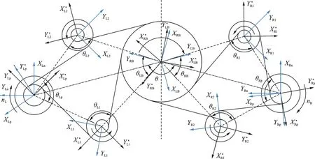
Fig.3 Relationship of partial and generalized coordinates of system

2.2 Force analysis of transmission system
Define that Finm2n,Finpjsand FinB2hare the meshing forces between gear pairs in the power input,split torque and the power confluence stage,respectively.Therefore,we have

where ribp,rib1s,rib2s,rib1h,rib2h,and rbBare the base radius of Zip,Zi1s,Zi2s,Zi1h,Zi2h,and ZB,respectively;ripmand ripnthe meshing radius of Zimand Zin,respectively. PXmn,PYmn,and PZmnthe calculation coefficients,which could be obtained by Eq.(4).

where αinis the normal pressure angle of Zin;βinthe helix angle;and δinthe cone angle of Zin. Suppose that finpjsand finBjhare the frictional forces in the gear pair of the split torque and power confluence stage,thus
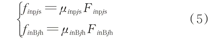
where μinpjsand μinBjhare the time-varying friction coefficients between gear pairs of the split torque and power confluence stage. The friction coefficient between the meshing surfaces is difficult to calculate accurately,because it is influenced by the meshing state,geometric parameters,microstructure of the tooth surface and the system conditions and lubrication. The calculation model of friction coefficient between the meshing surfaces is:Coulomb friction model,Buckingham empirical formula,Benedict &Kelly calculation model and elastohydrodynamic lubrication(EHL)friction coefficient calculation theory. The research result[21]shows that the friction coefficient calculated by EHL theory is closer to the experimental value. Therefore,the friction coefficient calculation model based on EHL theory is adopted in this paper. The friction coefficient can be expressed as

where ν0is the dynamic viscosity of the lubricating oil;Phthe maximum Hertz contact stress;Ve,SR and R are the entrainment velocity,slide-roll ratios and comprehensive curvature radius at the contact point of meshing tooth surface,respectively;S is the root mean square of tooth flank roughness;b1—b9is the empirical parameter,as shown in Table 1.

Table 1 Empirical parameters of EHL
The meshing forces and frictional forces of the gear pairs in the input stage,the split stage and the power confluence stage are decomposed and combined along the generalized coordinate system,and the resultant force in the generalized coordinate system direction is

2.3 Dynamic equation of transmission system
Fig.1 shows two sub-transmission system’s input torque TRDand TLD,along with the load To. According to Newton’s law,torsional vibration and axial vibration differential equations in the transmission system can be derived,as is shown in Eqs.(8),(9),respectively.


where rrijp,rrijs,rrijh,and rrijBare friction forces finpjson gear Zip,finpjson gear Zijs,finBjhon gear Zijh,finBjhon gear ZB.

In order to eliminate the displacement of the rigid body,the relative displacement of the gear meshing line and the torsional line displacement of the shaft are shown in Eqs.(10),(11),respectively.

where riDm,rinp,ri1s1h,ri2s2h,and rBoare the equivalent radius of the input shaft,the split shaft,the duplicate gear shaft 1,the duplicate gear shaft 2 and the output shaft,respectively.
The torsional displacement of the meshing gear pairs ZRpand ZR1sis converted into a line displacement along the meshing line by combining Eqs.(8),(10)and(11),and the differential equation of the meshing line is
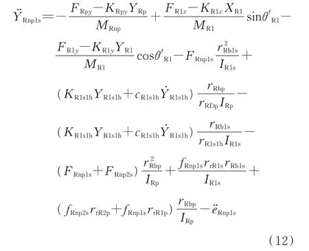
where MR1=mR1h+mR1s. Similarly,the differential equations on the other gear pairs meshing lines could also be obtained.
Based on Eqs.(8)and(11),the torsional displacement of the right branch duplicate gear shaft 1 is converted into linear displacement,thus vibration differential equation of torsional line displacementis
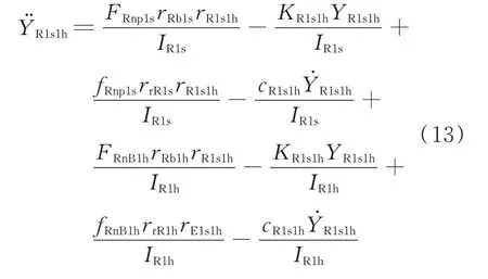
Similarly,differential equations of the torsional line displacement vibration of the other shafts could be obtained.
Based on the analysis above,the dynamic differential equations of the transmission system with only line displacement could be derived.
3 Friction Coefficient of Tooth Surface
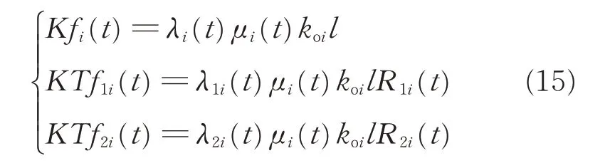
The frictional force and friction torque between the meshing surfaces are related to the factors such as friction coefficient,meshing stiffness,friction arm and so on. Friction coefficient,meshing stiffness and friction arm are all time-dependent periodic functions. In order to facilitate the subsequent calculation and analysis,the product of the time-varying friction coefficient and the time - varying meshing stiffness is defined as the friction stiffness Kf of the gear pair. The product of the time-varying friction stiffness and the friction arm is defined as the friction torque coefficient KTf of the gear pair

where λKf(t) is the friction direction coefficient,when the meshing point passes through the pitch point,the direction changes;and r(t) the friction arm.
3.1 Friction stiffness and friction torque of spur gear
The spur gear meshing schematic diagram is shown in Fig.4. For the spur gear transmission system,the length of the contact line KK' is constant and parallel to the axis from entering the mesh to exiting mesh. In a meshing cycle,the time-varying friction stiffness Kfi(t),the friction torque coefficients KTf1i(t) and KTf2i(t) of the contact tooth pair i can be expressed as

Fig.4 Engagement process of spur gear
where koiis the meshing stiffness of the contact line,and l the length of contact line. The total frictional stiffness and the total frictional torque coefficient of the spur gear pair in a meshing cycle are obtained by superimposing all the teeth in a meshing cycle.
The calculation results of the friction stiffness and torque coefficient of spur gear are shown in Figs.5,6. It can be seen that the direction of relative sliding speed between the contact flank changes,and as the meshing point moves away from the pitch point,the relative sliding speed and coefficient of friction increase. Hence,the frictional stiffness changes like them. In addition,the friction torque of the driving gear is the same as the direction of the driving torque. For the driven gear,during the meshing process from the entering point to the pitch point,the friction torque is the same as the load torque. However,when the meshing point passes through the node,the conclusion is reversed.
3.2 Friction stiffness and friction torque of herringbone gear

Fig.5 Friction stiffness of spur gear
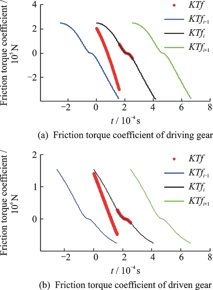
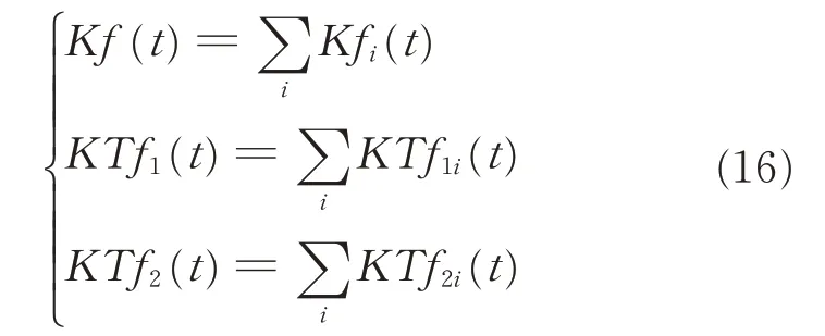
Fig.6 Friction torque coefficient of spur gear
Herringbone gear can be considered as double helical gears. Engagement process of helical gear is shown in Fig.7. The length of the contact line KK'gradually increases from zero to peak then decreases to zero during the mesh. If one tooth of the gear pair is divided into n pieces of unit length in the direction of the tooth width,each piece can be regarded as a pair of spur gears. At time t,the frictional stiffness Kfi(t,j) and the friction torque coefficients KTf1i(t,j),KTf2i(t,j) of the jth piece can be expressed as where dl is the unit contact line length. At that specific moment,the friction stiffness and the friction torque coefficient of the tooth i are


Fig.7 Engagement process of helical gear
where m is the number of pieces involved in the mesh at that moment. Substituting Eq.(18)into Eq.(16),the total friction stiffness and the total friction torque coefficient of the helical gear pair in a meshing cycle can be obtained.
Figs.8,9 are the curves of the friction stiffness and the friction torque coefficient of the herringbone gear. Their variation law is the same,and the variation amplitude of the driven gear is larger than that of the driving gear. Compared with the spur gear transmission,the stiffness curve is continuous without abrupt changes and its direction is almost constant. Due to the symmetry of the double helical gear,the direction of the friction torque coefficient hardly changes,so the resultant force direction of the friction is unchanged,which plays an important role in improving the dynamic characteristics of the gear transmission system and the tooth surface wear.
4 Analysis and Discussion

Fig.8 Friction stiffness of herringbone gear

Fig.9 Friction torque coefficient of herringbone gear
According to the transmission power and speed of an aviation reducer,the design parameters of the reducer are optimized,which are shown in Table 2.Since the dynamic equations are complex and the degrees of freedom involved is large,it is difficult to solve the dynamic equations by analytical method and numerical integration method. Therefore,the Fourier series method is used to solve the dynamic characteristics of the transmission system. In order to investigate the effect of tooth surface roughness on the dynamic characteristics of the system,the mean square root of the tooth roughness is set as 0.3,0.6 and 0.9 μm,respectively.
4.1 Tooth surface dynamic friction
Fig.10 is the time-domain response map of tooth surface dynamic friction. It can be seen that the dynamic friction of the system has periodic fluctuation,and tooth surface friction of herringbone gear is more stable than spur gear.
During the meshing process,the direction of spur gear’s tooth surface friction is changed,however,that of herringbone gear is unchanged. We compared tooth surface friction absolute value in three different kinds of roughness and found that the friction increases with the rise of the mean square root of the roughness,the friction coefficient is larger when the roughness is larger. For the spur gear meshing process,when the pair of teeth enter and exit meshing,the change in the number of teeth causes a sudden change in the meshing force of thetooth surface,resulting in the amplitude of tooth surface frictional reaching the maximum. Since the tooth surface friction factor at the time of entering mesh is greater than that of exiting mesh,resulting in greater frictional force,the magnitude of the absolute value of the frictional force is greater when the gear teeth enter the mesh. For herringbone gear,since the contact ratio of the double helical gear pair
is large and the gears in the mesh is more,plus,the directionality of the tooth friction makes the frictional force partially offset,the herringbone gears are vibrated smoothly and the amplitudes are much smaller than that of spur gears.

Table 2 Main parameters of the transmission system
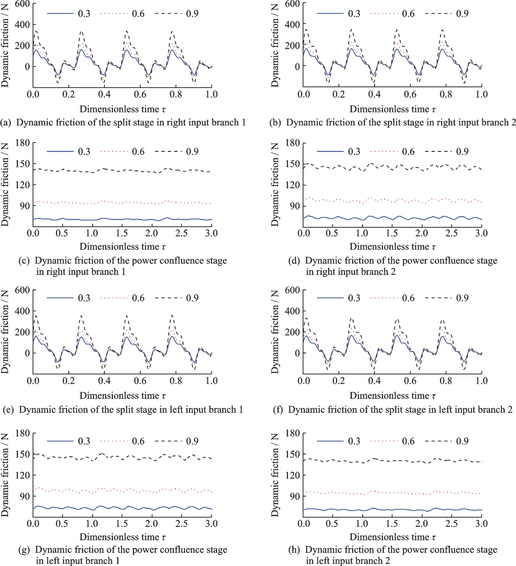
Fig.10 Time-domain image of the vibration response of friction force
There is a certain relationship between roughness and friction coefficients,but how to choose roughness is complicated because it involves many factors,such as material properties,surface structure,oil film and so on. In general,in an oil-lubricated environment,it is not as small as possible,as it involves at least the oil film. Therefore,there is a balance value,and it is necessary to test and explore specific friction pairs.
4.2 Dynamic meshing force of tooth pair
Fig.11 is the time-domain diagram of the dynamic meshing force between gear pairs. It can be seen that there is periodic fluctuation of dynamic meshing force in each branch,and the vibration amplitude of the herringbone gear is relatively smaller.

Fig.11 Time-domain image of the vibration response of meshing force
As can be seen from Figs.11(a),(b),(e)and(f),for spur gear,there is a noticeable meshing impact due to abrupt changes in the number of gears participating in the mesh. When the teeth are engaged,the direction of the friction torque is opposite to that of the driving gear torque,thereby suppressing the generation of the meshing force. During exit meshing,the direction of the frictional torque is the same as that of the driving gear torque,thereby increasing the meshing force. As the surface roughness of the tooth increases,the dynamic meshing force increases when the gear enters the mesh,and the meshing force at the time of exit is reduced. It can be seen from Figs.11(c),(d),(g)and(h)that for herringbone gear,due to the small change in the meshing stiffness of double helical gears,the dynamic meshing force response in the power confluence stage is stable and the vibration amplitude is smaller than that of the spur gear. Besides,for the closed force system of the transmission structure,the asymmetry of the force is caused by the structure itself,and amplified by the contact ratio,so the herringbone gears teeth dynamic meshing forces of power confluence stages in the left and the right branches have significant differences.
4.3 Bearing dynamic supporting force
Fig.12 is the bearing force of the time-domain signal and frequency-domain signal. From the timedomain signals in Figs.12(a)—(f),it can be seen that the roughness has little effect on the vibration amplitude of each split-torque and duplicate gear shaft bearing,but has some influence on the local vibration characteristics. Generally,the impact of the natural frequency of the power confluence stage is greater. It is clear that the effect on the bearing force vibration is mainly the first-order natural frequency of the split stage and the power confluence stage,and with the increase of the roughness,the influence of the split stage is increasing and that of the power confluence stage is decreasing. From the time-domain signal of Fig.12(g),it can be seen that the vibration of the output shaft bearing force is complicated,and the vibration amplitude and the fluctuation of the output shaft bearing force increase with the rise of the tooth surface roughness. As can be seen from the frequency-domain signal,the increment is the first-order response,while changes of the other orders are not obvious.


Fig.12 Time-domain and frequency-domain images of the vibration response of bearing force
5 Conclusions
(1)The product of time-varying friction coefficient and time-varying meshing stiffness is defined as the friction stiffness of gear pair. The product of time-varying friction stiffness and friction arm is defined as the friction torque coefficient of gear pair,and spur gear and helical gear’s friction stiffness and friction torque coefficient equations are derived.
(2)Taking multiple factors such as time-varying friction coefficient,time-varying meshing stiffness,support stiffness,torsional stiffness and comprehensive error into account,the dynamic equations of the double-input split torque transmission system with bending-torsional coupling is established.
(3)The friction stiffness curve of the herringbone gear is more stable and the amplitude of the frictional stiffness is smaller. Compared with spur gear’s friction stiffness curve,herringbone gear’s curve is continuously changed without any mutation,and the direction of friction stiffness is unchanged. Therefore,during the meshing process,the direction of the tooth surface friction of the spur gear is changed,and that of herringbone gear is unchanged.
(4)The friction force of herringbone gear is more stable than the spur gear,and the fluctuation is much smaller than spur gear. The meshing force of the spur gear is larger when entering mesh due to the directionality of the tooth friction force. The change of the meshing stiffness of herringbone gear is small,so the dynamic meshing force changes smoothly and the vibration amplitude is small. The amplitude of the bearing vibration is not obviously affected by the friction,but the friction has a certain influence on the bearing force of the output shaft.The effect on the bearing force vibration is mainly the first-order natural frequency of the split stage and the power confluence stage. Generally,the impact of the natural frequency of the power confluence stage is large.
AcknowledgementsThe work was supported by the National Natural Science Foundation of China (No.51475226).Meanwhile, the author would like to express sincere gratitude to the following people for their assistance: Zhu Rupeng, Fu Bibo, Yang Haoyun, and Chen Yuan, all with the National Key Laboratory of Science and Technology on Helicopter Transmission, Nanjing University of Aeronautics and Astronautics.
AuthorsDr. JIN Guanghu is a master’s supervisor at College of Mechanical and Electrical Engineering, Nanjing University of Aeronautics and Astronautics (NUAA). His main research interests include face gear drives, power split drive,gear dynamics and structural strength.
Mr. YANG Haoyun received his M.S. degree from NUAA,Nanjing, China, in 2016. His current research interests include gear design, gear dynamics and structural strength.
Dr. LU Fengxia is a master’s supervisor at College of Mechanical and Electrical Engineering, NUAA. Her main research interests include tribology, dynamics and lubrication of gear trains.
Prof. ZHU Rupeng is a doctoral supervisor at College of Mechanical and Electrical Engineering, NUAA. His main research interests include new driving technology, microstructure design, fretting friction, and shaft-gear transmission system dynamics.
Author contributionDr. JIN Guanghu designed the study, interpreted the results and wrote the manuscript. Mr.
YANG Haoyun contributed to the programming calculation and discussion. Dr. LU Fengxia contributed to the discussion and translation proofreading. Prof. ZHU Rupeng contributed to the discussion and background of the study. All authors commented on the manuscript draft and approved the submission.
Competing interestsThe authors declare no competing interests.
杂志排行
Transactions of Nanjing University of Aeronautics and Astronautics的其它文章
- Recent Advances in Hole Making of FRP/Metal Stacks:A Review
- Parameter Optimization for Improvement in Biomachining Performance
- Mathematical Model and Machining Method for Spiral Flute Rake Faces of Hourglass Worm Gear Hob
- Active Design Method of Tooth Profiles for Cycloid Drive Based on Meshing Efficiency
- Design and Study of Virtual Interventional Surgical System with Force Feedback
- Remaining Useful Life Prediction of Rolling Element Bearings Based on Different Degradation Stages and Particle Filter