Active Design Method of Tooth Profiles for Cycloid Drive Based on Meshing Efficiency
2019-08-01WANGJianSUDeyu
WANG Jian,SU Deyu
1.School of Mechanical Engineering,Nanjing Institute of Technology,Nanjing 211167,P.R.China;
2.Institute of Intelligent Manufacturing,Huazhong University of Science and Technology in Quanzhou,Quanzhou 362300,P.R.China
Abstract: An active design method of tooth profiles for cycloid gears based on their meshing efficiency is proposed.This method takes the meshing efficiency as one of the design variables to determine the tooth profiles. The calculation method for the meshing efficiency of planetary transmission is analyzed and the equation of the meshing efficiency is deduced. Relationships between the meshing efficiency,the radius of the pin wheel and the eccentric distance are revealed. The design constraint quations and the strength constraint quations are deduced. On the basis of this,a design procedure is laid out. Some examples using different input parameters are conducted to demonstrate the feasibility of the approach. A dynamic simulation of the rigid-flexible coupling of cycloid gears is also presented. The results show that the proposed design method is more flexible to control the tooth profiles by changing the input values of the transmission efficiency.
Key words: cycloid drive;tooth profile;active design;meshing efficiency;meshing theory
0 Introduction
There are two methods in gear design. One is a rack-based design method,the other is the direct or active design method. The more commonly used is the former,largely due to its greater simplicity across design,manufacturing and stress analysis. It also holds easier interchangeability. However,this method only has one parameter,the addendum modification,that can be used to change the geometry of the gears. Nowadays,a variety of different non-standard gears have been developed and utilized to fulfill different applications[1-5]. Gears have become popular,but not interchangeable,for different applications. It is obvious that a rack-based design method imposes its own nature limits on gear performance improvements[6-7].
Many issues have been addressed in the direct or active design method for non-standard gear tooth profiles. Fong et al.[8]put forward a mathematical model of tooth profiles for spur gears that was based on a given line of action. To demonstrate the approach,an example gear drive that took a combinative curve as its line of action was developed. Danieli et al.[9]proposed a new method in which the pressure angle for any given tooth had a constant value,whilst the radius could vary. The results showed that it was able to increase a gear drive’s contact ratio. Wang et al.[10]developed a method that was able to synthesize the tooth surfaces of a face-milled spiral bevel gear set according to a predetermined transmission error,which was a fourth-order polynomial function. Lee[11]reported a new cylindrical crown gear drive that was based on transmission error as well,and used a controllable fourth-order polynomial function. Shih[12]proposed a new ease-off method for the flank modification of face-hobbed and facemilled hypoid gears using a cartesian-type hypoid gear generator. Kapelevich et al.[6,13],meanwhile,developed a direct gear design method. The performance of gears designed by this method was treated as something separated from tool selection. These kinds of gears were particularly well-suited to certain applications,notably in aerospace and the automotive industries. Muni et al.[14]adopted a direct gear design approach,in their case to establish an optimal methodology for designing asymmetric spur gears that could maximize their bending strength.Sekar et al.[7]added the notion of an“area of existence”to the direct gear design method. This was used to work out the load sharing ratio between simultaneously loaded contact pairs in asymmetric helical gear drives. It also enabled them to calculate the relative values for non-dimensional stress. Tang et al.[15]introduced an improved active design method for spiral bevel gears that was based on a given transmission error,taking the form of a parabolic function. By controlling contact path and transmission errors,Cao et al.[16]proposed a new approach to design pinion machine tool-settings for spiral bevel gears. Lastly,Wang et al.[17]used an active design method to establish the pressure angle function for high contact ratio spur gears. In this case,the results confirmed that gears designed using this method could satisfy different contact ratio requirements and produce generally better transmission characteristics.
Cycloid gears are widely used in many fields,such as machinery,robotics,metallurgy,etc.,because of their compactness,large gear ratio,heavy overload capacity,and lighter weight[18]. In recent years,a number of studies have attempted to improve the meshing efficiency of gear drives so as to reduce power loss,wear and noise. Currently,the principal approach to calculating meshing efficiency is experimentation. However,significant differences exist between different kinds of data acquired in this way[19]. According to the grade of precision and kind of lubrication,the value of the meshing efficiency within a certain range was selected from a handbook,but the selection of the correct value in this way was far from straightforward[20]. Approaching things in this way was also likely to lead to significant errors for cycloid drives,especially multistage cycloid drives.
In order to improve the meshing efficiency of cycloid gear drives,we propose an active design method of tooth profiles for cycloid gear drive.
1 Method for Calculating Meshing Efficiency
This section presents a new methodology for calculating meshing efficiency and deriving the meshing efficiency function. As a systematic approach,it has the advantage of being easily implemented in a computer program.
1.1 Standard tooth profile equation for cycloid gears
In cycloid gear drives,the standard tooth profile conjugates with the pin wheel without clearance.Assume that zpdenotes the tooth number of the pin wheel,a the eccentric distance,and zcthe tooth number of the cycloid gear.The equation of the standard tooth profile for cycloid gears in a natural coordinate system can be expressed as[21]

where α is the rotation angle of the ith pin wheel relative to the tumbler OpOc;rrpthe radius of the pin wheel;K1the short width coefficient;Rpthe radius of the pin wheel’s central circle;and iHthe relative transmission ratio between the cycloid gear and the pin wheel,which can be expressed as iH=zp/zc.
1.2 Meshing efficiency
One of the key characteristics of a gear drive is its meshing efficiency. In this subsection,the equation of meshing efficiency for cycloid gear drives is deduced. Suppose that Ttand Tpdenote the input torque and the output torque,respectively;and ωtand ωpthe speed of the input shaft and the output shaft,respectively. The input power Wtcan be expressed as

The kinematical analysis shows that a sliding contact between the cycloid gear and the pin wheel occurs. The consequent power loss for a single pin wheel can be obtained by means of the equation Wf=μFiVri. According to Ref.[22],we suppose that the teeth numbered from m to n are in mesh simultaneously. The power lose Wfduring meshing for the two-cycloid gear structure can be expressed as

where Fidenotes the contact force between the ith pin wheel and the cycloid gear;Vrithe relative sliding speed;and μ the friction coefficient between the cycloid gear and the pin wheel.
The meshing efficiency η can defined by

Substituting Eqs.(2)and(3)into Eq.(4),the meshing efficiency η for a cycloid gear drive can be calculated as

2 Model for Active Design of Cycloid Gear Tooth Profiles Based on Meshing Efficiency
2.1 Relationship between meshing efficiency and eccentric distance
As shown in Fig.1,a torque Mcis applied into the cycloid gear. Suppose that pin wheels are stationary,in a theoretical case,all teeth of the cycloid gear are in contact with the corresponding pin wheels and half of them transfer load. In a theoretical case,all teeth of the cycloid gear are in contact with the corresponding pin wheels and half of them transfer load. According to gear meshing theory,the maximum load Fmaxfalls on the pin wheel,where the maximum number of arms is lmax=Rc(Rcdenotes the pitch radius of the cycloid gear). The torques on two cycloid gears are usually unequal because of errors in manufacturing. One of the torques Tccan therefore be taken to be larger than 0.5Tp,where Tpis the total torque delivered by the output shaft. According to Ref.[23],let Tc=0.55Tp. The force Fion the ith pin wheel and the maximum meshing force Fmaxcan then be expressed as

where liis the distance between the center Ocof the cycloid gear and the normal line of the contact point of the ith pin wheel.
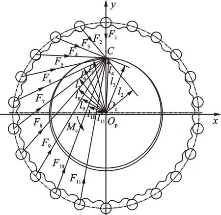
Fig.1 Meshing force of cycloid drive
Fig.2 shows the ralative speed of a cycloid gear drive has no pin gear sleeves. In Fig.2,γ is the meshing angle of the ith pin wheel;B1the center of the pin wheel;B2the meshing point between the cycloid gear and the pin wheel,and P the instantaneous center. Drawing a perpendicular line from point B1to POc,the intersection point will be B3.According to Fig.2,we have

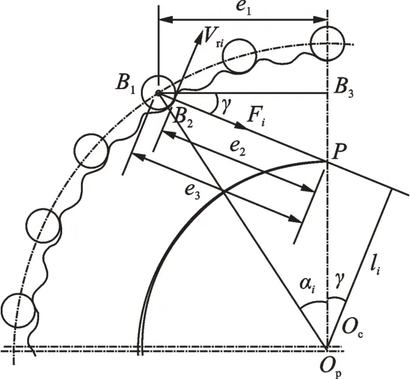
Fig.2 Relative sliding speed
The relative sliding speed Vrican now be determined using the following equation

Substituting Eqs.(6)and(9)into Eq.(3)yields

Using the definition of the definite integral,Eq.(10)can be rewritten as

By integrating Eq.(11),Wfcan be derived as

Substituting Eqs.(2)and(12)into Eq.(4),the meshing efficiency η can be expressed as

Supposing that the range of the meshing efficiency η is[b1,b2],the range of the eccentric distance a can be expressed as

2.2 Limitations
In this subsection,The design constraint quations including the curvature radius,the short width coefficient and the coefficient of the gear pin diameter are deduced. The strength constraint quations including the contact strength of cycloid gear,the bending strength of pin wheel,the bending strength of pin are also built in this subsection.
2.2.1 Curvature radius
According to Ref.[24],the theoretical value ρ0and actual value ρ of the curvature radius for cycloid tooth profiles can be expressed,respectively,as follows

If ρ0<0,the shape of the curve is concave;if ρ0>0,the shape is convex.
For outer convex tooth profiles,when rrp>|ρ0|,the equidistant curve for the tooth profile cannot be realized(the equidistant curve has a crossover tooth profile). As a part of the effort to get an efficient profile,over-cutting can appear during the manufacturing process.This phenomenon is called cutting interference and it is able to destroy stable meshing. If rrp=|ρ0|,ρ=0 and the tooth profile will have a sharp corner,which can also impact upon the meshing.As ρ0is a positive value,no matter what value is given to rrp,the phenomenon of cutting interference will not appear. For cycloid tooth profiles with the outer convex addendum,functions of the minimum curvature radiuscan be expressed as
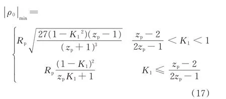
The condition for avoiding cutting interference or sharp corners for tooth profiles can thus be represented as

2.2.2 Short width coefficient
According to Ref.[21],the formula for calculating the short width coefficient K1can be expressed as

The value of K1is close to the tooth profile for cycloid gears and influences the transmission performance of the drive. It makes the short width coefficient K1a significant parameter that must not be too large or too small. In this section,we shall examine each of those two possibilities separately.
(1)Ensuring that K1is not too large
If K1is too large,the outer convex portion of the tooth profile will be considerably larger than the inner concave portion and |ρ0/Rp| for the outer convex portion will also be relatively small. In addition,the value of rrpwill be smaller with regard to rrp<|ρ0|min,making the working contact stress much larger. Furthermore,when K1is too big and the transmission ratio is consequently smaller,the eccentric distance a=K1Rp/zpbecomes too large as well,leading to a difficult design of W.
(2)Ensuring that K1is not too small
If K1is too small,the pitch radius of the cycloid gear and the pin wheel will decrease. The distance between the center of the cycloid gear Ocand the pitch point P will also decrease. Under certain torque conditions,the meshing force between the cycloid gear and the pin wheel will become larger as the arm OcP is decreased. The recommended values for the short width coefficient K1are listed in Table 1.

Table 1 Recommended values for the curtate ratio K1[24]
2.2.3 Coefficient of gear pin diameter K2
The coefficient of the gear pin diameter measures the distribution density of pin wheels. As shown in Fig.3,when choosing the radius of the pin wheels,one need to avoid pin wheel collisions and guarantee the integrity of the pin wheels and pin gear housing. It is best to choose values for the coefficient of the gear pin diameter where K2=1―4 or K2=1.5―2. When zp≥44,the coefficient of the gear pin diameter should be selected to be K2≥0.99―1.0 in order to avoid collision. The reference values for K2are shown in Table 2. The relationship between the radius of pin wheel rrpand pin-diameter coefficient K2can be expressed as
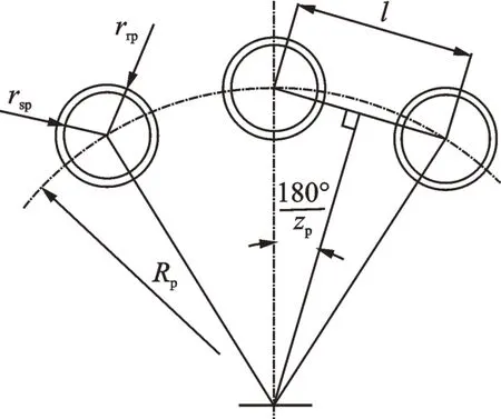
Fig.3 Coefficient of gear pin diameter K2


Table 2 Recommended values for K2[24]
2.2.4 Contact strength of cycloid gear
According to Ref.[24],using Hertz theory,the contact stress between the pin gear and cycloid gear can be expressed as
where Eeis the equivalent elastic modulus;B the width of the cycloid gear;ρeithe equivalent curvature radius;and σHPthe allowable contact stress.
Supposing that σHmaxrepresents the maximum contact stress,according to Eq.(21),one can define

where ρeminreperesents the minimum equivalent curvature radius;Fmaxthe maximum meshing force between the pin gear and cycloid gear. In order to shorten the running time,Fmaxcan be calculated using the following equation[24]


where Tpis torque of the output shaft,and can be calculated as where n is the input speed and η the meshing efficiency for cycloid gear drives.
Hence,Eq.(22)can be rewritten as

The constraint equation can be finally defined by

2.2.5 Bending strength of pin wheel
During the meshing period,the meshing force between cycloid gear and pin wheel will cause bending deformation of pin wheel. The excessive bending deformation will certainly lead to bad contact,which will make it easier for veneering failure either between cycloid gear and pin wheel. Therefore,it is necessary to check the bending strength of pin wheel.
Generally,when Dp<390 mm,pin wheel with two pivots is used;otherwise,pin wheel with three pivots is used. According to Ref.[24],as for pin wheel with two pivots,the bending stress of pin wheel can be expressed as

where L denotes the span of pin wheel.
As for pin wheel with three pivots,the bending stress can be expressed as follows

Hence,the constraint equation can be finally defined by

2.2.6 Bending strength of pin
The bending strength of pin can be expressed as[24]

where Δcis the thickness of the space ring;Kwthe influence coefficient of manufacturing error and installation error on load of pin;dswthe diameter of pin,and σBPthe allowable bending stress. For simple applications,the suggested value of Kwis 1.4.
The constraint equation can be defined by

where Dwrepresents the diameter of pin central circle and zwthe number of pins.
2.2.7 Constraint functions
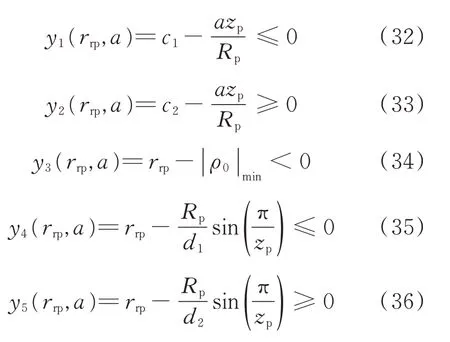
Assume that the range of K1is[c1,c2]and the range of K2is[d1,d2],the design constraint equations can be used for design, as listed from Eq.(32)to Eq.(36),while Eqs.(26),(29)and(31)the strength constraint equations,can be used for check.
3 Design Procedure
The mathematical model for the active design of cycloid gear tooth profiles based on meshing efficiency is built in Section 2. Based on this model,a computer simulation process is developed to plot the tooth profiles of the gears,and to analyze the characteristics of the gear drive. The design method of the tooth profile in this paper is broken down into four steps as shown in Fig.4.
Step 1 Set basic design parameters,including the radius of the center circle Rp,the number of teeth zcof cycloid gear,transmission ratio i,width of cycloid gear B,the diameter of pin central circle Dw,the number of pins zwand the diameter of pin dsw.
Step 2 Assign the required value of the meshing efficiency for the cycloid drive. The range of the eccentric distance a is then obtained based on Eq.(14). Choose a within the range obtained in Step 2.
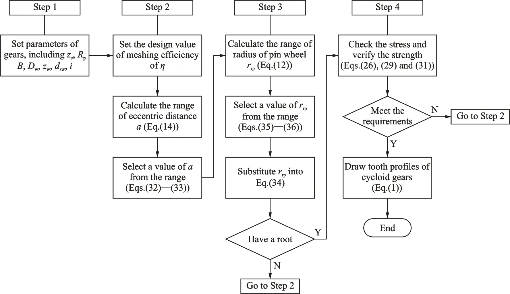
Fig.4 Flow chart for active design procedure
Step 3 Calculate the range of radius of pin wheel rrpbased on Eq.(12)and choose rrpwithin the range according to Eqs.(35)and(36). Substitute rrpinto Eq.(34),the solution existence condition can be checked. If the profile has no solution at this stage,it will be necessary to go back to Step 2.Otherwise,go to Step 4.
Step 4 Determine whether the strength can meet the requirements according to Eqs.(26),(29)and(31). If one of the stresses cannot meet the requirements,it will be necessary to go back to Step 2. Otherwise,the choices can be considered to be reasonable. Once the solution is established,the above parameters can be applied to Eq.(1). The tooth profile for the cycloid gear can now be drawn.
4 Examples
In this section,tooth profiles with different input parameters are established by examples in order to demonstrate the feasibility of the proposed methodology. GCr15 material is selected for cycloid gear,pin wheel,pin and pin sleeve of cycloid speed reducer for those. The values of the contact and bending stresses are σHP=1 000 MPa, σFP=200 MPa and σBP=200 MPa,respectively. The equivalent elastic modulus is Ee= 2.06×10⁵MPa,the input speed is n=1 440 r/min,the input power is Wt=0.75 kW,the friction coefficient is μ =0.05,and the thickness of the space ring is Δc=4 mm,the span of pin wheel is L=40 mm. Other chosen constant parameters are as follows:the transmission ratio for the cycloid drive is i=43,the number of teeth for the cycloid gear is zc=43,the radius of the center circle is Rp=72.5 mm,the width of the cycloid gear is B=11 mm,the diameter of pin central circle is Dw=90 mm,the number of pins is zw=8,the diameter of pin is dsw=12 mm.
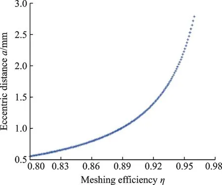
Fig.5 Relationship between meshing efficiency and eccentric distance
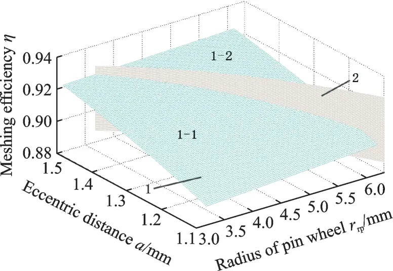
Fig.6 Mathematical model for active design of meshing efficiency
As shown in Fig.5,when the variable parameters for meshing efficiency are used,the eccentric distance a becomes greater as the meshing efficiency increases. As shown in Fig.6,if only the short width coefficient K1is considered(Eqs.(32)and(33)),Surface 1 will denote the relationship between meshing efficiency and the other two parameters(the radius of the pin wheel and the eccentric distance). Surface 2,which divides Surface 1 into Surface 1-1 and Surface 1-2 ,represents the limited surface for the minimum curvature radius(Eq.(34)). To avoid any cutting interference or sharp corners,a and rrpneed to be chosen on Surface 1-1. When considering the coefficient of the gear pin diameter K2(Eqs.(35)and(36)),the range of the pin wheel radius is[3.232,5.172].
In Table 3,the cycloid gear is designed to have a pin wheel radius of rrp=4 and the meshing efficiency varies from 0.9 to 0.92. The contact strength of cycloid gear σHmax,the bending strength of pin wheel σFand the bending strength of pin σware also calculated,as shown in Table 3. These valus are all smller than allowable values. By using Matlab,the tooth profiles of cycloid gear are plotted in Fig.7 according to the proposed design method. In Table 4,the meshing efficiency η=0.91 is a constant value and the pin wheel radius varies from 3.5 to 5. Using the proposed method,the tooth profiles of cycloid gear are shown in Fig.8. In the fourth example in Table 4,the bending strength of pin wheel σF=228 MPa. It is higher than the allowable value 200 MPa.The initial parameters of the fourth example in Table 4 must be reselected according to Fig.4.
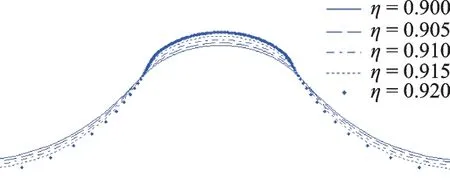
Fig.7 Tooth profile for parameters in Table 4
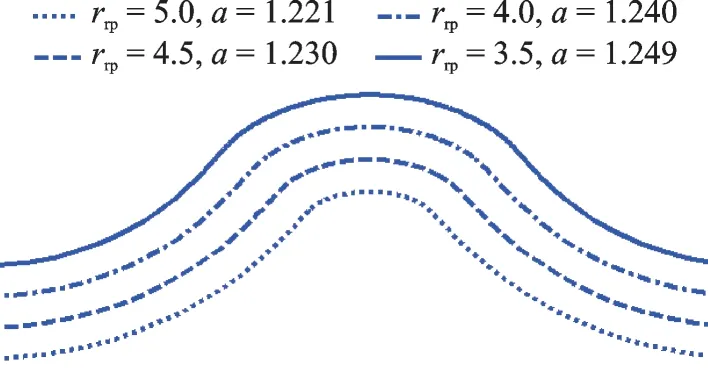
Fig.8 Tooth profile for parameters in Table 5

Table 3 Design parameters with the same pin wheel radius
Since Eq.(11) has an approximate integral form,it is necessary to verify the validity of the meshing efficiency by using Eq.(10). The values for the pin wheel radius and eccentric distances across four sets of examples are listed in Table 4. A meshing efficiency η=0.91 is selected as the initial value. Substituting the above parameters into Eq.(10),the friction power loss can be obtained.According to Eq.(5),the meshing efficiency for the four sets of examples can then be calculated. The errors compared with the initial meshing efficiency are also listed in Table 4. According to Table 4,the errors between the calculated meshing efficiency and the original meshing efficiency are within 4%. Thevalidity of the meshing efficiency equation is thus verified and the feasibility of using the proposed active method for cycloid drive design is proven.

Table 4 Design parameters with the same meshing efficiency
5 Discussions
In this section,a further investigation of the newly designed gears is conducted. A dynamic simulation of rigid-flexible coupling of cycloid gears is developed. The meshing force with friction is calculated and the meshing force according to the simulation is compared with the theoretical approach.
The three-dimensional models of the pin wheel and the cycloid gear have been developed by Pro/E and then transferred to ANSYS. In ANSYS,the properties of the materials are set as follows:The poisson ratio is 0.3 and the density is 7.85×10⁻⁶kg/mm3. The model is built using 8-node Solid 185 elements. Other parameters are shown in Table 5. The external nodes of the two inner bores are defined so as to establish the kinematic pair or load point,as shown in Fig.9. In Fig.9,nodes in the center of the hole are defined as external nodes. Nodes in the corresponding inner surface of the hole and those external nodes are coupled to establish rigid region. The same method is also applied to the pin wheel. In ADAMS,the parameters are set as:Damping coefficient C=50 N/(mm·s-1),k=1×105N/mm,d=0.1 mm,and e=1.5. The simulation time is 1 s and the step size is 100.
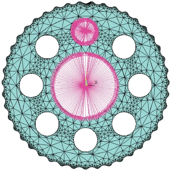
Fig.9 Flexible model of cycloid gear
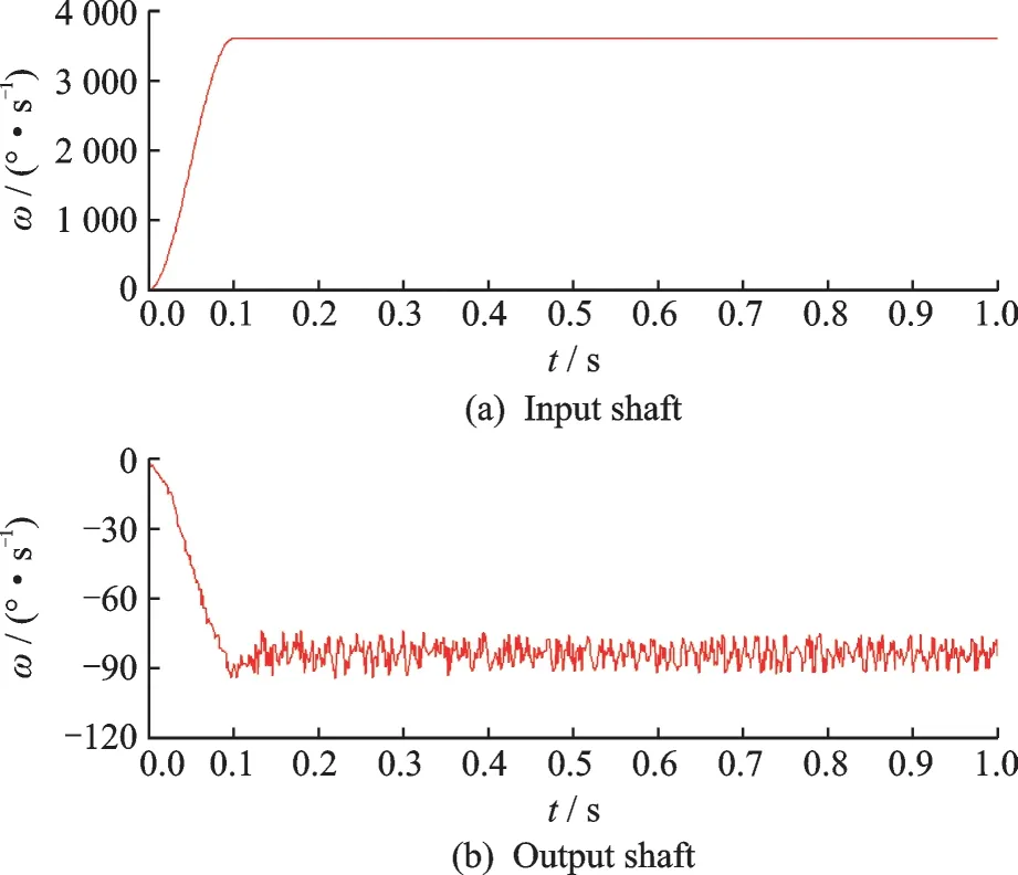
Fig.10 Angular speed of input shaft and output shaft
Figs.10(a),(b)show the angular speed for the input shaft and the output shaft,respectively.Fig.11 represents the meshing forces between the pin wheel and the cycloid gear according to different parameters. The theoretical results and the simulation results of meshing forces are listed in Table 5.From Figs.10,11 and Table 5,the following conclusions can be drawn:(1)The angular speed for the input shaft is 3 600 °/s,and the transmission ratio is 43,then the theoretical result of angular speed of the output shaft can be calculated as 83.72 °/s.Over the time period from 0.1 s to 1 s,the simulation result of the average angular speed of the output shaft is 83.91 °/s. The relative error between the theoretical result and the simulation result is about 0.23%. It is confirmed that the simulation method is adequate.(2)The meshing forces of the simulation results are at least 11% higher than that of the theoretical results. It can provide theoretical basis and technical support for engineering.

Fig.11 Meshing force between pin wheel and teeth

Table 5 Results of meshing forces
6 Conclusions
An active method for designing cycloid gear profiles based on meshing efficiency is presented.The principal design idea is to control the shape of the tooth profile by specifying the range of the meshing efficiency. In other words,the meshing efficiency,which is typically taken as a performance measure,is directly used as a design variable to determine the tooth profiles. It is an effective method for deducing the shape of the tooth profiles according to the quality of their performance. In this approach,the required performance is given in advance,rather than choosing different tooth profiles to obtain a good performance. The results show that gear sets designed using the proposed method will more easily achieve required levels of performance than comparable conventional design methods. As technology continues to develop,the demand for cycloid drives with high meshing efficiency will continue to grow across a range of possible applications. The cycloid gears designed by using the proposed method have shown some interesting properties,which will need to be further examined.
AcknowledgementsThe work was supported by the National Natural Science Foundation of China (Nos.51205335,51375411) and the Scientific Research for the High Level Talent of Nanjing Institute of Technology (No.YKJ201702).
AuthorsDr. WANG Jian received his B.S. degree in mechanical engineering from Hunan University of Science and Technology in 2004 and Ph.D. degree in mechanical engineering from Xiamen University in 2013. Now, he is an associate professor in Nanjing Institute of Technology. His research is focused on mechanical transmission.
Mr. SU Deyu received his B.S. degree in mechanical engineering from Hunan University of Science and Technology in 2015. Now, he is an engineer in Institute of Intelligent Manufacturing of Huazhong University of Science and Technology in Quanzhou. His research is focused on mechanical transmission.
Author contributionsDr. WANG Jian proposed the design method, conducted the analysis and wrote the manuscript. Mr. SU Deyu contributed to the discussion and background of the study.
Competing interestsThe authors declare no competing interests.
杂志排行
Transactions of Nanjing University of Aeronautics and Astronautics的其它文章
- Recent Advances in Hole Making of FRP/Metal Stacks:A Review
- Parameter Optimization for Improvement in Biomachining Performance
- Effect of Friction on Dynamic Response of A Power Split Transmission System
- Mathematical Model and Machining Method for Spiral Flute Rake Faces of Hourglass Worm Gear Hob
- Design and Study of Virtual Interventional Surgical System with Force Feedback
- Remaining Useful Life Prediction of Rolling Element Bearings Based on Different Degradation Stages and Particle Filter
