Research on Prepreg Tape Cutting Platform with Two Cutters
2019-08-01WENLiweiHUANGXiaochuanQINLihuaWANGXianfengLIYong
WEN Liwei,HUANG Xiaochuan,QIN Lihua,WANG Xianfeng,LI Yong
College of Materials Science and Technology,Nanjing University of Aeronautics and Astronautics,
Nanjing 211106,P.R.China
Abstract: The concept of cutting platform is proposed and realized based on the latest two-step automated tape laying(Two-step ATL)technology,which separates prepreg cutting process from tape laying to improve productivity for large parts with small features. Two-step ATL is more efficient than conventional layup because ply patches are pre-cut in a separate operation. The concept of the prepreg tape cutting experimental platform with two cutters is introduced. Further,based on the automatic tape laying trajectory planning software,a two-cutter cutting algorithm is proposed.Cutting experiments are reported to validate both the concept of cutting platform and cutting algorithm.
Key words: two-step automated tape laying (Two-step ATL); cutting platform with two cutters; cutting algorithm;cutter distribution
0 Introduction
Automated tape laying (ATL) can be considered as an additive manufacturing, which is widely used in the aerospace and renewable energy industries. Its advantages are high layup rates and capability to manufacture large parts[1]. Recent applications of ATL include wing skin of F-22 and C-17, stabilizer skin of Boeing 777 and A340, center wing box of A380 and so on[2-3]. ATL integrates the functions of cutting,locating,paving,compaction and so on[4]. Tapes are laid on the surface of the mould along a pre-defined trajectory and consolidated by a roller. Labor force and material waste rate are largely reduced. Compared with other process forms,ATL is overwhelming in quality, repeatability, accuracy and production efficiency[5].
In conventional single-phase ATL, tape cutting and laying are processed simultaneously. Some issues are existed in ATL,for example,it is unable to cut some specific boundary shape, and the cutting scrap cannot be eliminated in the process of laying[6]. In order to solve such problems, France Forest-Line developed a nesting technology for ATL layup in 1980s, often referred to as a two-step layup.
The original concept of two-step ATL is raised by the US and Japan[7-8]. But France Forest-Line developed the equipment first. Its two-step ATL equipment is composed of two parts. Advanced composite cassette edit/shear system(ACCESS)and automatic tape laying system(ATLAS). Ply patches are pre-cut, stored on a ply-backing and wound back onto a roll on the ACCESS system and then laying without cutting on the ATLAS.The machine of ACCESS has two ultrasonic cutters to handle complex boundary shape[9-10]. The process flowchart of Forest-Line two-step ATL is shown in Fig.1.
Domestic research on two-step ATL is still in its infancy stage. Compared with conventional ATL, tow-step ATL has the advantages as follows:
(1)Capablity of handling complex boundary shapes.
(2)The local reinforcement part that can be conducted in the main laying process.

Fig.1 Flowchart of Forest-line’s two-step ATL
(3)Reduction of 5%—10% in cutting scrap.
(4)Re-use of ACCESS machine for at least two ATLAS machines,which can improve productivity greatly[11].
Two-step ATL is a kind of rising technology with promising future. However,its development in China has been lagging behind the world level. In order to fill the gaps, a concept of cutting platform is proposed in this paper. As previous stated, pre-cutting is decisive in two-step ATL. Thus, a thorough study of boundary based cutting information generation method and experiments are presented.
1 Two-Cutter Prepreg Tape Cutting Platform Design
1.1 Design ideas
The principle and pr ocess of two-cutter tape cutting platform are shown in Fig.2.

Fig.2 Principle diagram map of prepreg cutting platform
Both sides of prepreg tape are protected by backing paper and isolation film.A spool unrolls prepreg before cutting. According to the cutting files,two cutters cut the tapes after they pass through the film separator[12]. After cutting and eliminating scraps,tapes with new film and paper are re-rolled up in the cassette.
The tape cutting platform has two ultrasonic cutters. Compared with one cutter, this platform is able to cut complex boudnary without revolving the prepreg spool. That is, the spool rotates continuously in the same direction, which improves cutting effecicy.
Three different boundary shapes are shown in Fig.3. Boundaries 1 and 3 can be cut by one cutter by changing the directions of prepreg spool;while,bounday 2 can only be cut by two cutters without revolving prepreg spool. In order to cut shapes similar to boundary 2, two cutters are used in tape cutting platform.
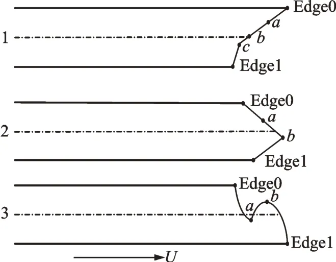
Fig.3 Different types of laying boundary
1.2 Overall design
Prepreg tape cutting platform is designed according to the existing motion axes on the splicing and rewinding machine which is owned by R & D Center for Composite Industry Automation,Nanjing University of Aeronautics and Astronautics(NUAA).
1.2.1 Design and control of prepreg spool
The mechanism of correct deviation is placed on the spool. When prepreg roller deviates from center position, a executing system pushes the roller back to rectify deviation. According to the length of each tape and different types of laying boundary,spool rotates and decides prepreg position. At the same time,the spool holds the prepreg tension in a proper range. Thus,encoders are attached to spool to ensure closed-loop control.
1.2.2 Design and control of film separator spool and paper separator spool
Film separator collects isolation films before cutting, which makes the prepreg easier to cut. Cutting scraps are remained on paper and eliminated after cutting by paper separator. For this reason,film separator spool and paper separator spool are controlled by torque motors. Torque motor provides constant torque opposites to the motion of prepreg tape,in order to maintain prepreg tension. The output torque of motor is monitored by magnetic particle clutch.
1.2.3 Design and control of two-cutter platform
The design principle diagram of prepreg tape two-cutter platform is shown in Fig.4.
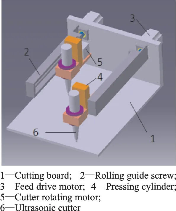
Fig.4 Design principle of two-cutter tape cutting platform
The platform consists of six parts, including cutting board,rolling guide screw,feed drive motor,pressing cylinder,cutter rotating motor, and ultrasonic cutter. Feed drive motor drives the rolling guide screw and guides the cutter set on them. Cutter rotating motor controls the angle of the cutter along the cutting direction all the time by trasmission belt which connects the motor and cutter tightly. Pressing cylinder moves the cutter up and down by an electromagnetic valve. The moving distance of pressing cylinder is controlled by a pole whose size is divided on it. Given that the thickness of the prepreg is 0.125 mm usually and minimum scale of that pole is 0.01 mm,positioning accuracy of the cutters is 0.01 mm. It is adjusted to make sure the cutter can cut the tape successfully. And the tape’s cutting is dependent on the vibration by ultrasonic cutters[13-14].
In summary,this platform has two feed drive motors and two cutting rotating motors owing to two cutters. After rotating motors drive the cutters at their certain angles,the prepreg is cut according to synchronizaion movement of prepreg spool axis and cutter feed axis.
1.3 Two-cutter tape cutting experimental platform building
According to previous states of cutter platform, the experimental platform of two-cutter tape cutting is shown in Fig.5.

Fig.5 Cutting experimental platform with two cutters
2 Cutting Algorithm
In this paper, cutting algorithm is based on trace file and boundary file,which are generated by ATL trajectory planning method[15].
In trace file, all track points are indentified, including track number,all the points(lying on the centre of w wide prepreg tape,w/2)coordinates(Cartesian coordinate)of one track and their normal vector.
Boundary file stores the information of mould boundary points,with fixed intervals. These points’coordinates are arranged clockwise from the start point of laying.
In cutting algorihtm, all the cutter’s control information is renerated. Algorithm flow is presented as follow.
2.1 Coordinate transformation
Both track points and normal vector coordinate points are built in Cartesian. It is hard to calculate cutting parameter directly. Coordinate transformation is necessary from the globe to the local coordinate system {E}[16]. Therefore,Cartesian X,Y,Z transforms to the local coordinate U,V,W by a homogeneous transformation matrix0
ET.
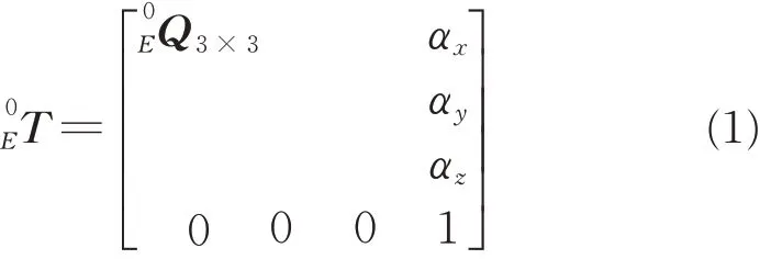
whereE0Q3×3is a rotation matrix;[αxαyαz]Ta translation matrix. The orientation of U goes along tape’s moving direction. Simultaneously,V is normal to U in the cutting plane. The orientation of cutters downing is U × V momently,as shown in Fig.6.

Fig.6 Coordinate transformation
As shown in Fig.7, S is the mold surfae,traj is one of the trajectories,and Pnis a dispersed points of this trajectory. The start point Pstartand end point Pendare mapped to P′startand P′endwhich are in the local coordinate system {E}. The mapped points are shown in Fig.8.

Fig.7 Mould boundary
Suppose a boundary point pi. Its Cartesian coordinate is [ xi,yi,zi],and its local coordinate is[ui,vi,0]according to Eq.(1).


Fig.8 Mould boundary mapping to{E}

All the points is mapped to the {E} from Cartesian by Eq.(3).
2.2 Key cutting points
There must exists boundary point Pnearthat is the nearest one to the start point Trajstartof track n on the disperse mould boundary,as shown in Fig.9.The first point is found whose distance from Trajstartis longer than w/2,Pstartand Pend. Then cutting points Edge0 and Edge1 are obtained whose distance from Trajstartis equal to w/2.
From Edge0 to Edge1,all the cutting points are key. Similarly,points Edge0′ and Edge1′ which are key cutting points on the end of track can be obtained in the same way.

Fig.9 Sketch of laying trajectory and mould boundaries
Suppose P′iand P′i+1are already mapped adjacent points. The length of tape moving ΔU and the distance of cutter moving ΔV are shown in Fig.10.

Fig.10 The relationship of U and V
The difference value in the direction of U and V is

So cutters need to rotate the angle γ along the direction of V,which is

2.3 Cutters distribution
After key cutting point calculation,the cutters distribution can be given by calculating the changing times of adjoining points coordinate difference along with U from Edge0(Edge0′)to Edge1(Edge1′). It means changing from positive to negative or from negative to positive. Nothing should be noted if there is not any changing.It is shown in Fig.11.
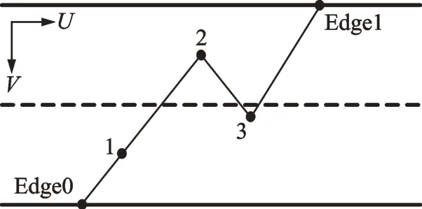
Fig.11 Diagram of the trajectory boundary

Therefore, total times of changing are noted.The cutter distribution according to total times of changing is shown in Table 1.
2.4 Cutting information planting
Cutting information is attached to the tracefile, including angles of cutter rotation,feed ratio and up/down actions of cutters.

Table 1 Two-cutter distribution
3 Experiments
An experimental cutting plantform is built up as shown in Fig.5. Cutting experiments are conducted to find out its problem.
3.1 Experimental conditions
According to the cutting conditions in the ATL,40 kHz ultrasonic frequency is chose in the experiments. T300 carbon fibre reinforced epoxy resin composite is used,and resin content is approximately 30%.
3.2 Experiments and analysis
3.2.1 Cutting
The cutting experiment in carried out on the two cutters platform. The sketch of cutting is shown in Fig.12.

Fig.12 Sketch of double cutting
Cutter 1 is nearer to the prepreg spool than cutter 2. When cut boundary“>”,cutter 1 starts to cut the“”boundary at point 0 first. Then cutter 2 cut the“/”boundary at the point 0 similarly by linear interpolation with spool when spool picks up the tape under it. Cutting boundary“<”is similar to boundary“>”. The start point of cutter 1 is point 1,but the start point of cutter 2 is point 2. In the other words,cutter 1 cuts the tape from point 1 to point 3 first,then cutter 2 cuts from point 2 to point 3.
3.2.2 Results
To ensure prepreg is cut smoothly, according to previous studies, velocities of U axis and V axis are set to 500 mm/s and 10 mm/s, respectively.The result of the experiments is shown in Fig.13.
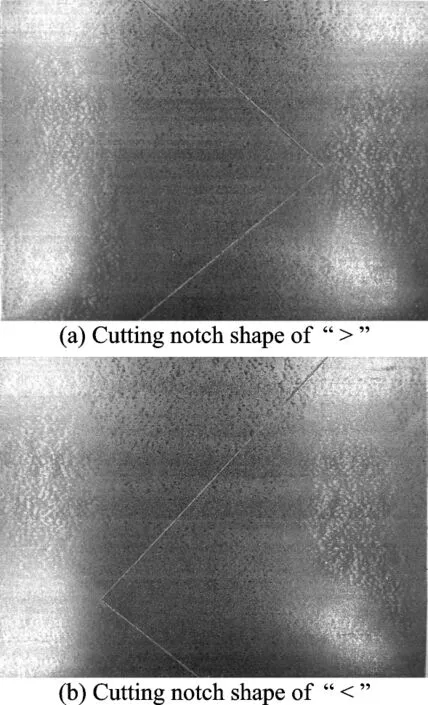
Fig.13 Results of cutting
As shown in Fig.13, the results of cutting are in good agreement with calculation, and two-cutter cutting experimental platform can realize its function. The experimental results show that concept of cutting platform is valid and cutting algorithm is correct.
4 Conclusions
Designing the prepreg cutting platform with two cutters and cutting algorithm based on two-step ATL is studied. CAD based cutter information generation algorithm is proposed. Experiments of twocutter cutting prepreg are carried out to verify the platform.
Experimental results show that prepreg cutting platform is able to cut boundaries with convex or concave polyline-shape by two cutters without revolving the prepreg spool. The experimental platform validates both the concept of cutting platform and cutting algorithm, and promotes the development of two-step ATL.
AcknowledgementThis work was supported by the National Science and Technology Major Project (No.2016ZX04002-005).
AuthorsDr. WEN Liwei received the B.S. and Ph.D. degrees in Electrical Engineering from Harbin Institute of Technology,Harbin,China,in 2000 and 2005,respectively.He joined the China Composite Materials Society and the Jiangsu Composite Materials Society as a director in 2007.From 2005 to present, he has been with College of Materials Science and Technology, Nanjing University of Aeronautics and Astronautics (NUAA),where he is currently an associate professor. His research has focused on technology and software of advanced composite material automation.
Mr. HUANG Xiaochuan received the M.S. degree in Materials Engineering from NUAA, Nanjing, China, in 2017.
Dr. QIN Lihua received the M.S. and Ph.D. degrees in Electrical Engineering from Harbin Institute of Technology, Harbin, China, in 2000 and 2005,respectively.He joined Beijing Institute of Space Long March Vehicle in May 2005,where he is a senior mechanical design engineer. His research is focused on application of aeronautical materials.
Dr. WANG Xianfeng received the M.S. and Ph.D. degrees in Electrical Engineering from Harbin Institute of Technology, Harbin, China, in 2004 and 2008,respectively. From 2008 to 2010, he was a director of China Composite Material Equipment Committee. From 2008 to present, he has been with College of Materials Science and Technology,NUAA. His research focuses on automated fiver placement,automated tape laying and relevant fields.
Prof. LI Yong received the B.S. and Ph.D. degrees in Materials Processing Engineering from NUAA, Nanjing, China,in 1993 and 2010, respectively. His research focuses on high-performance composites and automatic fiber placement of composites.
Author contributionsDr. WEN Liwei designed and conducted the experiment and wrote the manuscript. Mr.HUANG Xiaochuan conducted the experiment. Dr. QIN Lihua conducted the experimental evaluation. Dr. WANG Xianfeng and Prof. LI Yong commented on the manuscript and approved the submission.
Competing interestsThe authors declare no competing interests.
杂志排行
Transactions of Nanjing University of Aeronautics and Astronautics的其它文章
- Recent Advances in Hole Making of FRP/Metal Stacks:A Review
- Parameter Optimization for Improvement in Biomachining Performance
- Effect of Friction on Dynamic Response of A Power Split Transmission System
- Mathematical Model and Machining Method for Spiral Flute Rake Faces of Hourglass Worm Gear Hob
- Active Design Method of Tooth Profiles for Cycloid Drive Based on Meshing Efficiency
- Design and Study of Virtual Interventional Surgical System with Force Feedback
