Effect of surface blowing on aerodynamic characteristics of tubercled straight wing
2019-06-03GANESHARUNVINTHANNADARAJAPILLAI
N.GANESH,S.ARUNVINTHAN,S.NADARAJA PILLAI
Turbulence and Flow Control Lab,School of Mechanical Engineering,SASTRA Deemed University,Thanjavur 613401,India
KEYWORDS Active flow control;Aerodynamic efficiency;Biomimetics;Blowing;Tubercles
Abstract Recent research proves that wings with leading-edge tubercles have the ability to perform efficiently in post-stall region over the conventional straight wing.Moreover,the conventional straight wing outperforms the tubercled wing at a pre-stall region which is quintessential.Even though tubercled wing offers great performance enhancement,because of the complexity of the flow,the trough region of the tubercled wing is more prone to flow separation.Henceforth,the present paper aims at surface blowing-an active flow control technique over the tubercled wing to enhance the aerodynamic efficiency by positively influencing its lift characteristics without causing any additional drag penalty.Flow parameters like blowing velocity ratios and the location of blowing were chosen to find the optimised configuration keeping the amplitude and frequency of the leading-edge tubercles constant as 0.12c and 0.25c respectively.Numerical investigations were carried out over the baseline tubercled wing and tubercled wing with surface blowing at various blowing jet velocity ratios 0.5,1 and 2 over four different chordwise locations ranging from 0.3c to 0.8c.The results confirm that blowing at various x/c with different blowing velocity ratios performs better than the conventional tubercled wing.Comparatively,blowing velocity ratio 2 at 0.3c shows peak performance of about 28%enhancement in the lift characteristics relative to the baseline model.Particularly,in the pre-stall region,25-50%increase in aerodynamic efficiency is evident over the tubercled wing with surface blowing compared with the baseline case.Additionally,attempts were made to delineate the physical significance of the flow separation mechanism due to blowing by visualizing the streamline pattern.
1.Introduction
Active flow control over the airfoil is an important area of research in the aerospace community to improve the aerodynamic efficiency of the airplane.Increase in aerodynamic efficiency by reducing 1% drag results in lowering Direct Operating Cost(DOC)1of about 0.2%.Advancement in Computational Fluid Dynamics(CFD)leads to the prediction of the aerodynamic behaviour of the airfoil,and thus it reduces the experimental as well as financial difficulty.Recent developments in the flow control over the airfoil have been categorized into passive devices2-7and active devices.8-16Passive methods,such as altering the geometric dimensions to modify the surface pressure distribution to delay or prevent the flow separation.
An alternative to the passive control devices is active control devices,which significantly changes the aerodynamic characteristics through suction, blowing or both to provide additional kinetic energy to the molecules on the surface of the airfoil.Schematic view of the airfoil of the wing without and with blowing is shown in Fig.1.Genc¸et al.11numerically investigated the effect of blowing angle at low Reynolds number and found that blowing at 30°angle exhibits a significant change in lift-to-drag ratio L/D compared to other blowing angles like 45°and 90°.Further,they claimed that the blowing effectively alters the surface pressure distribution by delaying the flow separation.Later studies12-14found that increasing the amplitude of the tangential blowing further moves the separation point downstream towards airfoil trailing edge which in turn effectively increases the aerodynamic efficiency by 15%.Huang et al.15computationally investigated the effects of blowing on NACA0012 airfoil at 18°angle of attack and observed that in addition to stall delay characteristics it effectively reduces the drag.Goodarzi et al.17experimentally investigated the influence of blowing on airfoil featuring 0°,30°and 45°blowing angle and confirmed that optimal efficiency can be obtained using tangential blowing.Studies revealed that based on the location and blowing direction one can effectively alter the aerodynamic characteristics of the airfoil.The blowing control on the airfoil can also be used for effectively mitigating the production of lift when the aircraft is subjected to sudden gusts.
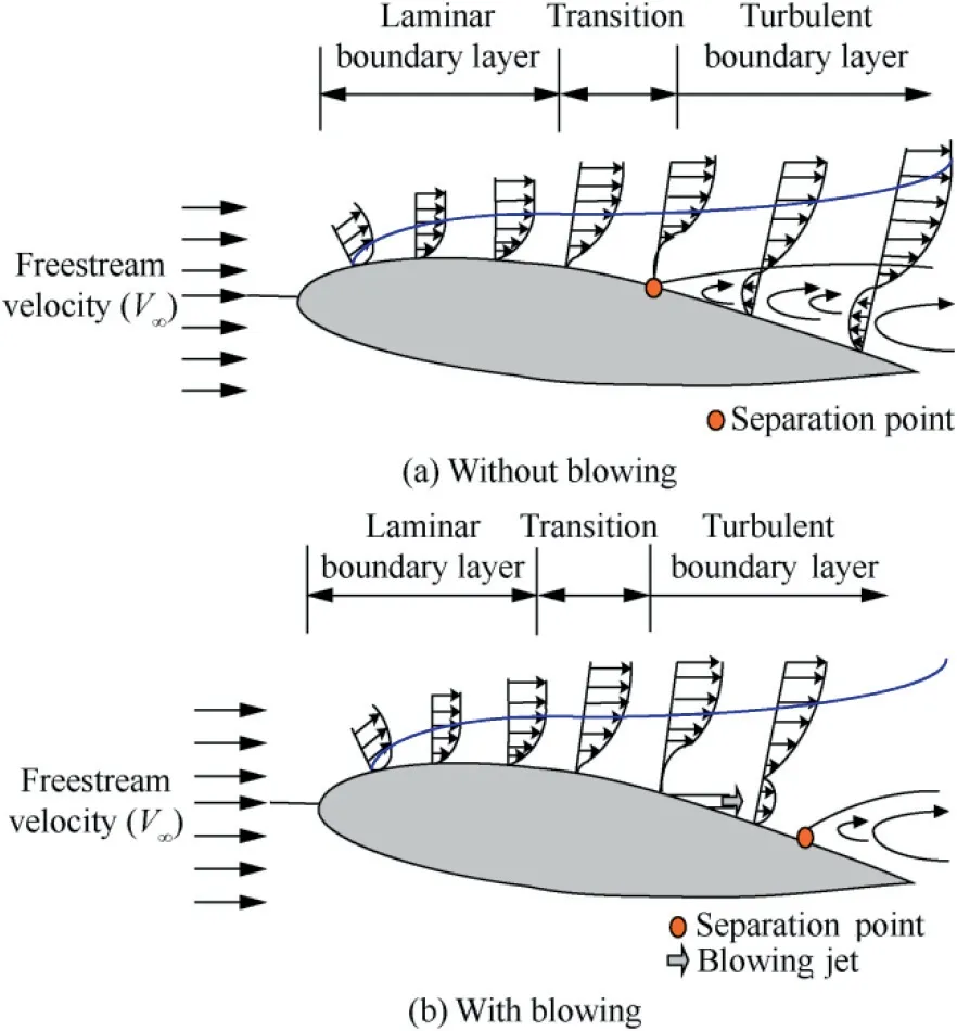
Fig.1 Shematic of velocity profile over airfoil without/with blowing.
Aimed at identifying the location and blowing direction of the jet slot,Al-Battal et al.18studied the effect of upstream tangential and normal blowing at various positions ranging from 0.08c to 0.95c.Their studies concluded that upstream tangential blowing outperforms the normal blowing.This is most likely due to the deflection of the shear layer upwards which in turn leads to the formation of a greater adverse pressure gradient over the surface of the airfoil.Location dependency test of the slots revealed that performing normal blowing in the leading edge tends to increase the lift coefficient CLin the pre-stall region whereas it has an adverse effect in the downstream region.
Huang et al.15extended the study by applying tangential blowing at the downstream locations and stated that downstream tangential blowing gives positive results relative to the conventional baseline model without blowing. Similar studies by Goodarzi et al.17confirmed the result stating that tangential blowing at downstream locations close to the trailing edge shows enhanced performance by effectively suppressing the boundary layer separation.Alexander et al.19utilized tangential blowing at the trailing edge to effectively control the circulation phenomenon over the airfoil at transonic Mach numbers.It is believed that the momentum imparted from the tangential blowing at the trailing edge slot effectively provides the circulation control.Henceforth,it becomes clear that the momentum imparted through the blowing is one of the key elements which need to be addressed.Sun and Sheikh 20 studied the effect of momentum coefficient on tangential blowing considering various momentum coefficient Cμlike 0.05,0.07 and 0.09.They claimed that blowing which possesses higher Cμrelatively provides more CL.It is also mentioned that Cμ=0.05 does not provide enough energy to influence the flow while Cμ=0.07 sufficiently alters the flow by vortex suppression but is incapable of delaying the separation completely.Cμ=0.09 imparts enough momentum to the flow capable of delaying the separation completely.In addition to the Cμ,the blowing amplitude is also of a primary concern because introducing blowing at low amplitudes might induce flow unsteadiness which may cause hysteresis effects.Following that researchers started focussing their attention on blowing amplitude and its effectiveness on the blowing characteristics.Dirlik et al.16found that increase in blowing amplitude corresponds to an increase in the lift to a certain extent.Goodarzi et al.17stated that the change in amplitude increases the lift without any drag penalty.James et al.10evaluated the aerodynamic characteristics influenced by the spanwise blowing over swept wings at various sweep angles and found that lowering the swept angle greater will be the effectiveness of the spanwise blowing.In recent years,researchers came up with an idea of using leading-edge tubercles on the aircraft wings inspired from the humpback whales as a passive flow control mechanism featuring stall delay without causing any additional drag penalty.Similar studies have been performed in Refs.21-28and they concluded that the modified leading-edge undulated wing outperforms the conventional baseline wing in the post-stall region.However,the performance characteristic of the modified leading-edge undulated wing in the pre-stall region is relatively low.
Even though several flow technologies are available to effectively control and manage the flow separation and its untoward effects on aerodynamic bodies.Although considerable attention has been made on the effect of blowing and its methodologies on conventional airfoil,the knowledge of blowing and its influence on bio-inspired leading-edge undulated model is unexplored to the extent of authors'knowledge.Hence,in this paper the numerical investigation of the blowing over the modified leading-edge undulated wing model has been reported considering the following parameters namely jet location(L)and blowing velocity ratio(R)at different angles of attack ranging from 0°to 45°with an increment of 5°.Additionally,attempts were made to elucidate the underlying flow physics featuring 3D flow structure.The primary objective of this research is to provide much deeper understanding on the aerodynamic characteristics of the modified tubercled wing with blowing.
2.Computational methodology
2.1.Physical model
Wings with NACA63(4)-021 airfoils having a similar crosssection to the flipper of a humpback whale were chosen to be the test model with a mean chord length of 1 m and a span of 2 m.The similar airfoil has been studied in Refs.21-28.The tubercles on the leading edge have been modelled based on the sinusoidal wave pattern represented by the following mathematical representationwhere A*=A/c and λ*=λ/c are the normalized amplitude and wavelength respectively.In this study,the wavy wing with a normalized amplitude of 0.12c and normalized wavelength of 0.25c is utilized.With a view to incorporate surface blowing technique in tubercled wing,the flow control parameters need to be identified.Dannenberg and Weiberg29examined different jet width for the airfoil blowing and claimed that the jet width area exceeding 2.5%c would not offer any benefit.Based on his report,the jet slot width is fixed at 2%c over the blowing surface of the wing.Moreover,the blowing velocity coming out of the jet slot must possess enough momentum to modify the shear flow.Gilarranz and Rediniotis30proposed that the influence of the blowing jet amplitude on the flow can be characterized by jet momentum coefficient Cμand further added that Cμshould be at least 0.002 to create an impact in altering the flow over the model.The jet momentum coefficient(Cμ)depends upon the blowing jet velocity ratio(R)in addition to the width of the jet slots(h)and the chord length of the model(c).The blowing velocity ratio(R),jet entrance velocities u,v,and jet momentum coefficient(Cμ)can be calculated using the following equations as outlined in Ref.15:
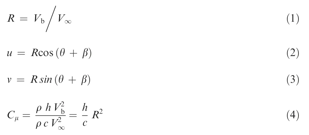
where β is the inclination angle between the jet surface and free-stream velocity direction.Considering tangential blowing,the angle between the jet surface and the jet entrance velocity direction(θ)is positioned at 0°.The blowing jet velocity ratio amplitude(R)considered in this study is 0.5,1 and 2 times the freestream velocity(V∞)and its corresponding jet momentum coefficient Cμhas been calculated as 0.005,0.02 and 0.08 respectively.Therefore,in a uniform free stream flow of velocity 30 m/s,various blowing jet amplitudes like 15,30 and 60 m/s possess enough momentum to create the necessary impact on the flow pattern.To identify the area dependency of the blowing control,the jet location has been varied from 0.3c to 0.8c.All the cases considered in this study were studied at a Reynolds number in the range of 2.05×10⁶at various angles of attack.The 3D view of the tubercled model without and with blowing is depicted in Fig.2 respectively.
2.2.Numerical method
Based on the framework of the previous researchers,it has been identified that the first-and second-order upwind methods were employed to solve the governing equations using Semi-Implicit Method for Pressure Linked Equations(SIMPLE).Among the several available turbulent models,k-ω,Shear Stress Transport(SST)seems to be the perfect fit for this numerical investigation of blowing over the airfoil surface as it exhibits excellent predictive capability for problems dealing with flow separation and wall turbulence.11,15,31In this study,the convergence tolerance has been set to 1×10⁻¹⁰for all the computed quantities.
2.3.Mesh and domain
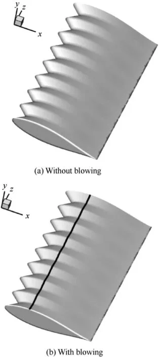
Fig.2 Geometry of tubercled model without/with blowing.

Fig.3 Computational domain and boundary conditions.
The coordinate system is shown in Fig.3 with the origin at the leading-edge point of the wing,and x,y and z axis measure along the streamwise,lateral and spanwise domain respectively.In the-x direction,the grid begins at around-7.5c upstream of the wing and stretches to 15c downstream of the wing in the x direction.Likewise,the domain stretches out to 10c away from the wing both in the+y and-y direction.However,in the-z direction the model is mounted on the wall and in the+z direction the boundaries are placed at 10c away from the tip of the wing.The wing model considered in this study possesses mean chord of length 1 m.The length of the computational domain along the chordwise distance is represented as(LC),normal to the chord as(LN)and the length of the computational domain in the lateral direction of the chord as(LZ).The computational domain is of size LC×LN-×LZ=22.5c×20c×10c to rule out any unnecessary disturbance created by the boundaries which tend to affect the flow near the model.As this study involves complex fluid flows near the wing,it necessitates high-quality grids near the body surface whereas coarser grids are formed away from the model.To generate an accurate mesh,algebraic initial point distribution32has been used for surface grids.
2.4.Operating conditions
For boundary conditions,uniform inlet velocity is imposed on the upstream boundary and the outlet is defined as pressure outlet where intensity and turbulence viscosity ratio is considered since it captures turbulence for the k-ε and k-ω models.However,no-slip wall boundary condition is used for the wing(except at jet slot).Table 1 illustrates the set of boundary conditions specified for the analysis.Blowing is achieved by the constant tangential velocity on the wall as shown in Fig.4(a).The amplitude of the blowing is set to be varying based on the blowing velocity ratio(R).Aimed at identifying the location dependency of the blowing control,blowing is applied at different locations ranging from 0.3c to 0.8c respectively as shown in Fig.4(b).
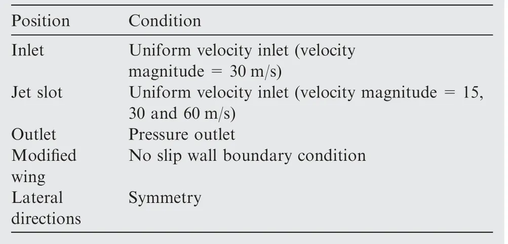
Table 1 Boundary conditions.
2.5.Grid independence and numerical validation
Grid independence test has been carried out for multiple sets of grids(0.1-1 million elements respectively)with increasing mesh density as shown in Fig.5.Table 2 shows the calculated aerodynamic coefficients for various grids at 10°angle of attack.The computational domain was discretized with approximately 0.8 million hexahedral cells.This was achieved by considering the aforementioned grid with increasing mesh density to a point where the solution exhibits independence for the increase in the total number of cells/grid points any further.Additionally,the trend line of the characteristic lift and drag curves were validated against Johari et al.21
The details of the different test cases of investigations are presented in Table 3.
3.Results and discussion
A steady tangential blowing with various blowing velocity ratios(R)is applied at multiple chordwise locations of the leading-edge undulated wing model and the results were compared with the baseline leading-edge undulated model without blowing in the range of 0-45°in increments of 5°.The results of the numerical investigation are presented in this section.
3.1.Effect of blowing velocity ratio
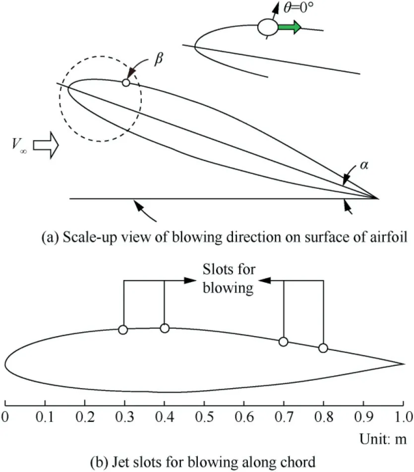
Fig. 4 Schematic representation of jet slots and blowing direction.
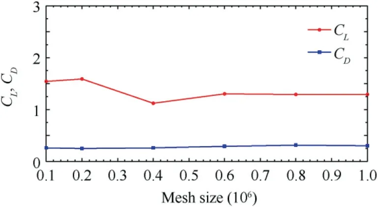
Fig.5 Convergence report of CL and CD.
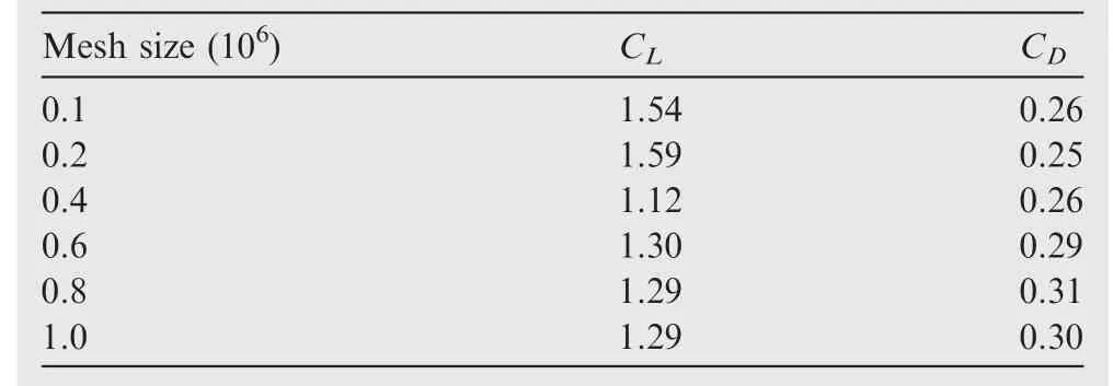
Table 2 Grid independence test results.
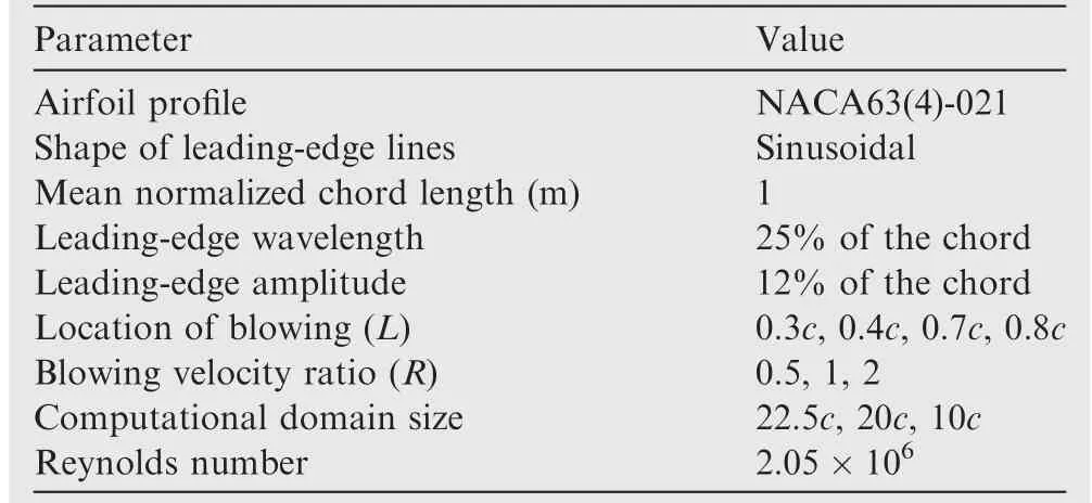
Table 3 Details of various cases of investigation.
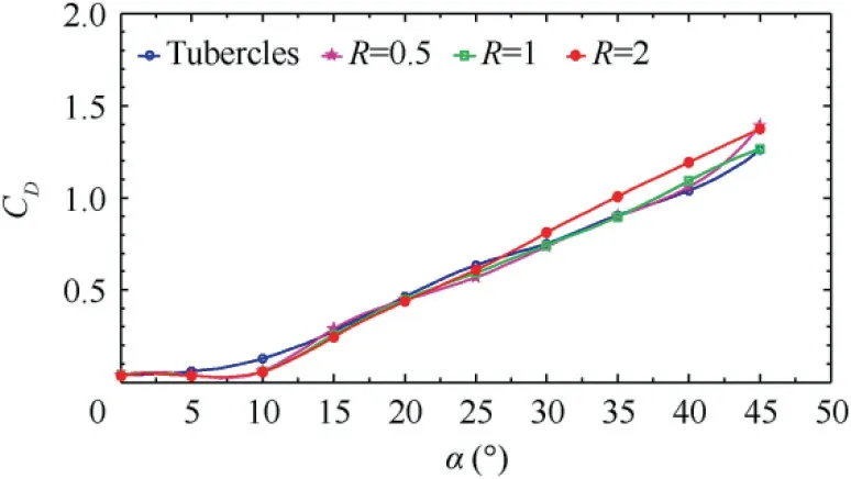
Fig.6 Drag coefficient at various angles of attack with different blowing velocity ratios.
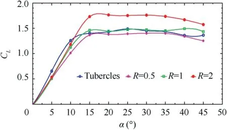
Fig.7 Lift coefficient at various angles of attack with different blowing velocity ratios.
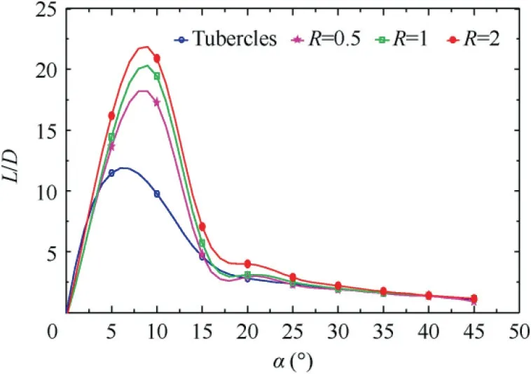
Fig.8 Variation of lift-to-drag ratio with angle of attack at different blowing velocity ratios.

Fig.9 Drag coefficient for various angles of attack at different blowing locations.
The effect of chordwise steady blowing applied at a location of 0.3c for different blowing velocity ratios(R)on drag coefficient,lift coefficient and lift/drag is presented from Fig.6 to Fig.8 respectively.Fig.6 shows that the drag coefficient for the baseline tubercled wing without blowing is dominant in the pre-stall region over the modified leading-edge undulated wing with blowing.It can also be inferred that the drag coefficient of the baseline and the modified wing with blowing shows little dependence on the blowing velocity ratio(R)relative to the baseline tubercled wing.In the post-stall regime,the drag coefficient increases with the increase in the angle of attack.The lift coefficient depicted in Fig.7 does not provide any significant positive effect in the pre-stall region,which is also confirmed by the theories postulated by previous research.13,20However,in the post-stall region,the blowing velocity ratio R=2 appears to be the best performance,when compared to the other blowing velocity ratios like R=0.5 and 1.Fig.8 shows the L/D which is maximum of 23 at 10°angle of attack.Further,it can be observed that at higher angles of attack,the L/D decreases with the increase in angles of attack.
3.2.Effect of blowing location
The coefficient of drag for various angles of attack at different blowing locations for multiple blowing velocity ratios R=0.5,1 and 2 is shown in Fig.9.It is apparent from the graphs that the increasing trend of coefficient of drag has been seen with the increment in the angle of attack.Additionally,it is found that the influence of blowing location on the coefficient of drag is less significant,and chordwise blowing at 0.3c-0.8c shows the almost similar coefficient of drag as the baseline tubercle configuration.
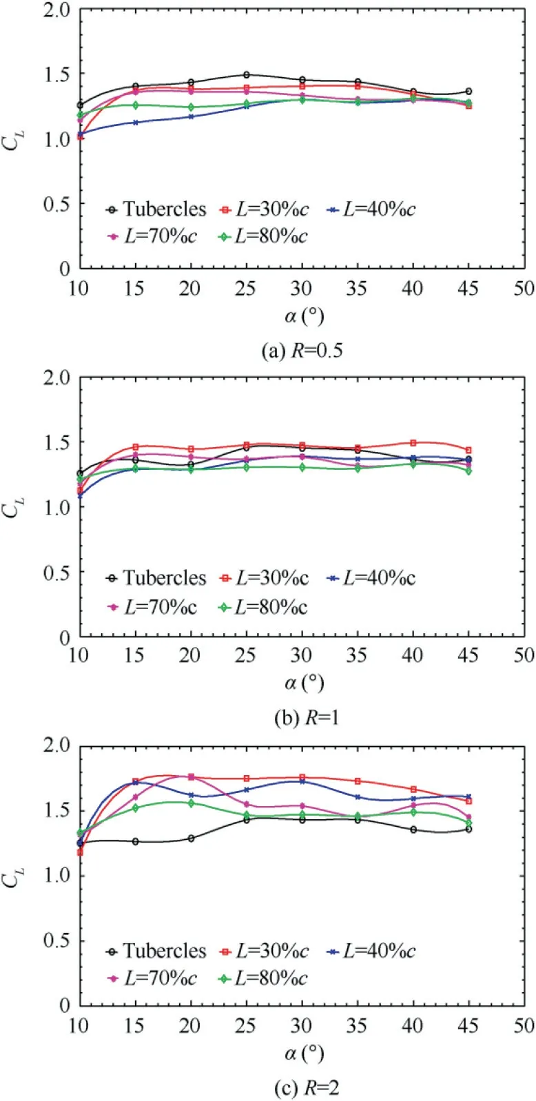
Fig.10 Lift coefficient for various angles of attack at different blowing locations.
Fig.10 depict the coefficient of lift vs angle of attack for an operating range of 10-45°with an increment of 5°.At blowing velocity ratio R=0.5,the effect of blowing at the various locations exhibits an adverse effect as shown in Fig.10(a).When R=1,the blowing at 0.3c shows the significant increase in CLwhile all the other blowing location has the similar effect of the baseline tubercled wing as shown in Fig.10(b).Moreover,in the case of R=2,even though all the chordwise blowing locations show significant improvement in CL,a peak increase in CLhas been observed at 0.3c where the CLvalues have been increased from 1.25 to 1.75 showing nearly 40%rise.
Fig.11 represent the L/D for different blowing jet velocity ratios R=0.5,1 and 2 at various angles of attack.It can be clearly seen that the L/D for 10°angle of attack increases with the increase in blowing velocity ratio R.However,in all other cases,the L/D is similar to that in the case of baseline tubercled wing.
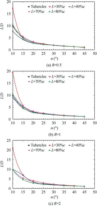
Fig. 11 Lift-to-drag ratio for various angles of attack at different blowing locations.
3.3.Streamline pattern and pressure distribution
Three-dimensional flow structure pattern for tubercled wing without and with blowing at 20°are shown in Fig.12.At 20°angle of attack,the free-stream flow follows a bi-periodic flow pattern.Studies by Custodio23and Johari et al.21also exhibit similar flow pattern over the airfoil surface.The flow mechanism can be explained as follows.
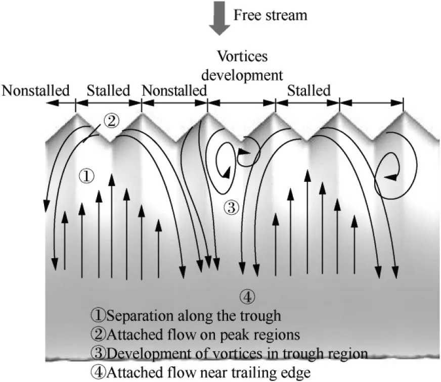
Fig.13 Pictorial representation of flow structure on baseline tubercled wing.
It can be seen that in the modified tubercled wing with blowing the prolonged attached flow can be observed relative to the baseline tubercled wing without blowing.However,in the baseline tubercled wing without blowing,the flow starts separating from the trough region.When the flow starts separating from the surface,it extends in the spanwise direction till the trailing edge without any flow reattachment. The biperiodic flow pattern and its corresponding flow separation are prevalent over the entire span of the test model.As the flow moves towards the trailing edge,the separated regions formed from different bi-periodic flow patterns converge together.Because of this phenomenon,the flow condition is basically unstable,which in turn keeps switching between the tubercles forming a sequential stall condition.The similar flow phenomenon has been confirmed by Cai et al.33and Wei et al.34in their recent studies.They claimed that tubercled wing stall pattern includes a combination of stalled and non-stalled regions changing alternatively as shown in Fig.13.This alternating bi-periodic flow pattern ensures that some of the flow remains attached even at greater angles of attack attributing to the stall delay characteristics.It is believed that the small vortices that start forming from the trough region progress with the increase in time for forming the successive biperiodic patterns.
At R=2,when blowing is applied at 0.3c location,it can be clearly seen that the blowing divides the larger flow separation region into small one eventually leading to enhanced flow over the airfoil surface as shown in Fig.12(b).In other words,it weakens the strength of the vortices and thereby leads to the attached flow over the majority of the upper surface.Additionally,the steady tangential blowing restricts the development of small vortices into a bigger one.Likewise,at 25°angle of attack,the similar flow pattern has been observed and is displayed in Fig.14(a)and(b)respectively.From this,it can also be inferred that the flow remains still attached to the airfoil surface.It is found that beyond 25°angle of attack,the formation of the bi-periodic pattern is very unstable and the rate at which it occurs speeds up.
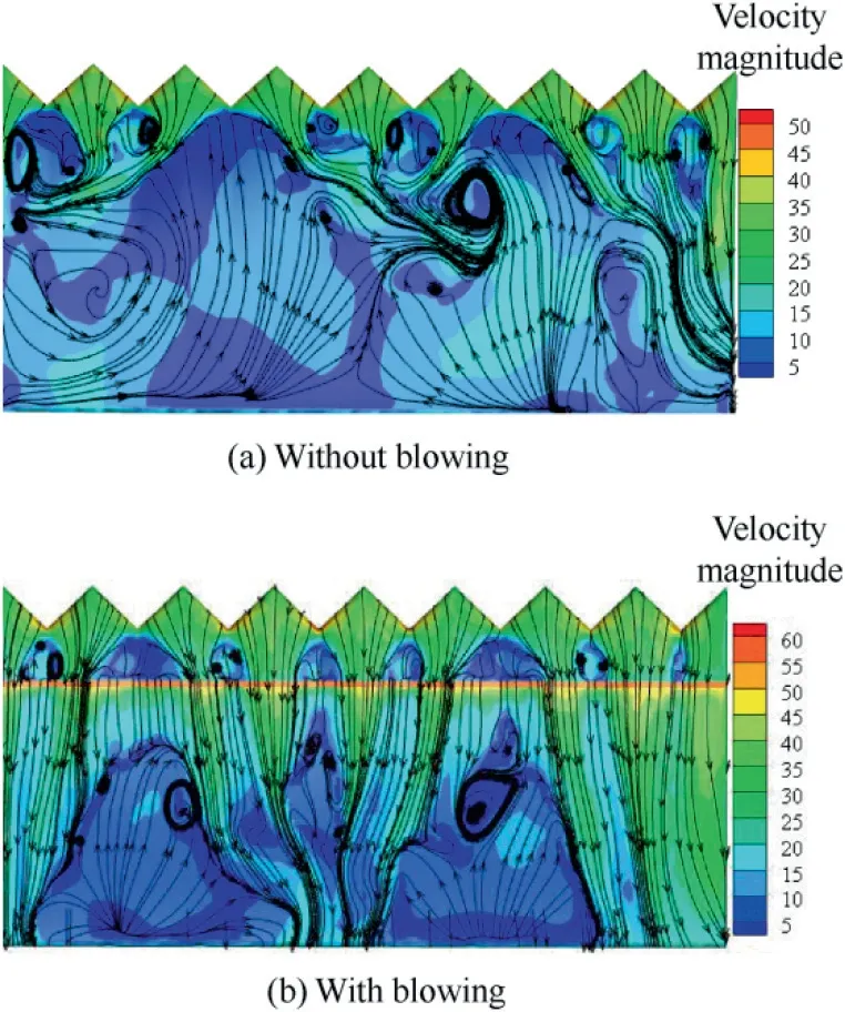
Fig.14 Surface flow structure of tubercled wing at 25°angle of attack at R=2.
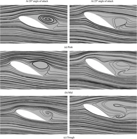
Fig.15 Streamline pattern for tubercled wing.
Surface streamline flow pattern at the peak, mid and trough section of the baseline tubercled wing at 20°and 25°are shown in Fig.15.At 20°,it can be seen that the recirculation region present at the peak is predominant;at the midsection the flow reattaches near the trailing edge and the separation bubble is visible whereas at the trough region the distance between the point of separation and the point of reattachment is relatively low.When it exceeds the critical angle of attack,the flow pattern changes.The separation bubble in the mid and trough region combines together creating a more complex flow pattern.
The streamline pattern for the tubercled wing with blowing at 20°and 25°angles of attack featuring R=2 at 0.3c are shown in Fig.16.It is evident that the flow is completely attached over the entire surface of the wing.It signifies that the blowing imparts momentum to the flow which in turn completely eliminates the recirculation region.Under the integrated effects of leading-edge tubercles and the blowing,the attached flow can be observed over the entire airfoil.Likewise,the similar phenomenon has been noticed in the peak and midsection of the 25°case.However,near the trailing edge of the trough section,a small flow distortion can be seen.The main reason may be the flow instability induced by the combined effects of the flow interaction between the leading-edge tubercles and the blowing.
Fig.17 shows the comparison of CLwith R=2 at various chordwise blowing locations(L).It is concluded that the blowing at 0.3c location provides higher CLfor post-stall angles of attack whereas its influence is less likely significant in the prestall angles.
4.Conclusions
In this study,the effect of blowing velocity ratio(R)and blowing location(L)has been studied on a baseline tubercled wing and a modified tubercled wing with blowing.Blowing velocity ratio has been varied with R=0.5,1 and 2 for various locations 0.3c-0.8c at various angles of attack ranging from 0°to 45°in increments of 5°.Based on the above study,the following conclusions are made.
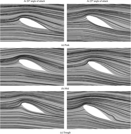
Fig.16 Streamline pattern for tubercled wing with blowing at R=2 at x/c=30%.
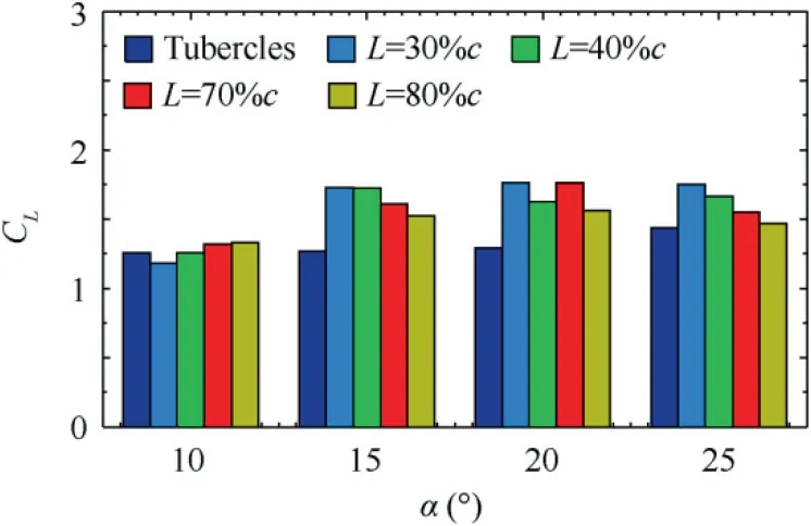
Fig. 17 Comparison of CL with R=2 at various blowing locations.
(1)Blowing velocity ratio is effective at R=2 in both the pre-stall and post-stall angles.Moreover,in the prestall region,it improves the aerodynamic efficiency from 25%to 50%for the leading-edge tubercled wing.
(2)The optimised blowing location is found as 30%of the chord on the wing.Beyond 0.3c,the influence of blowing is less significant irrespective of various blowing velocity ratios.
(3)The streamline pattern observed over the leading-edge tubercled wing with blowing shows that the improvement in the aerodynamic characteristics is due to the addition of momentum through blowing jet,which in turn delays the flow separation by energising the flow.
(4)In the trough region of the leading-edge tubercled wing with blowing,the separated region is washed away.Indeed,even at higher angles of attack,the flow on the downstream of the wing is still attached as a result of blowing.
(5)Generally,the leading-edge tubercled wing is less prone to abrupt stall compared to the normal wing without tubercle.Hence,the coefficient of lift at 15°maintains throughout till 45°.This phenomenon continues for various blowing velocity ratios too.
Tubercled wing with the optimized blowing velocity ratio and location can be adopted in order to improve the aerodynamic efficiency. Various other parameters like amplitude and frequency of the tubercles,blowing velocity ratio and blowing location can be extensively studied before going for the commercial practice,and the experimental investigation of the flow instability over the tubercled wing with blowing will be the focus of our future research.
Acknowledgements
This research work was supported by the Science Engineering Research Board(SERB),Department of Science&Technology(DST),Government of India(No.ECR/2017/001199).The authors thank SERB/DST for their financial assistance in carrying out this research work through Early Career Research Award.
杂志排行
CHINESE JOURNAL OF AERONAUTICS的其它文章
- Special Column:NDT and SHM in Aerospace
- Hypervelocity impact induced shock acoustic emission waves for quantitative damage evaluation using in situ miniaturized piezoelectric sensor network
- Multiphysics simulation method of Lamb wave propagation with piezoelectric transducers under load condition
- A Lamb wave signal reconstruction method for high-resolution damage imaging
- Online condition diagnosis for a two-stage gearbox machinery of an aerospace utilization system using an ensemble multi-fault features indexing approach
- Effects of blade aspect ratio and taper ratio on hovering performance of cycloidal rotor with large blade pitching amplitude
