A Lamb wave signal reconstruction method for high-resolution damage imaging
2019-06-03XiaopengWANGJianCAIZhiquanZHOU
Xiaopeng WANG,Jian CAI,Zhiquan ZHOU
State Key Lab of Mechanics and Control of Mechanical Structures,Nanjing University of Aeronautics and Astronautics,Nanjing 210016,China
KEYWORDS Damage imaging;Dispersion compensation;High resolution;Lamb waves;Signal reconstruction
Abstract In Lamb wave-based Structural Health Monitoring(SHM),a high-enough spatial resolution is highly required for Lamb wave signals to ensure the resolution and accuracy of damage detection.However,besides the dispersion characteristic,the signal spatial resolution is also largely restricted by the space duration of excitation waveforms,i.e.,the Initial Spatial Resolution(ISR)for the signals before travelling.To resolve the problem of inferior signal spatial resolution of Lamb waves,a Lamb Wave Signal Reconstruction(LWSR)method is presented and applied for highresolution damage imaging in this paper.In LWSR,not only a new linearly-dispersive signal is reconstructed from an original Lamb wave signal,but also the group velocity at the central frequency is sufficiently decreased.Then,both dispersion compensation and ISR improvement can be realized to achieve a satisfying signal spatial resolution.After the frequency domain sensing model and spatial resolution of Lamb wave signals are firstly analyzed,the basic idea and numerical realization of LWSR are discussed.Numerical simulations are also implemented to preliminarily validate LWSR.Subsequently,LWSR-based high-resolution damage imaging is developed.An experiment of adjacent multiple damage identification is finally conducted to demonstrate the efficiency of LWSR and LWSR-based imaging methods.
1.Introduction
Lamb waves are a kind of guided ultrasonic waves existing in thin-wall structures.With the ability of long distance travelling and high sensitivity to both surface and internal defects,Lamb waves have been widely used as a promising tool in Structural Health Monitoring(SHM)of plate-like structures.1-6In practical applications,the spatial resolution of Lamb wave signals is undoubtedly a vital factor to determine the resolution and accuracy of damage detection.For a diagnostic signal of inferior spatial resolution,its useful defect-relevant wavepackets are easily overlapped and interfered with each other or by others.Signal interpretation would become less straightforward to make the extraction of damage information difficult.As a result,final detection results are badly affected.To ensure the resolution and performance of Lamb wave damage identification,an adequately high spatial resolution of Lamb wave signals is required.
Due to multi-mode and dispersion characteristics,the propagation of Lamb waves is extraordinarily complicated.Even for single-mode signals,dispersive wavepackets will spread out in time and space with their waveforms distorted as they propagate.7This can definitely degrade the signal spatial resolution.To resolve the dispersion problem,a Time Reversal Process(TRP)was introduced to automatically compensate the dispersion effect without any priori-knowledge of Lamb wave dispersion properties.8Unfortunately,the Time of Flight(TOF)of the compensated signals is also eliminated at the same time to result in much inconvenience to damage localization.9Another strategy for Lamb wave dispersion compensation is Fourier-domain signal processing using wave dispersion relations.Wilcox performed dispersion removal by mapping Lamb wave signals from time to distance domains.10The Time-Distance Domain Mapping(TDDM)method was then applied to advance the capacities of Lamb mode diversity imaging,11phased array beamforming,12and AE source locating.13Some improvements for TDDM were also made considering signal waveform correction.14,15Liu and Yuan proposed a Linear Mapping(LM)technique,in which the former nonlinear wavenumber relation is linearly expanded as a firstorder Taylor series for dispersion eliminating.16From LM,approaches of Linearly-Dispersive Signal Construction(LDSC) and Non-Dispersive Signal Construction (NDSC)were developed and applied for dual neighboring damage imaging.17,18Marchi et al.carried out Lamb wave dispersion compensation with Warped Frequency Transform (WFT)and extended the compensation procedure to irregular waveguides.19Fu et al.presented a step pulse excitation-based WFT method for dispersion suppression.20
Using the above compensation approaches,every wavepacket in a Lamb wave signal can be well recompressed and recovered.Nevertheless,restricted by the time-space duration of its excitation waveform,i.e.,the Initial Spatial Resolution(ISR)for the signal before travelling,the signal spatial resolution could remain inadequate for achieving a satisfying damage identification resolution.To further improve the Lamb wave signal resolution,Pulse Compression(PuC),initially developed for radar systems to address the trade-off between the resolution and SNR during signal transmission, was recently adopted together with dispersion compensation.Marchi et al.carried out PuC after WFT to increase the damage localization accuracy in an aluminum plate.21Lin et al.investigated different Lamb wave excitation waveforms for attaining the optimal results of PuC and dispersion compensation.22Malo et al.utilized dispersion eliminating and PuC to actualize 2-D compressed pulse analysis for ultrasonic guided waves in an aluminum rod.23During these processing procedures,PuC is essentially equivalent to employing impulselike auto-correlation waveforms as new excitation signals with a narrower temporal width,for increasing the ISR.However,far from impulses,much broader auto-correlation waveforms were obtained in reality,22even using carefully-designed PuC excitation signals.
To efficiently enhance the resolution and capability of Lamb wave identification,a Lamb Wave Signal Reconstruction(LWSR)approach is presented in this paper.In LWSR,not only a new linearly-dispersive signal is reconstructed from the original Lamb wave signal for dispersion compensation,but the group velocity at the central frequency is also decreased in multiples to sufficiently improve the ISR.Thus,an outstanding signal spatial resolution can be obtained in the reconstructed signal.The remaining content is organized as follows.Some fundamental analysis is performed for Lamb wave signals in Section 2.LWSR is proposed in Section 3,in which the basic idea and numerical realization are theoretically investigated and numerically validated. In Section 4, an LWSR-based high-resolution damage imaging method is developed.Experimental validation for LWSR and LWSRbased adjacent multiple damage imaging is arranged in Section 5.Conclusions are made in the last section.
2.Fundamental analysis for Lamb wave signals
2.1.Sensing model in frequency domain
For the convenience of theoretical investigation,a Lamb wave sensing model is simplified in frequency domain before the signal spatial resolution analysis. With PieZoelecTric (PZT)wafers applied as actuators and sensors,a Lamb wave signal assumed of a single wavepacket can be represented in frequency domain as17,18

where ω, Va(ω), and V0(ω) are the angular frequency,frequency-domain excitation signal,and sensor signal,respectively.H(ω),regarded as the transfer function of the whole procedure including Lamb wave exciting,propagating,and sensing,can be expressed as

where A(r,ω)is the amplitude spectrum of H(ω),r is the travelling distance,K0(ω)is the wavenumber of the Lamb wave mode,and

where cp(ω)and cg(ω)are the phase and group velocities of the mode,respectively
For the narrowband excitation signal Va(ω),A(r,ω)varying slightly within the limited frequency range can be simplified as‘‘1”to facilitate the following analysis.The sensing model is derived as

Applying Inverse Fourier Transform(IFT)to Eq.(4),the time-domain Lamb wave signal v0(t)can be calculated.
2.2.Spatial resolution of Lamb wave signals
The spatial resolution of v0(t)can be generally estimated as the Resolvable Distance(RD)of its signal wavepacket,7i.e.,

where cg0and T0are the group velocity of the Lamb wave mode at the central frequency and the initial temporal duration of the wavepacket before travelling,respectively.Tdisp,the increased time duration of the wavepacket caused by dispersion,can be calculated as7

Clearly,the signal could possess a high spatial resolution with a short RD.Eqs.(5)and(6)indicate that,for v0(t)of severe dispersion,cgmaxdiffers much from cgmin.Tdispwould rapidly rise as the signal wavepacket travels over increasingly long r,resulting in a large RD and a seriously-degraded signal spatial resolution. Hence, several dispersion compensation approaches have been introduced to remove Tdispfor improving the resolution of Lamb wave signals and damage detection.10-20
However,as expressed by Eq.(5),RD is not only dependent on Tdisp.When the dispersion effect has been well compensated,Tdisp=0 in Eq.(5).The signal spatial resolution is simplified as the RD of the pristine signal wavepacket at its exciting site,i.e.,

where RD0,actually the space duration of the original excitation wavepacket,can be regarded as the value of the Initial Spatial Resolution(ISR)for the Lamb wave signal.
Eqs.(5)and(7)reveal that,besides the dispersion effect manifested as Tdisp,the signal spatial resolution is also highly restricted by its ISR.For a Lamb wave signal with an overhigh RD0to have an insufficient ISR, the useful defectrelated wavepackets in the signal could still be seriously overlapped and interfered with each other or by other ones even without dispersion.Signal interpretation and flaw information extraction would become extremely hard.As a result,the resolution and accuracy of Lamb wave damage detection are severely impaired.
3.LWSR method
As analyzed above,to adequately improve the signal spatial resolution of Lamb waves,besides dispersion compensation,the enhancement of the ISR should be further made by decreasing RD0.From Eq.(7),RD0is proportional to cg0and T0.In practical applications,once the excitation waveform,for instance,the commonly-used windowed tone burst,is decided to acquire single-mode Lamb wave signals,T0is basically fixed and inconveniently modified. Alternatively,the ISR could be enhanced through cg0reduction,which is exactly executed by the proposed Lamb Wave Signal Reconstruction(LWSR).In LWSR,not only a linearly-dispersive version of the original Lamb wave signal is reconstructed for dispersion removal,17but also the former cg0is numerically decreased in multiples to make the ISR of the new reconstructed signal greatly surpass that of the original signal.Then,a satisfying signal spatial resolution can be achieved.In this section,based on the frequency-domain sensing model,the basic idea and realization of LWSR are theoretically investigated and preliminarily testified with numerical simulations.
3.1.Basic idea of LWSR
It can been seen from Eq.(4)that the propagation characteristics of V0(ω)are mainly determined by K0(ω).For a dispersive v0(t),K0(ω)is nonlinear with ω.9,17,18Different frequency components of V0(ω) will have inconsistent time delays K0(ω)r/ω to cause the signal wavepacket spreading out by Tdisp.Furthermore,from Eqs.(3)and(7),the ISR of V0(ω)is limited as RD0=T0cg0=T0dω/d[K0(ω)]|ω=ωc,where ωcis the central angular frequency of V0(ω).Hence,it is the former nonlinear wavenumber relation K0(ω)that brings about the inferior spatial resolution of V0(ω).Regarding this problem,a signal V1(ω)of an outstanding spatial resolution can be reconstructed in LWSR to replace the original Lamb wave signal V0(ω),by substituting the former wavenumber relation K0(ω)in Eq.(4)with the newly designed one K1(ω).
To remove the nonlinear K0(ω)-induced dispersion,K1(ω)requires linearizing as a first-order expansion of K0(ω)around ωc17as follows:

where k0and k1are the parameters of zero-and first-order items of K1(ω),respectively.
More importantly,to enhance the ISR by means of decreasing cg0,K1(ω)should satisfy

where cg1is the decreased group velocity of the newly reconstructed V1(ω)at ωc,and m ≥1 is the adjusting factor for cg1.From Eqs.(8)-(10),the parameters of K1(ω)can be derived as

To theoretically investigate LWSR results,the exact expression of V1(ω)under K1(ω)can be deduced in time domain,with the excitation signal represented as an amplitudemodulated harmonic17,18as follows:

where va(t)is the time domain excitation signal.n(t)is the amplitude modulation function specifying the envelope of va(t), N(ω)=∫n(t)e-iωtdt is the Fourier Transform (FT)result of n(t),and the carrier frequency ωccorresponds to the central angular frequency of va(t).Note that,for the convenience of analysis,the practically real va(t)is expressed in a complex one.
Inserting Eqs.(12b)and(8)into Eq.(4)and applying IFT,It can be derived with the shifting property of FT as17,18

where v1(t)denotes the time-domain expression of V1(ω).
With Eqs.(3),(11),and(12a),v1(t)can be ultimately reformulated as

Eq.(14)proves that v1(t)is just a va(t)delayed by the travelling time mr/cg0corresponding to the decreased group velocity cg1.Due to the extra factorthe initial phase of the carrier frequency ωcof v1(t)is entirely shifted by ωcwhich fortunately produces no deformation on the signal envelope n(t),17i.e.,the wavepacket shape.Therefore,under K1(ω),v1(t)can exempt from the influences of a nonlinear dispersion relation and too high cg0.From Eqs.(7)and(10),the RD of v1(t)is successfully reduced to cg1T0= RD0/m.The whole spatial resolution of v1(t)is heightened to m times as just compared with the ISR of the original V0(ω).This means that a high spatial resolution is obtained in v1(t)via LWSR.
3.2.Realization of LWSR
3.2.1.Computation of phased-delay factor under K1(ω)
LWSR can be numerically realized based on the signal construction principle.18With Va(ω)known in priori,from Eq.(4),the crucial problem for reconstructing V1(ω)is how to pursue the phase-delay factor e-iK1(ω)r,considering that the traveling distance r is probably unknown especially for a damage-scattered signal.The general expression of e-iK1(ω)rcan be rewritten in a composite function as

where the subfunction is the wavenumber relation K(ω)while the generating function E(r,k)=e-ikr.For a given r,E(r,k)is merely a simple exponential function and irrespective of K(ω).This implies that E(r,ω)under various dispersion relations are subject to an identical E(r,k).
As described by Eq.(15),E(r,k)and E(r,ω)are the two distinct functions in wavenumber or frequency domain,but share the same functional values.Mathematically,performing wavenumber-domain interpolation to E(r,k)at equally-spaced frequency points decided by k=K(ω)will result in E(r,ω).Vice versa,E(r,k)can be gotten by interpolating E(r,ω)in frequency domain with even wavenumber intervals in terms of ω=K-1(k),where K-1(k)is the inverse function of K(ω).Thus,for V1(ω)and V0(ω)of identical propagation paths but different dispersion relations K1(ω) and K0(ω), their phase-delay factors, rewritten as E0(r,ω)=E (r ,K0(ω))= e-iK0(ω)randrespectively,can be numerically converted to each other on the basis of the common E(r,k)via the frequency-or wavenumberdomain interpolation process.This can definitely provide an approach to calculate E1(r,ω) with K0(ω), K1(ω), and E0(r,ω),as illustrated by the dashed arrow lines in Fig.1.That is:
(1)After the inverse functionis established from wavenumber domain,the phase-delay factor E ( r,K1(ω))under the new linear dispersion relation K1(ω),i.e.,E1(r,ω)in frequency domain,is obtained.

According to the calculating procedure,E1(r,ω)can be mapped into E0(r,ω)as K0(ω),frequency-domain interpolation is carried out to E0(r,ω) at, and E(r,k) is gotten in wavenumber domain.
(2)By implementing interpolation to E(r,k)at k=K1(ω)in
where

is the interpolation mapping sequence from E0(r,ω) to E1(r,ω).
Eq.(16)suggests that E1(r,ω)can be straightforwardly attained from E0(r,ω) through only one time frequency domain interpolation with Ω1(ω),as illustrated by the solid arrow line in Fig. 1. By doing this, E(r,k) and the wavenumber-domain interpolation for it is not demanded.Both the interpolation error and computation cost can be decreased.
3.2.2.Fast realization of LWSR
v1(t)can be reconstructed by inserting Eq.(16)into Eq.(4)and applying IFT as

Note that the travelling distance r,already presented in the phase-delay factor E0(r,ω),is not expressly needed in signal reconstruction.
With Fast Fourier Transform (FFT) and Inverse Fast Fourier Transform(IFFT)operations,efficient LWSR for actually discrete Lamb wave signals can be expected.From Eq.(18),K0(ω),K1(ω),and the phase-delay factor E0(r,ω)should be firstly determined to calculate v1(t).K0(ω)can be theoretically derived from the Relay-Lamb dispersion equation using structure material parameters. Then, K1(ω) is decided by linearizing K0(ω)with Eqs.(8)and(11).
As for the phase-delay factor E0(r,ω),Eq.(2)indicates that E0(r,ω)is equivalent to the transfer function H(ω)with the amplitude A(r,ω)normalized.Essentially,H(ω)is the frequency spectrum of the temporal impulse response captured by the sensor.Hence,H(ω)as well as E0(r,ω)can be gained by FFT to the impulse response,which can be acquired under impulse or step pulse broadband excitation.9,20
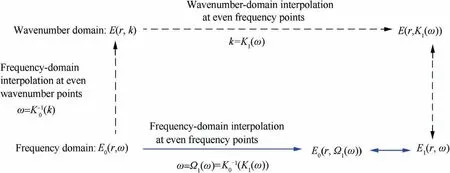
Fig.1 Procedure of calculating E1(r,ω)with K0(ω),K1(ω),and E0(r,ω).
With Eq.(18)and using the convolution property of FFT,v1(t)can be finally calculated as

Eq.(19)is the fast calculation formula of LWSR.Stemming from the same signal construction principle,20LWSR can be taken as the improved Linearly Dispersive Signal Construction(LDSC)approach.17Their main distinction lies in that the previous cg0maintaining unchangeable during LDSC is decreased by m-1 times in LWSR to further increase the ISR.Consequently,LWSR outperforms LDSC in enhancing the whole signal spatial resolution.
Before implementing LWSR,it is necessary to note that:
(1)v0(t)is supposed of a single wavepacket in the above analysis.When v0(t)contains N ≥2 wavepackets of common dispersion characteristic K0(ω),based on the time-invariant linear system theory,the transfer function can be rewritten aswhere Hn(ω)≈e-iK0(ω)rnis the transfer function of the n-th wavepacket with a travelling distance of rn.Substituting H′(ω)into Eq.(19)and using the linear property of FFT, it can be deduced that v1(t)=IFFT[Va(ω)This demonstrates that LWSR remains applicable to a signal composed of multiple wavepackets with identical dispersion relations.Moreover,the final processing result is equal to the sum of the results of LWSR on every wavepacket.
(2)Because of the large reduction of cg1during LWSR,much deviation between K0(ω)and K1(ω)can be produced even within the bandwidth of V0(ω).The frequency range of the mapped points Ω1(ω) decided with Eq.(17)will be unavoidably extended so large that[ Ω1(ω1) Ω1(ω2)]would be apparently broader than[ ω1ω2],where [ ω1ω2]is the previous angular fre-[ Ω1(ω1) Ω1(ω2)].
(3)The appropriate adjusting factor m should be carefully determined during LWSR.For one thing,the spatial resolution of v1(t), evaluated as cg0T0/m, can be improved with m increased.To achieve an excellent signal spatial resolution,m should be set as large as possible. For another thing, the higher m is, the more extension of the frequency range [ Ω1(ω1) Ω1(ω2)]of quency range of V0(ω).To achieve the desired outstanding signal spatial resolution through LWSR over abundant bandwidth,instead of narrowband excitation,only broadband excitation of impulse or step pulse is adopted here to availably acquire impulse responses within a frequency range no smaller than interpolation on H(ω)could be resulted in.Thus,m should be increased to a limited value,so that the desired Lamb wave mode could maintain dominated within the extended [ Ω1(ω1) Ω1(ω2)] to prevent a multi-modal effect on v1(t).
3.3.Numerical simulations
To preliminarily validate LWSR,numerical simulations on an A0mode signal composed of four wavepackets Ⅰ-Ⅳin a 2024 aluminum plate with a thickness of 3 mm are arranged.Using the plate material parameters in Table 1, the theoretical wavenumber K0(ω)of A0mode can be derived based on the Relay-Lamb dispersion equation,as shown in Fig.2.The narrowband excitation signal va(t)is a modulated 3-cycle sine burst with the central frequency fc=60 kHz,as illustrated in Fig.3.h0(t)and v0(t)are synthesized within the frequency range[0 160]kHz as

where the amplitude attenuation parameter α=1,the travelling distances for the four wavepackets are r1=150 mm,r2=450 mm, r3=800 mm, and r4=860 mm, respectively.Note that,with Eq.(3),the group velocity at central frequency,cg0(60 kHz),can be estimated from K0(ω)(see Fig.2)as 2239 m/s.T0=3/fc=50 μs, and RD0=2239 m/s×50 μs=112 mm.The ISR under cg0(60 kHz)is too low to distinguish wavepackets III and IV with the spatial interval|r4- r3|=|8 60 mm-800 mm|=60 mm, even free of dispersion.
The synthesized h0(t)and v0(t)are shown in Figs.4(a)and 5(a),respectively.In v0(t),as Fig.5(a)illustrates,all the dispersive wavepackets I-IV are spreading out.Moreover,the last two neighboring wavepackets III and IV are severely overlapped and cannot be distinguished.The signal spatial resolution is affected by not only dispersion,but also the inadequate ISR.To overcome this problem,LWSR is performed on v0(t)with the procedure given in detail as follows:

Table 1 Material parameters of a 2024 aluminum plate.

Fig.2 Theoretical A0 mode wavenumber relation K0(ω)in an aluminum plate with a thickness of 3 mm.

Fig.3 Narrowband excitation signal with a central frequency of 60 kHz.
(1)Determining parameters.For the convenience of comparison,the adjusting factor m is set as 1 or 2,respectively. Using Eqs. (8) and (11), the linearized wavenumber curve K1(ω)or K2(ω)is computed with K0(ω)and cg0(60 kHz),as Fig.6(a)shows.Next,as illustrated in Fig.6(b),the mapping sequence Ω1(ω)or Ω2(ω)can be determined by Eq.(17)with K1(ω)and K0(ω),or K2(ω)and K0(ω),respectively.Note that,with cg1(60 kHz) decreased to 1/m=0.5 times of cg0(60 kHz),the slope of K2(ω)becomes much steeper than that of K1(ω)to make the range of Ω2(ω)largely extended to that of Ω1(ω),as Fig.6 shows.

Fig.5 Original and LWSR-processed A0 mode signals.

Fig.6 Linearized wavenumber curve K1(ω)or K2(ω)and interpolation mapping sequence Ω1(ω)or Ω2(ω)determined for LWSR with m=1 or m=2.
(2)h1(t)or h2(t).Applying FFT to h0(t)and interpolating the resultant H(ω)with Ω1(ω)or Ω2(ω),H (Ω1(ω))or H (Ω2(ω))is obtained.Then,after IFFT to H (Ω1(ω))or H (Ω2(ω)),the new impulse response h1(t)or h2(t)under linearized wavenumber relation K1(ω)or K2(ω)is calculated,as illustrated in Figs.4(b)or 4(c).Note that,since h0(t)is synthesized within the finite frequency range of 0-160 kHz,the four sampling functions,rather than the ideal impulses,are present in h1(t)or h2(t)with time-delays under cg0(60 kHz) or cg1(60 kHz),respectively.
(3)v1(t)or v2(t).Based on Eq.(19),the final LWSR result v1(t)or v2(t)on v0(t)is finally computed with m=1 or m=2,as illustrated in Figs.5(b)or 5(c).
In v1(t),though every dispersive wavepacket gets compensated with its waveform restored to the incipient va(t),as Fig.5(b)shows,wavepackets III and IV are still overlapped because of an insufficient ISR under too high cg0(60 kHz).By contrast,all the four recovered A0mode wavepackets can be clearly recognized from v2(t)without any overlapping at the temporal positions corresponding to their time delays under cg1(60 kHz)=cg0(60 kHz)/2,as illustrated in Fig.5(c).This proves that a satisfying signal spatial resolution has been accomplished via both dispersion removal and cg1(60 kHz)reduction through LWSR with m=2.
Note that Ω2(ω)cross an efficient signal bandwidth of[20 100]kHz(as shown by the main lobe of |Va(ω)|in Fig.3(b))is about[4 154]kHz,as Fig.6(b)illustrates.This should be the smallest frequency range of acquiring h0(t)to ensure a sufficient bandwidth of LWSR with Ω2(ω).Hence,h0(t)is particularly computed within [0 160] kHz in the above. On the contrary, when the original impulse response(see Fig.4(d))is synthesized over an inadequate frequency range [0 100] kHz, the new impulse response calculated during LWSR(m=2)becomesIn contrast with h2(t)(see Fig.4(c)),the temporal width of every sampling function inis apparently increased due to the frequency range decrease,as Fig.4(e)illustrates,while in the final LWSR(m=2)result,as Fig.5(d)shows,some noise as well as wavepacket elongation is brought about.As a result,the efficiency of signal spatial resolution enhancement is influenced,which can be more clearly observed by comparing the envelopes of v2(t)andin Fig.7.
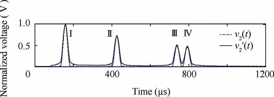
Fig.7 Envelops of v2(t)and obtained by LWSR(m=2)within 0-160 kHz and 0-100 kHz,respectively.
4.High-resolution damage imaging with LWSR
Associated with the classic delay-and-sum imaging algorithm,LWSR can be employed for high-resolution imaging of adjacent multiple damages.The basic imaging algorithm can be illustrated in Fig. 8, where the monitored structure is integrated with a sparse transducer array of Q (Q ≥3)PZT wafers. For a PZT pairj=1,2,···,Q)composed of Piat(xi,yi)and Pjat(xj,yj),the scattering propagation path with respect to an arbitrary point O at(x,y)can be geometrically determined.Assuming that only one Lamb wave mode exists with a constant group velocity cg0at the central frequency,the relevant time delay is

scattered from point O.All the scattered signals measured by PZT pairsare time-delayed and summarized to get an average energy at point O,that is,
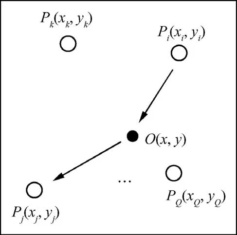
Fig.8 Illustration of delay-and-sum imaging algorithm.

With the energy E0(x,y)of each point normalized and greyscaled,a damage image over the whole structure can be generated.The local spots in the image with higher intensities will probably correspond to actual defects.
The delay-and-sum imaging method is a simple but effective method that can automatically focus the damage scattered signal measured by every PZT pair to any real flaw points.However,the imaging resolution could most-probably suffer from a poor signal spatial resolution caused by dispersion and a low ISR.In the LWSR-based imaging method,LWSR is firstly applied forduring damage imaging,and the pixel value at point O is calculated as


In Eq.(23),since each dispersive wavepacket inis compensated with its RD0simultaneously decreased by LWSR ina great enhancement for the resolution and performance of adjacent multiple damage imaging can be achieved.
5.Experimental validation
5.1.Experimental setup
To validate LWSR and LWSR-based imaging methods,an experiment of adjacent multiple damage imaging with A0mode Lamb waves is conducted on a 1000 mm×1000 mm×1.5 mm aluminum plate with material parameters given in Table 1.To monitor the entire plate,eight PZT wafers P1-P8(PSN-33,8 mm in diameter and 0.48 mm in thickness)are bonded to form a square transducer array,as shown in Fig.9.Four identical hexagonal hollow screws with a diagonal length of 8 mm,denoted as D1-D4,are successively mounted near each other on the plate to simulate adjacent damages.The exact positions of PZT wafers and damages in the orthogonal coordinate(see Fig.9)are listed in Table 2.
As illustrated in Fig.9,the overall experimental setup is composed of a Lamb wave detection system,a matrix switch controller,a power amplifier,and the aluminum plate.The Lamb wave detection system can generate Lamb wave signals and amplify and collect sensor signals.The matrix switch controller controls the working sequence of all PZT pairs,and the power amplifier is applied to amplify the excitation signal to enlarge the monitoring area in the plate.Practically,only a step pulse signal with a raising time of 0.25 μs is generated by the Lamb wave detection system to acquire the impulse response of each PZT pair with 20,000 points at 10 MHz.The narrowband excitation signal va(t)is a 3-cycle sine burst centered at 75 kHz,as shown in Fig.10.By convoluting the impulse response with va(t),a desired A0mode-dominated sensor signal is conveniently extracted.
5.2.Effect of LWSR
The efficiency of LWSR for A0mode dispersive sensor signals and damage-scattered ones is verified. From the impulse response h48(t)of PZT pair P4-8obtained with step pulse excitation in the healthy plate,as Fig.11(a)shows,the original sensor signal v048(t)under va(t)can be extracted.As Fig.11(b) illustrates, the dispersive A0mode direct arrival A is expanded in much more cycles with its time duration increased from 40 μs(see Fig.10(a))to about 90 μs,while the following boundary reflections denoted as B-L are severely superposed and hardly to be recognized.The spatial resolution of v048(t)is evidently influenced by severe dispersion effect and poor ISR.
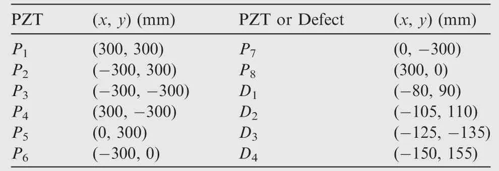
Table 2 The coordinates of PZTs and damages.
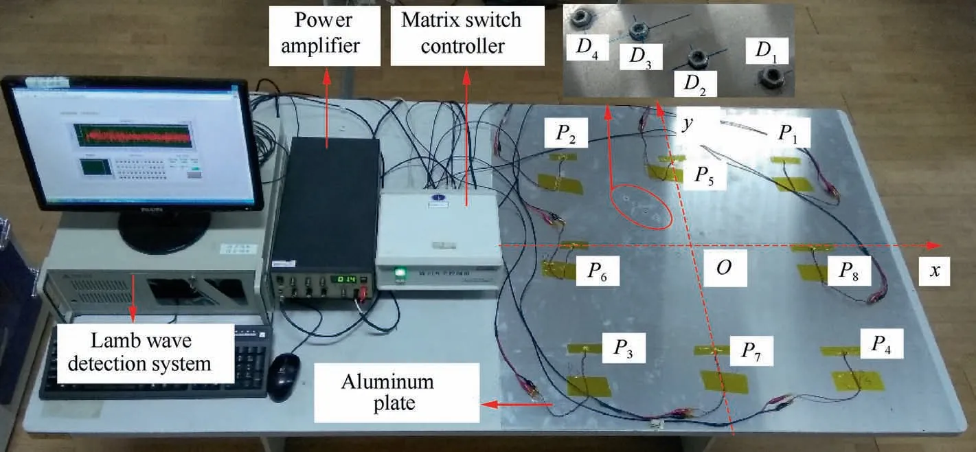
Fig.9 Experimental setup.

Fig.10 Narrowband excitation signal with a central frequency of 75 kHz.

Fig.11 Impulse response and original and LWSR-processed sensor signals of P4-8.

Fig.12 Theoretical A0 mode wavenumber relation K0(ω)in an aluminum plate with a thickness of 1.5 mm.
To enhance the signal resolution by LWSR,the A0mode theoretical wavenumber relation K0(ω)is firstly derived with the plate material parameters in Table 1,as Fig.12 shows.With the adjusting factor m set as 1 and 2.5 respectively for comparison, the linearized wavenumber curve K1(ω) or K2(ω)is computed from K0(ω)with Eqs.(8)and(11),as Fig.13(a)shows.Then,using Eq.(17),the mapping sequence Ω1(ω)or Ω2(ω)is decided with K1(ω)and K0(ω),K2(ω)and K0(ω) respectively, as illustrated in Fig. 13(b). Using Eq.(19),the LWSR(m=1)resultofwith Ω1(ω)is attained.As Fig.11(c)shows,all the dispersioncompensated A0mode wavepackets get fully recompressed.The first six boundary reflections B-G are well separated,whereas,due to the limited ISR with m=1,the neighboring boundary reflections H-I and J-L remain overlapped respectively,as illustrated by the dashed box in Fig.11(c).Much better improvement for the spatial resolution of v148(t) is demanded. Fig. 11(d) gives the LWSR result v248(t) of v048(t)with Ω2(ω).Since the ISR is improved to m=2.5 times,all the 12 recovered A0mode wavepackets A-L,including the previously-overlapped ones H-L within temporal intervals of 2250-2500 μs and 2650-3000 μs,get apart and can be easily distinguished at temporal sites corresponding to their time delays under the newly decreased group velocity at 75 kHz, cg1(75 kHz) =cg0(75 kHz)/2.5. The signal spatial resolution is sufficiently heightened by both dispersion compensation and cg1(75 kHz)reduction via LWSR with m=2.5.
For LWSR of all the damage-scattered signals,their corresponding impulse responses,as shown in Figs.14(a)and 15(a)for instance,should be obtained by subtracting the healthy impulse responses of all the PZT pairs from the damaged ones.The LWSR results of typical original scattered signals s018(t)andfrom different numbers of adjacent damages in P1-8are given in Figs.14 and 15,respectively.In s018(t)of dispersion and low ISR,the scattered wavepackets from D1and D2are badly overlapped,as Fig.14(b)shows.Even after dispersion removal by LWSR(m=1)without an ISR increase,the two recompressed scattered wavepackets in s118(t)are still mixed into a single one,as Fig.14(c)illustrates.Conversely,after LWSR with m=2.5,they are successfully separated in s218(t),as shown in Fig.14(d).

Fig.13 Linearized wavenumber curve K1(ω)or K2(ω)and interpolation mapping sequence Ω1(ω)or Ω2(ω)determined for LWSR with m=1 or m=2.5.
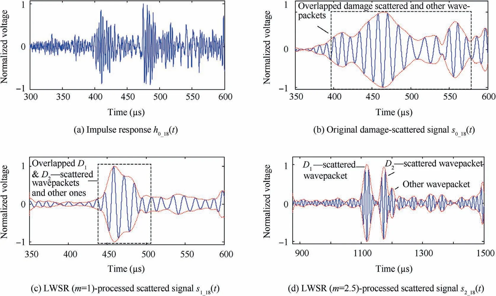
Fig.14 Results of LWSR(m=1 or m=2.5)of the original scattered signal s018(t)from D1-D2 with Ω1(ω)or Ω2(ω).
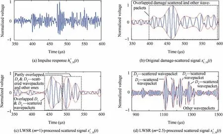
Fig.15 Results of LWSR(m=1 or m=2.5)of the original scattered signal from D1-D4 with Ω1(ω)or Ω2(ω).
When the four flaws D1-D4exist,their scattered wavepackets and other ones are completely or partly overlapped in the originalor its LWSR(m=1)result,as Figs.15(b)or 15(c)illustrates.Bothandof a limited ISR are subject to the inadequate spatial resolution and the resultant signal superposition.With m raised to 2.5 during LWSR,the four separated damage-scattered wavepackets distinctly emerge with restored waveforms and enough time space inas illustrated in Fig.15(d).Figs.14 and 15 demonstrate that the signal spatial resolution can be adequately heightened by LWSR with m=2.5, making information extraction for adjacent multiple flaws become an easy work.TDDM is performed for the original scattered signalsand.Similar to the LWSR(m=1)results(see Figs.14
In addition,to compare the performance of LWSR with those of other dispersion compensation approaches,the typical(c) and 15(c)), though all the dispersive damage-scattered wavepackets get well compensated and compressed in the TDDM-processed scattered signals,as Fig.16 shows,they keep grievously overlapped and interfere with each other,because of the insufficient ISR.

Fig.16 Results of TDDM of the original scattered signal s018(t)from D1-D2 or from D1-D4.
5.3.Results of damage imaging
By using the original,LWSR-,or TDDM-processed scattered signals measured by all the 28 PZT pairs,several images can be generated,respectively.For clearer illustration,only imaging results for the 400 mm×400 mm central zone of the plate are given in Figs.17 and 18,where every symbol‘‘X”denotes an actual damage position.Due to the poor spatial resolution of the scattered signals caused by dispersion and inadequate ISR(see Figs.14(b)and 15(b)),the diffused and blurred flaw spots in the images are combined together,leading to much difficulty for damage identification,as Figs.17(a)and 18(a)illustrate.In the LWSR(m=1)-based imaging results,as shown in Figs.17(b)and 18(b),the flaw spots get converged but still interfere with each other.Similar imaging results can be obtained with the TDDM-based imaging methods, as Figs.17(c)and 18(c)illustrate.This is because the scattered signals cannot bear a good enough spatial resolution just after dispersion removal(see Figs.14(c),15(c),and 16).In comparison,with both dispersion eliminating and ISR increasing actualized in the LWSR(m=2.5)-processed scattered signals(see Figs.14(d)and 15(d)),every defect can be expediently identified as a bright focalized spot without any interference,as illustrated in Figs.17(d)and 18(d).Only the satisfying imaging resolution and performance for different numbers of adjacent multiple damages can be achieved by the proposed imaging method based on LWSR with m=2.5.
6.Conclusions
(1)To solve the problem of inferior signal spatial resolution caused by dispersion and poor ISR in Lamb wave damage detection,LWSR is developed in this study.In LWSR,a linearly-dispersive version of an original Lamb wave signal is reconstructed with its group velocity adequately decreased at the central frequency,so that both dispersion compensation and ISR improvement can be realized to achieve a satisfying super signal spatial resolution.
(2)Associated with the delay-and-sum algorithm,LWSR is applied for high-resolution Lamb wave imaging of adjacent multiple damages.
(3)Experimental results prove that all the A0mode dispersive wavepackets in sensor signals or damage-scattered signals are properly recompressed to a pristine excitation waveform.Furthermore,with the adjusting parameter m raised from 1 to 2.5,the ISR is sufficiently heightened to successfully separate formerly compensated but superposed neighboring wavepackets at their arrival times corresponding to the newly decreased cg1=cg0/m.Using LWSR(m=2.5)-processed scattered signals with an adequate spatial resolution,different numbers of adjacent multiple damages can be successfully imaged and identified as bright focalized spots without any interference among them.
Acknowledgement
This study was supported by the Fundamental Research Funds for the Central Universities,China(No.NS2016012).
杂志排行
CHINESE JOURNAL OF AERONAUTICS的其它文章
- Guide for Authors
- Effect of W addition on phase transformation and microstructure of powder metallurgic Ti-22Al-25Nb alloys during quenching and furnace cooling
- Thermoelastohydrodynamic analysis of misaligned bearings with texture on journal surface under high-speed and heavy-load conditions
- Role of the inter-pass cooling rate in recrystallization behaviors of Ni-based superalloy during interrupted hot compression
- Crystal orientation and morphology of α lamellae in wrought titanium alloys:On the role of microstructure evolution in β processing
- Three-dimensional finite-time cooperative guidance for multiple missiles without radial velocity measurements
