柴油机催化型颗粒捕集器喷油助燃再生特征
2019-05-24陈朝辉孔孟茜赵罗峰包广元
张 韦,陈朝辉,孔孟茜,赵罗峰,包广元
柴油机催化型颗粒捕集器喷油助燃再生特征
张 韦,陈朝辉※,孔孟茜,赵罗峰,包广元
(昆明理工大学交通工程学院,云南省内燃机重点实验室,昆明 650500)
针对在用车辆的排放升级改造,以及满足非道路移动源四阶段排放标准限制要求,该文基于自主开发的喷油助燃主动再生系统,开展了加装DPF(diesel particulate filter)和不同CDPF(catalyzed diesel particulate filter)后处理器的发动机外特性试验和喷油助燃主动再生燃烧试验。结果表明:催化剂负载量为530 g/m3的CDPF,对外特性下发动机的动力性和经济性影响较小,并为碳烟再生提供了充足的NO2组分,因而其最大排气压差比DPF低8.8 kPa。630 ℃时无二次供气的CDPF其再生效率高达96.4%,载体最高温度比DPF低31 ℃;采用二次供气速率1.25 L/s、时长180 s,继续供气速率0.625 L/s、时长420 s的再生方案,600℃时CDPF的再生效率为83.2%,载体最高温度比无二次供气时降低了64 ℃;进行停机再生与怠速再生时,催化剂负载量为530 g/m3的CDPF具有更好的再生特性,其停机再生效率为76.4%,怠速再生效率达到88.5%。本研究对开发安全、高效的主动再生系统具有借鉴意义,并可为催化条件下的主动再生策略研究提供数据支撑。
柴油机;燃烧;催化剂;再生; DPF;CDPF;喷油助燃;台架试验
0 引 言
柴油机具备动力性强、经济性好和热效率高等优点,被广泛应用于以农业机械和工程机械为代表的非道路移动机械[1]。但由于柴油机的PM排放较高,且非道路移动机械的保有量逐年持续增加[2],因此所产生的PM排放问题日益突出。而DPF(diesel particulate filter)可有效捕集与去除PM,但要维持捕集器的持续、高效捕集,需对捕集器内的碳烟进行适时再生,常用的再生方式包括基于热管理的主动再生[3],以及涂覆催化剂的被动再生[4]。Kazuhiro Yamamoto[5]、Bai Shuzhan[6]等对催化再生PM的研究结果表明,被动再生热负荷小,无需额外耗能,但非道路柴油机的工作条件恶劣,且工况运行范围较宽,排气温度及成分波动大[7],难于保证各工况下都能实现较高的再生效率。主动再生则是通过氧化催化器或燃烧器氧化碳氢燃料[8],快速提升排气温度起燃再生PM。部分学者对PM的主动再生过程开展了试验与仿真计算研究[9-12],王建等[13]对DPF主动再生温度需求的柴油机进气节流控制策略开展了试验测试,Waldermar Karsten等[14]对喷油助燃再生燃烧器的结构进行了数值模拟,Eric Hein等[15-16]开展了发动机缸内远后喷及排气管后喷燃料的试验研究。Meng Zhongwei等[17]的试验结果发现,主动再生时在高温燃气的作用下,将在载体内形成大梯度温度分布,局部最高温甚至超过1 000 ℃。因此,需要将主、被动2种再生方式进行相互融合、取长补短,才能实现安全可靠的高效率再生[18]。然而,目前对基于DPF和CDPF(catalyzed diesel particulate filter)的喷油助燃主动再生方面的台架试验还比较欠缺,本文基于自主开发的主动再生燃烧系统,开展DPF和CDPF的主动再生燃烧特性试验研究,以期为在用车辆的排放升级改造及非道路移动机械实现第四阶段排放标准提供参考。
1 试验系统
试验测试的发动机为D30TCI型四缸直列高压共轨柴油机,符合国Ⅳ排放标准,DPF与CDPF在发动机台架中的安装位置见图1,发动机的主要技术参数见表1。测试用的DPF、CDPF1和CDPF2的具体参数见表2,其催化剂负载量分别为0、530和636 g/m3。DOC(diesel oxidation catalyst)的催化剂负载量为883 g/m3,DOC与CDPF的贵金属催化剂Pt与Pd的配比均为5∶1。测试设备主要有WE31水力测功机、FCM油耗仪、Testo 350气体分析仪、AVL4000烟度计、PTQ-A20精密电子称、温度及压力传感等。
本文首先对发动机原机、发动机分别加装DOC+DPF、DOC+CDPF1和DOC+CDPF2开展了外特性稳态试验,测试转速范围为1 200~3 000 r/min,每200 r/min测试1次。每个工况运行5 min,待柴油机运行稳定后测量其动力性、经济性参数,并分别采集DOC+DPF、DOC+CDPF和DOC+CDPF2前后端的排气温度、排气压力及排放参数。在外特性试验基础上,进一步开展喷油助燃主动再生试验,测试载体温度、积碳量、再生碳烟量等参数。

1. 喷射控制单元 2. 空气泵 3. 单向阀 4. 油泵 5. 油箱 6. 电源 7. 电磁油量阀 8. 点火棒 9. 燃烧器 10. DPF和CDPF
1. Dosing control unit 2. Air pump 3. Check valve 4. Oil pump 5. Oil tank 6. Power supply 7. Electromagnetic oil valve 8. Ignition stick 9. Burner 10. DPF and CDPF
注:P1、P2为DPF/CDPF的前、后端压力,kPa;T1、T2为DPF/CDPF的前、后端温度,℃。
Note: P1 and P2 are the pressure of before and after DPF/CDPF, kPa; T1 and T2 are the temperature of before and afte DPF/CDPF, ℃.
图1 柴油机台架测试系统
Fig.1 Diesel engine bench test system

表1 D30TCI柴油机的主要技术参数

表2 DPF、CDPF1和CDPF2的具体参数
2 发动机外特性对比
发动机原机、加装后处理器的外特性试验结果见图2。从图2a可知,CDPF2在1 200 r/min时发动机动力下降12.2%,燃油消耗率增加12.3%,而CDPF1的影响则较小,这是由于CDPF2比CDPF1的催化剂负载量高,加大了载体的压力损失,导致缸内燃烧变差。因此,随着转速上升,CDPF1和CDPF2对动力性与经济性的影响均变小,3 000 r/min时对2者的影响均小于1%。由图2b可知,由于CDPF1和CDPF2均比DPF的再生速率高,2者压差变化不大,与DPF相比载体内残余碳烟量较少,因而最大排气压差比DPF低8.8 kPa。
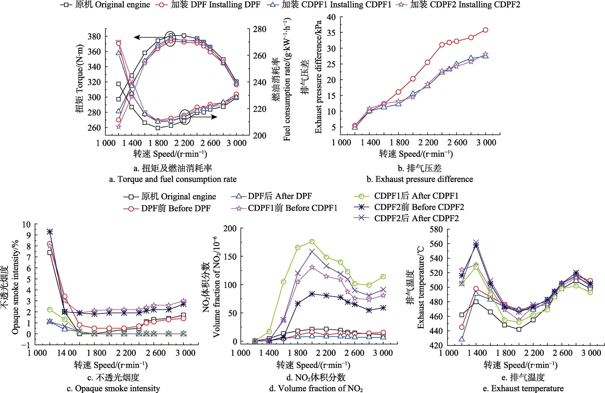
图2 发动机的外特性对比
根据图2c可知,发动机在1 200 r/min时不透光烟度较高,而在1 600~3 000 r/min时由于原机的不透光烟度较小,排气流经DPF、CDPF1和CDPF2后,不透光烟度几乎都小于1。如图2d,原机排放的NO2通过DPF后参与了碳烟氧化,因此DPF后端的NO2体积分数低于原机。由于前端DOC负载有较大量的贵金属催化剂,这提高了NO催化氧化为NO2的表面反应速率[4,9],因而也为CDPF提供了充足的NO2组分。3 000 r/min时CDPF1前端的NO2体积分数为81×10-6,后端较前端增加了33×10-6,而CDPF2后端则较前端增加了32×10-6。这说明在DOC与CDPF内,在Pt、Pd双金属催化剂的作用下,NO与排气O2的结合速率高于NO2解离产生活性氧与碳烟活性位的结合速率。由此可见,在外特性工况下,采取DOC+CDPF1的方案,既对发动机动力性与经济性影响较小,还能为CDPF1内碳烟的再生提供充足的NO2组分,不必采用具有较高贵金属负载量的CDPF2。
如图2e,大部分外特性工况下,DPF后端温度略低于前端,这是因为无催化剂时,柴油机的排温难以达到碳烟的起燃温度,且载体存在传热失所导致。1 200与1 400 r/min时,CDPF1和CDPF2的后端温度均低于前端,而在1 600~3 000 r/min时,后端温度略高于前端,这是由于在此转速范围时,虽然载体前端的排温(约为498~520 ℃)已达到了碳烟的催化起燃温度(约为450 ℃)[19],但载体内积累的碳烟量较少,导致放热量较低。
3 喷油助燃主动再生特性试验
3.1 喷油助燃主动再生试验方案
课题组自主开发了一套喷油助燃主动再生燃烧系统,该系统主要由油箱、油泵、电磁油量阀、二次空气泵、燃烧器、线束及喷射控制单元DCU(dosing control unit)、电瓶等组成,如图3所示。试验方案主要由2部分组成,第一部分试验在燃烧试验台上进行,试验前将DPF和CDPF1分别加装到发动机排气管路进行碳烟加载,碳载量为6 g/L。DPF和CDPF1的再生时长均为1 500 s,通过DCU控制燃烧试验温度分别为550 、600 和630 ℃。为防止再生时载体内的峰值温度与热应力过高,采取在喷油结束后进行持续供气(称为二次供气,喷油助燃再生时供给的空气称为一次供气)。基于二次供气量的大小与测试发动机排量相匹配的原则,采取4种不同的二次供气方案。方案1为无二次供气;方案2为二次供气速率0.625 L/s,时长300 s;方案3为二次供气速率0.625 L/s,时长600 s;方案4为二次供气速率1.25 L/s、时长180 s,继续供气速率0.625 L/s,时长420 s。试验前使用精密电子称称取新鲜件的质量记为,积碳和再生结束后,从排气管取下DPF和CDPF1,称取积碳后的载体质量记为1,称取再生后的载体质量记为2,即可得到积碳量和再生碳烟量。定义再生效率为,计算公式如式(1)。
第二部分试验在发动机测试台架上进行,仍采取在排气系统进行碳加载,加载工况为1 200 r/min、100%负荷,积碳时长1 200 s,然后开展喷油助燃再生试验。由于在用车辆的排放升级改造和非道路移动机械实现第四阶段排放标准,均会采用停机喷油再生和怠速再生2种方式,因此,本文测试了这2种方案的再生特性。停机喷油主动再生即发动机停机,依靠主动再生系统二次供气燃烧产生的高温,氧化再生碳烟(简称停机再生)。发动机怠速工况再生即发动机处于怠速工况,依靠发动机排气结合二次供气,进行喷油助燃主动再生(简称怠速再生)。停机再生和怠速再生后,对DPF、CDPF1和CDPF2进行3 000 r/min、100%负荷工况下的再生效果评价。
1. 喷射控制单元 2. 空气泵 3. 单向阀 4. 油泵 5. 油箱 6. 电源 7. 电磁油量阀 8. 点火棒 9. 燃烧器 10. DPF/CDPF
1. Dosing control unit 2. Air pump 3. Check valve 4. Oil pump 5. Oil tank 6. Power supply 7. Electromagnetic oil valve 8. Ignition stick 9. Burner 10. DPF/CDPF
a. 喷油助燃主动再生试验装置示意图
a. Schematic diagram of fuel injection combustion active regeneration system
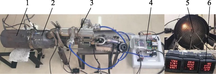
1. DPF和CDPF 2. 燃烧器 3. 旁通管 4. DCU 5. 热电偶 6. 数显仪表
1. DPF and CDPF 2. Burner 3. Bypass pipe 4. DCU 5. Thermocouples 6. Digital display meter
b. 喷油助燃主动再生试验台
b. Fuel injection combustion active regeneration test bench
图3 喷油助燃主动再生试验系统
Fig.3 Fuel injection combustion active regeneration testing system
3.2 测试结果与分析
图4为不同再生温度时DPF和CDPF1的主动再生效率及载体的最高温度。分析图4a可知,随着再生温度升高,DPF与CDPF1的再生效率都有所上升。DPF在550 ℃的再生效率仅为43.8%,630 ℃的再生效率达到84.3%。CDPF1在600 ℃时的再生效率为89.7%,而630 ℃的再生效率达到96.4%。CDPF1在3个温度下的再生效率都较DPF高,这是由于在Pt、Pd双金属催化剂的作用下,不但提高了碳烟的起燃活性,还提升了O2的吸附量与迁移到碳烟表面的速率[20-22]。从图4b可以看出,由于CDPF1内的碳烟起燃温度较低[23-25],载体内的温度上升速率较快,但载体的最高温度却较DPF低。再生温度为600 ℃时,CDPF1载体的最高温度比DPF低约35 ℃,630 ℃时的最高温比DPF低约31 ℃。由此可见,CDPF1不仅能提高再生效率,还能降低载体内的最高温度。
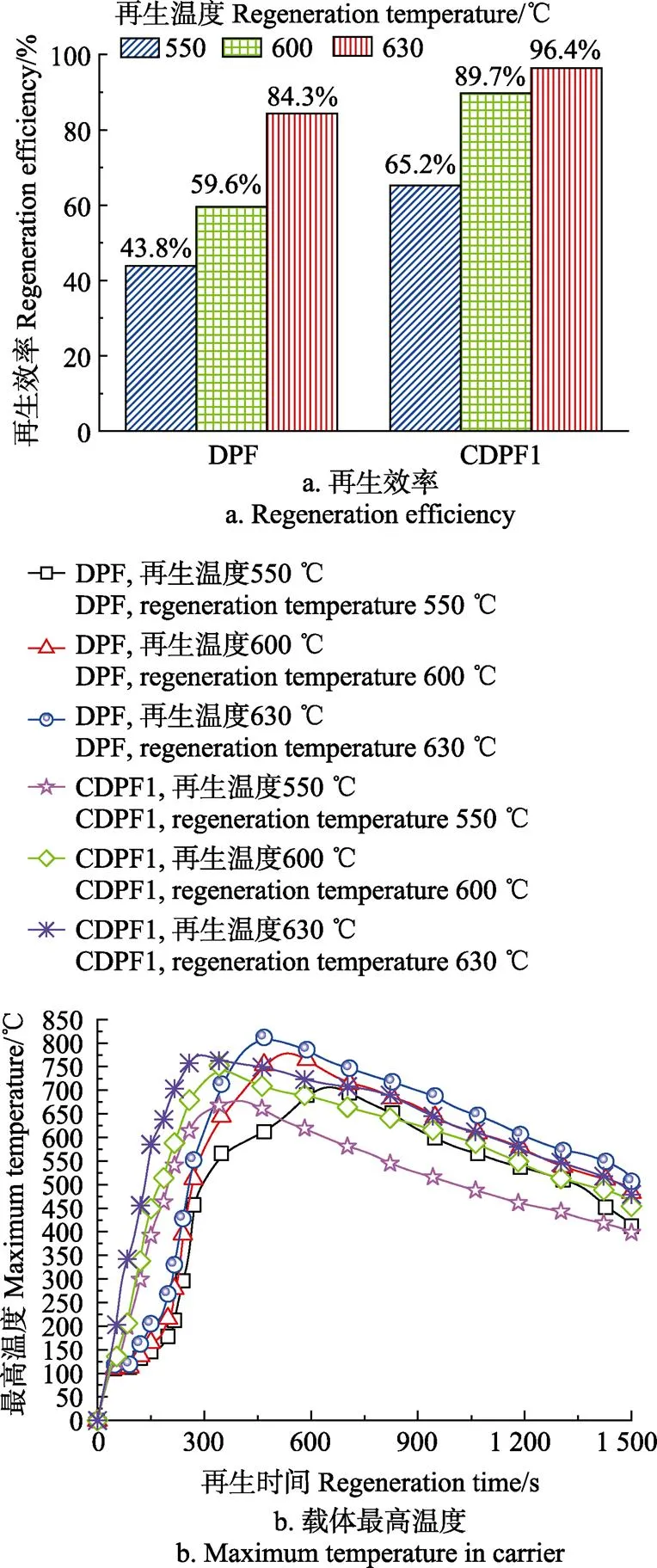
图4 不同再生温度时的再生效率及载体的最高温度
图5为不同二次供气条件下DPF和CDPF1的再生效率及载体的最高温度对比。分析图5a可知,DPF采用二次供气方案2比方案1的再生效率低2.8个百分点,而方案4比方案1低5.5个百分点。CDPF1采用方案2的再生效率为85.4%,比方案1的再生效率低4.3个百分点,而采用方案4的再生效率为83.2%,比方案1低6.5个百分点。分析图5b可知,DPF和CDPF1采用方案4时,载体最高温度降低幅度最大,DPF最高温度降低约53 ℃,CDPF1降低约64℃。由此可见,先采用短时长、大流量的二次供气,能加快载体的散热速率,虽然初始阶段温度降低迅速,但O2组分的传质速率增加;继而再采用较小流量、较长时长的二次供气策略,确保了载体再生所需温度,因此对再生效率的影响较小。所以采用方案4的二次供气策略,CDPF1的再生效果较好,再生效率下降幅度较小,载体最高温度降低幅度较大,这将有助于提高载体在实车应用中的安全性与可靠性。

图5 不同二次供气方案的再生效率及载体的最高温度
3.3 停机与怠速喷油再生试验结果与分析
3.3.1 停机再生与怠速再生的温度对比
图6为停机与怠速再生时,载体的入口与出口排气温度。从图6a可知,喷油助燃再生开始后,通过DCU控制燃油喷射,燃烧器点火燃烧,入口温度迅速上升到600 ℃并持续保持480 s,DCU切断燃油喷射,采用二次供气方案4直到1 100 s再生结束。由于本文试验用碳化硅载体的导热系数较高,并且考虑到再生过程中载体的安全性,DPF碳载量为4.6 g/L,CDPF1和CDPF2的碳载量均为2.2 g/L。当600 ℃的高温燃气进入载体后,虽然会燃烧碳烟释放热量,但由于传热过程损失了部分热能[26-28],第600 s时CDPF1的出口温度比入口温度低约199 ℃。怠速再生时,由于具有较高温度的发动机排气进入燃烧器,高温废气与二次空气配合,在载体内会蓄积更多热量的燃气,引发了碳烟的快速再生并释放了更多的热量。因此,怠速再生时载体出口温度都较停机再生的高。此外,CDPF1较CDPF2将碳烟燃烧的速率快,因而其载体出口的温升速率也较CDPF2上升迅速,CDPF1在600 s时出口温度约为445 ℃,而CDPF2在750 s时才上升到相同温度。

图6 停机再生与怠速再生的载体入口与出口温度
3.3.2 停机再生与怠速再生的碳烟量对比
图7为停机再生与怠速再生时,DPF、CDPF1和CDPF2的2次积碳量及再生效率对比。从图7可知,当积碳温度为427 ℃时,DPF第1次积碳量为19 g,停机再生效率为48.9%,经过第2次积碳后进行怠速主动再生的效率为73.3%。CDPF1和CDPF2的停机与怠速再生效率都较DPF高,CDPF1的停机再生效率为76.4%,而怠速再生效率增加到88.5%。CDPF2的2次再生效率较CDPF1低,其停机再生效率为71%,怠速再生效率为83.8%。通过以上分析可知,载体的怠速主动再生效率均高于停机再生,这是由于停机再生是冷态二次空气进入燃烧器,而怠速再生是将具有较高温度的发动机废气引入燃烧器,在二次空气的配合下,既提高了燃油在燃烧器内的燃烧速率,同时高温燃气会以更快的速率燃烧更多的碳烟,从而提高了怠速主动再生的燃烧效率。基于喷油再生的试验结果,说明通过DCU控制燃烧器的温度为600 ℃,采取方案4的二次供气策略,能确保载体的安全可靠再生,使用贵金属负载量较低的CDPF1,在停机与怠速再生时,都能具有较高的再生效率。
3.3.3 停机再生与怠速再生后压差与温度的评价对比
图8是开展停机再生和怠速再生结束后,在3 000 r/min、100%负荷工况下DPF、CDPF1和CDPF2的压差对比。结合图6~8可知,由于更多的高温燃气产生了较高的再生效率,怠速再生后载体内残余的碳烟量更少,因而怠速再生后的压差都较停机再生低。DPF停机再生后的压差在32 kPa上下波动,怠速再生后压差下降到28 kPa左右。CDPF1停机再生后的压差约为27 kPa,怠速再生后的最终压差降低到25 kPa。CDPF2停机再生后最终压差约为24.5 kPa,怠速再生后的压差下降到22 kPa。

图7 停机再生与怠速再生效果

图8 停机再生和怠速再生后的压差对比
图9为停机再生和怠速再生后,在3 000 r/min、100%负荷工况下,DPF、CDPF1和CDPF2的温度对比。在初始时刻,停机再生后CDPF1的入口温度为466 ℃,CDPF2的温度为405 ℃,怠速再生后CDPF1入口温度上升到469 ℃,CDPF2的则增加到441 ℃,DPF也具有同样的变化规律。这是由于怠速再生后载体的排气压差较小,引起发动机缸内燃烧压力和燃烧温度增加[29],排气温度上升,因此怠速再生后载体入口端的温度较高,但入口温度都达到了碳烟被动再生的起燃温度。由此说明,采取催化型CDPF进行主、被动相结合的再生方式,能将2者的优点进行相互融合,在未来的研究中,通过进一步优化催化负载量、再生时机,同时结合排气热管理等技术[30],将有助于形成基于催化条件下的主动再生策略。
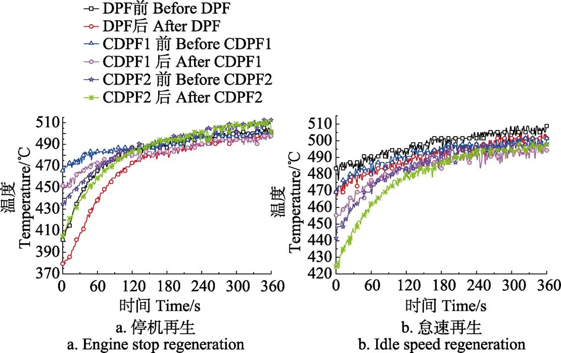
图9 停机再生和怠速再生后的温度对比
4 结 论
1)外特性试验中,采用催化剂负载量为530 g/m3的CDPF,在Pt、Pd双金属催化剂的作用下,能为被动再生提供充足的NO2组分,因此,CDPF的最大排气压差比DPF低8.8 kPa。加装CDPF对发动机的动力性与经济性影响较小,3 000 r/min时对动力性与经济性的影响均小于1%。
2)基于自主开发的主动再生燃烧系统,开展喷油助燃再生燃烧试验。通过ECU控制燃烧温度为600 ℃,采取4种不同的二次供气方案,催化剂负载量为530 g/m3的CDPF,采用二次供气速率1.25 L/s、时长180 s,继续供气速率0.625 L/s、时长420 s的方案时,再生效率达到83.2%,比无二次供气时载体的最高温度降低了64 ℃。说明采用上述二次供气方案再生效果较好,这将有助于实现载体在实车应用中进行安全、可靠的高效率再生。
3)在停机与怠速再生试验中,采取二次供气速率1.25 L/s、时长180 s,继续供气速率0.625 L/s、时长420 s的方案,再生时长为1 100 s。试验结果表明,催化剂负载量为530 g/m3的CDPF具有较好的再生效果,其停机再生效率为76.4%,怠速再生效率达到88.5%。
未来的研究可通过进一步优化催化负载量、再生时机,同时结合排气热管理等技术,形成基于催化条件下的主动再生策略,为在用车辆的排放升级改造及非道路移动机械实现第四阶段排放标准提供参考。
[1] 谭丕强,王德源,楼狄明,等.农业机械污染排放控制技术的现状与展望[J]. 农业工程学报,2018,34(7):1-14. Tan Piqiang, Wang Deyuan, Lou Diming, et al. Progress of control technologies on exhaust emissions for agricultural machinery[J]. Transactions of the Chinese Society of Agricultural Engineering (Transactions of the CSAE), 2018, 34(7): 1-14.(in Chinese with English abstract)
[2] Fu Mingliang, Ge Yunshan, Tan Jianwei, et al.Characteristics of typical non-road machinery emissions in China by using portable emission measurement system[J]. Science of the Total Environment, 2012 , 437(20): 255-261.
[3] Bai Shuzhan, Chen Guobin, Sun Qiang, et al. Influence of active control strategies on exhaust thermal management for diesel particular filter active regeneration[J]. Applied Thermal Engineering, 2017(119): 297-303.
[4] 黄河,孙平,刘军恒,等. 纳米CeO2催化剂对柴油机碳烟颗粒和NO降低效果[J]. 农业工程学报,2017,33(2):54-59. Huang He, Sun Ping, Liu Junheng, et al. Reducing soot and NO emission from diesel engine exhaust catalyzed by nano- CeO2[J]. Transactions of the Chinese Society of Agricultural Engineering (Transactions of the CSAE), 2017, 33(2): 54-59. (in Chinese with English abstract)
[5] Kazuhiro Yamamoto, Tatsuya Sakai. Simulation of continuously regenerating trap with catalyzed DPF[J].Catalysis Today, 2015(242): 357-362.
[6] Bai Shuzhan, Tang Jiao, Wang Guihua, et al. Soot loading estimation model and passive regeneration characteristics of DPF system for heavy-duty engine[J]. Applied Thermal Engineering, 2016(100): 1292-1298.
[7] E Jiaqiang, Zuo Wei, Gao Junxu, et al. Effect analysis on pressure drop of the continuous regeneration-diesel particulate filter based on NO2assisted regeneration[J]. Applied Thermal Engineering, 2016(100): 356-366.
[8] Dieter Rothe, Markus Knauer, Gerhard Emmerling, et al. Emissions during active regeneration of a diesel particulate filter on a heavy duty diesel engine: Stationary tests[J]. Journal of Aerosol Science, 2015(90): 14-25.
[9] Chen Pingen, Wang Junmin. Air-fraction modeling for simultaneous Diesel engine NOx and PM emissions control during active DPF regenerations[J]. Applied Energy, 2014, 122(5): 310-320.
[10] Deng Yuanwang, Zheng Wenping, E Jiaqiang, et al. Influence of geometric characteristics of a diesel particulate filter on its behavior in equilibrium state[J]. Applied Thermal Engineering, 2017(123) :61-73.
[11] 伏军,龚金科,左青松,等. 微粒捕集器喷油助燃再生喷油与补气的优化控制[J]. 农业工程学报,2012,28(17): 11-18. Fu Jun, Gong Jinke, Zuo Qingsong, et a1. Optimum control of fuel injection and air supply for burner-type diesel particulate filter regeneration[J]. Transactions of the Chinese Society of Agricultural Engineering (Transactions of the CSAE), 2012, 28(17): 11-18. (in Chinese with English abstract)
[12] Hiroyuki Yamada, Satoshi Inomat, Hiroshi Tanimoto. Mechanisms of increased particle and VOC emissions during DPF active regeneration and practical emissions considering regeneration[J]. Environmental Science & Technology, 2017, 51(5): 2914-2923.
[13] 王建,曹政,张多军,等. 基于DPF主动再生温度需求的柴油机进气节流控制策略[J]. 农业工程学报,2018,34(2):32-37. Wang Jian, Cao Zheng, Zhang Duojun, et al.Intake throttling control strategy based on DPF active regeneration temperature for diesel[J]. Transactions of the Chinese Society of Agricultural Engineering (Transactions of the CSAE), 2018, 34(2): 32-37.(in Chinese with English abstract)
[14] Waldemar Karsten, Martina Goy, Heide Vom Schloss, et al. Diesel burner for particle filter regeneration at mobile machinery[J]. Mtz Worldwide, 2013, 74 (7/8): 18-22.
[15] Eric Hein, Adam Kotrba, Tobias Inclan, et al. Secondary fuel injection characterization of a diesel vaporizer for active DPF regeneration[J]. SAE Int. J. Engines, 2014, 7(3): 1228-1234.
[16] Chen Pingen, Umar Ibrahim, Wang Junmin. Experimental investigation of diesel and biodiesel post injections during active diesel particulate filter regenerations[J]. Fuel, 2014, 130(7): 286-295.
[17] Meng Zhongwei, Zhang Jing, Chen Chao, et al. A numerical investigation of the diesel particle filter regeneration process under temperature pulse conditions[J]. Heat and Mass Transfer, 2017, 53(5): 1589-1602.
[18] Kuwahara T, Nishii S, Kuroki T, et al. Complete regeneration characteristics of diesel particulate filter using ozone injection[J].Applied Energy, 2013, 111(11): 652-656.
[19] Keld Johansen. Multi-catalytic soot filtration in automotive and marine applications[J].Catalysis Today, 2015(258): 2-10.
[20] Herreros J M, Gill S S, Lefort I, et al.Enhancing the low temperature oxidation performance over a Pt and a Pt–Pd diesel oxidation catalyst[J].Applied Catalysis B Environmental, 2014 , 147(7): 835-841.
[21] Verónica Rico Pérez, Agustín Bueno-López. Catalytic regeneration of diesel particulate filters: Comparison of Pt and CePr active phases[J]. Chemical Engineering Journal, 2015(279): 79-85.
[22] Zdeněk Vít, Daniela Gulková, Luděk Kaluž, et al. Effect of catalyst precursor and its pretreatment on the amount of-Pd hydride phase and HDS activity of Pd-Pt/silica-alumina[J]. Applied Catalysis B: Environmental, 2014(146): 213-220.
[23] Zhou Qiuhong, Zhong Kunhua, Fu Weiling, et al. Nanostructured platinum catalyst coating on diesel particulate filter with a low-cost electroless deposition approach[J]. Chemical Engineering Journal, 2015(270): 320-326.
[24] Qi Guolu, Zhang Yexin, Chen Aibing, et al. Potassium- activated wire mesh: A stable monolithic catalyst for diesel soot combustion[J]. Chemical Engineering & Technology, 2016, 40(1): 50-54.
[25] Valeria Di Sarli, Gianluca Landi, Luciana Lisi, et al. Catalytic diesel particulate filters with highly dispersed ceria: Effect of the soot-catalyst contact on the regeneration performance[J]. Applied Catalysis B Environmental, 2016(197): 116-124.
[26] Galindo J, Serrano J R, Piqueras P, et al. Heat transfer modelling in honeycomb wall-flow diesel particulate filters [J]. Energy, 2012, 43(1): 201-213.
[27] Nepal C Roy, Akter Hossain, Yuji Nakamura. A universal model of opposed flow combustion of solid fuel over an inert porous medium[J]. Combustion & Flame, 2014, 161(6): 1645-1658.
[28] Chen Tao, Wu Zhixin, Gong Jinke, et al. Numerical simulation of diesel particulate filter regeneration considering ash deposit[J]. Flow Turbulence Combust, 2016, 97(3): 1-16.
[29] Yu Mengting, Dan Luss, Vemuri Balakotaiah. Analysis of flow distribution and heat transfer in a diesel particulate filter[J]. Chemical Engineering Journal, 2013, 226(24): 68-78.
[30] Eid S Mohamed. Experimental study on the effect of active engine thermal management on a bi-fuel engine performance, combustion and exhaust emissions[J]. Applied Thermal Engineering, 2016(106): 1352-1365.
Bench test of regeneration characteristics of catalyzed diesel particulate filter based on fuel injection combustion system
Zhang Wei, Chen Zhaohui※, Kong Mengxi, Zhao Luofeng, Bao Guangyuan
(650500,)
In order to provide technical references for upgrading emissions of existing vehicles, to meet the four-stage emission limitation requirements of non-road mobile machineries, based on the self-developed fuel injection combustion active regeneration system, the external characteristic tests of diesel engine with diesel particulate filter(DPF) and the active regeneration combustion tests were carried out in this paper. The results showed that the catalyzed diesel particulate filter (CDPF) with 530 g/m3catalysts loading, name as CDPF1, has little effect on the power and economy performances of the engine under external characteristic conditions. At 3 000 r/min, the volume fraction of NO2is 81×10-6at front end of CDPF1, while it is increased by 33×10-6at rear end of that. This indicates that with the action of Pt and Pd bimetallic catalysts, the binding rate of NO to exhaust O2is higher than the rate of active oxygen dissociated from NO2binding to the soot active sites. Adequate NO2content promotes regeneration efficient of soot in the CDPF, therefore the maximum exhaust pressure difference of CDPF1 was 8.8 kPa which lower than that of DPF. On the basis of external characteristic tests, the active regeneration tests of fuel injection combustion was further carried out. The first part of the regeneration tests were carried on the combustion test bench, the combustion temperatures were controlled by dosing control unit (DCU) to be 550, 600 and 630 ℃, respectively. In order to prevent the peak temperature and thermal stress in the carrier from being too high during regeneration, secondary gas supply was carried out after fuel injection. Based on the principle that the amount of the secondary gas supply matches with displacement of the test engine, 4 different secondary gas supply schemes were adopted. The experimental results showed that when the regeneration temperature was 630 ℃, the regeneration efficiency of CDPF1 reached 96.4% in the absence of secondary gas supply, however, the regeneration efficiency of DPF was only 84.3%. In addition, the maximum temperature of CDPF1 carrier was also lower than that of DPF during regeneration, and the highest temperature of CDPF1 was about 31 ℃which lower than that of DPF at 630 ℃. It can be seen that CDPF1 could not only improve the regeneration efficiency, but also reduce the maximum temperature in the carrier. When regeneration temperature was 600 ℃, the secondary gas supply scheme 4 was adopted, i.e. the secondary gas supply rate was 1.25 L/s for 180 s, then the gas supply rate was 0.625 L/s for 420 s, and the regeneration efficiency of CDPF1 was 83.2%, the maximum temperature was reduced by about 64 ℃ compared to the absence of secondary gas supply. The second part of regeneration tests were carried out on engine test bench, and the regeneration temperature was still 600 ℃. The regeneration characteristics of DPF, CDPF1, CDPF2 and the CDPF2 with 636 g/m3catalysts loading were tested under engine stop and idle speed regeneration conditions. The test results showed that CDPF1 had a good regeneration performance, with regeneration efficiency was 76.4% for engine stop regeneration, the idle regeneration efficiency was increased to 88.5%. This was because that the secondary air into the combustion chamber was cold for engine stop regeneration, and the engine exhaust with higher temperature was introduced into the burner for the idle regeneration, the secondary air was combined to improve the burning rate of the fuel in the burner, at the same time, high temperature gas would burn more soot at a faster rate, and the combustion efficiency of the idle condition regeneration was improved. The pressure difference of DPF, CDPF1 and CDPF2 was tesed under 3 000 r/min speed and 100% load conditions. Since the amount of residual soot in the carrier was less after the idle regeneration, the pressure difference of DPF, CDPF1 and CDPF2 after idle regeneration were lower than that of engine stop regeneration. The pressure difference of CDPF1 was about 27 kPa after engine stop regeneration, and the final pressure difference was reduced to 25 kPa after idle regeneration. This study showed that the combination of active and passive regeneration of catalytic CDPF can integrate the advantages of the both, in future research, the active regeneration strategy based on catalytic conditions can be formed by further optimizing the catalytic load and regeneration timing, combining with exhaust heat management technology, and provide a reference for the upgrading and transformation of exhaust emissions of vehicles in use and the realization of the fourth stage emission standards of non-road mobile machinery.
diesel engine; combustion; catalysts; regeneration; DPF; CDPF; fuel injection assisted combustion; bench test
2018-10-06
2019-01-18
国家自然科学基金资助项目(51666007;51665023)
张韦,博士,教授,主要从事内燃机燃烧与排放控制研究,Email:koko_575@aliyun.com
陈朝辉,博士,副教授,主要从事内燃机燃烧与排放控制研究。Email:chenzhaohuiok@sina.com
10.11975/j.issn.1002-6819.2019.08.011
TK411+.5
A
1002-6819(2019)-08-0092-08
张 韦,陈朝辉,孔孟茜,赵罗峰,包广元. 柴油机催化型颗粒捕集器喷油助燃再生特征[J]. 农业工程学报,2019,35(8):92-99. doi:10.11975/j.issn.1002-6819.2019.08.011 http://www.tcsae.org
Zhang Wei, Chen Zhaohui, Kong Mengxi, Zhao Luofeng, Bao Guangyuan. Bench test of regeneration characteristics of catalyzed diesel particulate filter based on fuel injection combustion system[J]. Transactions of the Chinese Society of Agricultural Engineering (Transactions of the CSAE), 2019, 35(8): 92-99. (in Chinese with English abstract) doi:10.11975/j.issn.1002-6819.2019.08.011 http://www.tcsae.org
