基于旋量理论的六自由度林果采摘混联机械臂运动学逆解
2019-05-24李立君高自成李禹卓许世斌
李立君,刘 涛,高自成,廖 凯,李禹卓,许世斌
基于旋量理论的六自由度林果采摘混联机械臂运动学逆解
李立君,刘 涛,高自成,廖 凯,李禹卓,许世斌
(中南林业科技大学机电工程学院,长沙 410000)
针对传统Paden-Kahan子问题求解机械臂运动学逆解时需确定关节轴线交点坐标的问题,对该子问题进行改进。利用末端执行器位姿信息获取轴线交点坐标,建立物体坐标与末端执行器期望位姿的映射关系,结合子问题求解6自由度林果采摘机械臂运动学逆解;根据主动关节变量取值范围分析所求逆解的可行性,得到可行封闭解,提高机械臂控制速度、稳定性和准确性。在实验室环境下利用所提出的算法求解10组工作目标位置信息对应的关节值,结果表明,所求逆解能使林果采摘机械臂到达正确位姿,末端执行器最大位置误差不超过夹持器最大开度的3.30%,最大姿态误差不超过1°,满足采摘要求。该算法为机械臂快速、稳定及精确地控制提供技术依据。
机器人;收获机;运动学;旋量理论;逆运动学;Paden-Kahan子问题;混联机械臂;林果采摘
0 引 言
机械臂逆运动学求解方法常与正运动学建模方法有关。目前机械臂运动学建模主要使用Denavit-Hartenberg(D-H)参数法、旋量法与四元数法,并有相应的逆运动学求解方法[1-4]。若基于旋量理论建立正运动学模型,则常用Paden-Kahan子问题求解。Paden-Kahan子问题由Paden基于指数积公式提出[5],该算法利用特殊点消去运动学模型中的部分关节变量,使整个逆运动学分析过程分解成若干子问题,所得子问题具有明确的几何意义且能有效避免引入局部坐标系所带来的奇异性[6-7],从而简化求解。根据不同划分,可得到不同子问题组合,因此Paden-Kahan子问题算法相对其他算法有较大灵活性。除此之外,运用Paden-Kahan子问题求机械臂运动学逆解还具有计算速度快、数值解稳定的优点[8-9]。因此,本文使用Paden-Kahan子问题分析林果采摘混联机械臂逆运动学问题。Murray等对子问题进行了整理,提出了6类子问题[10],并给出了其中最典型3类的解法。
国内外已有学者对Paden-Kahan子问题在串、并联机械臂运动学逆解方面的应用进行了研究[11-13]。Sariyildiz等[14]将四元数与子问题算法相结合,对6R串联机器人进行运动学逆解分析,并与D-H法做对比。结果表明Paden-Kahan子问题的求解速度比传统D-H参数法快一倍。Gao等[15]利用经典子问题对蟑螂仿生机器人逆运动学进行了求解,并给出了直线行走和定点旋转运动的关节运动路径,通过试验验证了Paden-Kahan子问题的精确性。陈庆诚等[16]针对3条不相交的关节轴线提出了一种新的子问题,对其进行求解并应用于6R串联机器人逆运动学分析,在一定程度上扩大了子问题应用范围。Wang等[17]通过代数方法解决了2关节轴线互异的子问题2(即刚体依次绕2轴分别旋转2个角度得到新的位置,求解子问题2即是求解这两个角度。经典Paden-Kahan子问题2必须要求两轴相交),使子问题2求解对象扩展至任意两相邻旋转关节,并对5R串联机器人进行了逆运动分析。试验和仿真结果表明利用改进Paden-Kahan子问题算法求解精度是径向基函数神经网络(radial basis function neural network,RBFNN)算法的5倍,求解速度比RBFNN算法快4倍。
结合上述文献,发现旋量理论在机械臂运动学逆解问题的应用中还存在以下问题:1)研究对象主要为串联或并联机械臂,旋量理论在混联机械臂的运动学逆解问题的应用较少,仅通过单一的方法无法求得混联机械臂运动学逆解。2)求解过程中常运用旋转运动不改变旋转轴上点位置的原理利用腕关节位置矢量化简运动学方程组,但腕关节位置矢量本就是未知量,上述文献并未给出有效的解决方法。3)求解时并未考虑关节变量取值范围,致使本来为高度非线性的运动学逆解问题引入非必要的运算,降低机械臂运动控制算法的运行效率。
为增强Paden-Kahan子问题在机械臂控制上的实用性,结合混联林果采摘机械臂特点,本文将其混联结构等效转化为串联结构;推导机械臂位姿与腕关节位置的关系,结合Paden-Kahan子问题算法求解6自由度混联机械臂运动学逆解;根据关节空间范围分析得到可行封闭解;根据机采摘机械臂工况,建立目标位姿与机械臂期望位姿映射以获取物体坐标到关节空间的完整对应关系;最后开展试验验证所提方法的正确性与精确性。以期为对机械臂进行轨迹规划、运动控制和动力学分析提供参考。
1 林果采摘机械臂及旋量运动模型
1.1 旋量理论与刚体运动
旋量是一个几何实体,通过旋量坐标能描述任何绕某一轴旋转和沿该轴移动的合成运动[18-19]。Chalse已证明刚体运动能分解为上述合成运动[10],即旋量运动。旋量坐标由特殊欧式群的李代数se(3)的6×1向量形式表示,具体表达式如下[20-21]
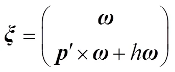
式中为6×1旋量坐标,为旋量轴线的方向余弦,¢为旋量轴线上任选一点¢的位置矢量,为旋距。
当关节为转动副时,=0;当关节为移动副时,趋于无穷大。在这2种极端情况下,旋量坐标对应李代数se(3)的标准4×4矩阵形式表示为

旋量坐标可以通过如下步骤确定:
1)选择一个合适的结构参考位形。
2)确定此位形下每个关节轴线的方向余弦矢量及轴线上任选点¢的位置矢量¢。
3)根据关节运动类型,由式(2)计算旋量坐标。
刚体从位形一次运动到位形的仿射矩阵由指数映射给出[10]:

式中为4×4单位矩阵,为关节变量值,为展开阶数。
式(3)说明了一次刚体运动由表示运动方向的和表示沿该方向的运动量组成。若刚体连续做多次螺旋运动,经由个关节串联成的运动链从位形运动到位形,则这一系列的刚体运动用指数积公式(product of exponential,POE)描述[22]:

林果采摘机械臂结构简图与参考位形如图1所示,对机械臂主运动链使用指数积公式可以得到其末端位姿为[23]

本文所用正运动学模型建立在文献[23]研究基础之上,具体正运动学建模过程可参考文献[23]。
1.2 机械臂结构分析
如式(5)所示,机械臂主运动链有8个活动关节,而机械臂自由度为6。为简化求解过程,可将其并联移动结构等效为串联转动结构,因此需通过分析其几何特征获得主动移动关节与被动转动关节之间关系。机械臂结构参数如表1所示:
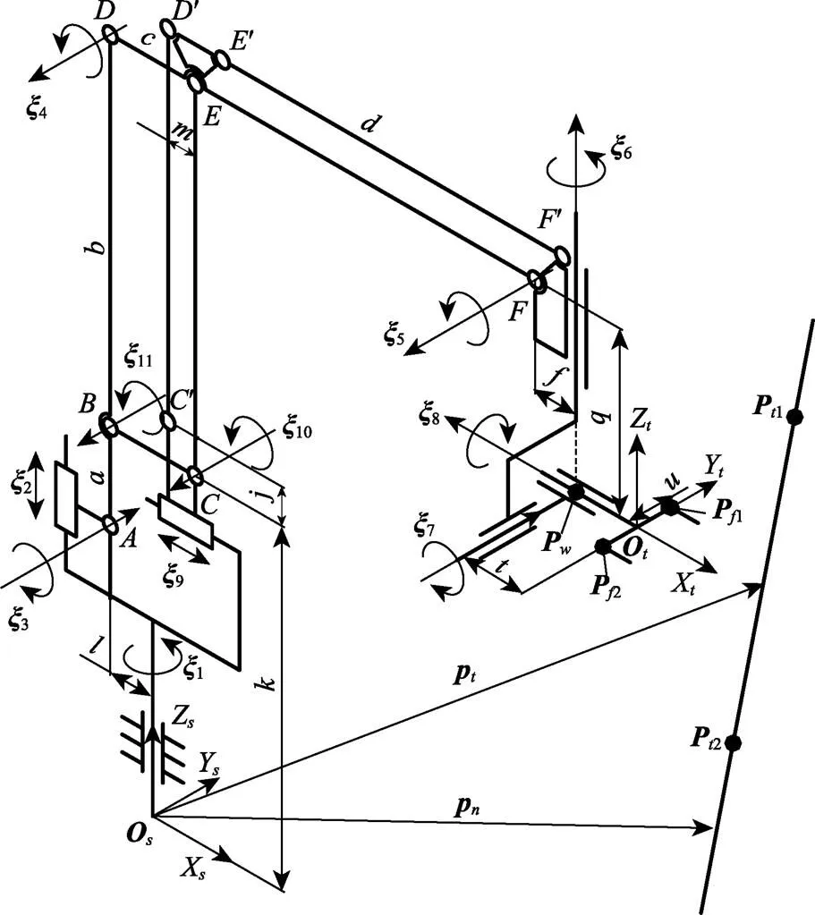
注:ξi为第i轴运动旋量坐标(i=1,2,…,11);A为连杆铰接点,a为连杆长度或杆间距,mm;其余同理;Os–XsYsZs为基础坐标系;Ot–XtYtZt为末端执行器坐标系;Pw为腕关节点;Pf1和Pf2为指关节点;Pt1和Pt2为工作目标上的标记点;pt为工作目标位置矢量;pn为垂直于工作目标标线的位置矢量;如无特殊说明,后文均使用P表示刚体上的点,p表示该点的位置矢量,不同点通过下标区分。
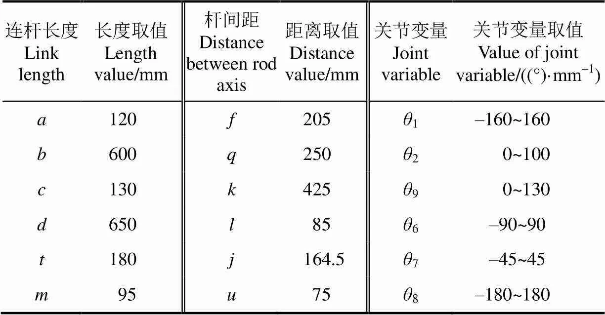
表1 机械臂结构参数
注:θ表示沿方向的运动量(=1,2,6,7,8,9)。
Note:θrepresents the distance of rigid body motion along, (=1,2,6,7,8,9).
结合图1可知,、¢¢及¢¢为3个平行四边形。对于平行四边形结构,其连杆上4个关节所转过角度相同,于是有:


表2 机械臂在参考位形下的旋量参数
依次选取点和点为结点,由指数积公式(4)得到结构方程:


前3个方程组相互独立,解得:


2 逆运动学求解
2.1 求解θ1、θ2与θ9
逆运动分析解决的问题是根据末端执行器的期望位姿来获得一组或若干组关节变量,从而控制末端执行器到达该位姿。因此末端执行器位姿矩阵是已知的:

式中(=1,2,3)为末端执行器方向余弦,为末端执行器位置矢量。
根据旋量代数的基本性质,当旋矩=0时,若在关节轴线上取一点,旋转作用对该点无效,即:


为求解上式,需先获得点的坐标,但在实际控制中,已知的只有末端执行器位姿,腕关节位置无法直接获取,从而对求解方程(13)造成困难。如图1所示,注意到腕关节与末端执行器的位置之间有如下关系:

根据图1可得在参考位形的位置矢量为:

将式(14)和(15)带入式(13)后展开得到:

根据表1所示关节变量取值范围及连杆尺寸
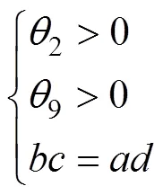
联立(9)、(10)、(16)与(17)可得到方程组(16)的解:

2.2 求解θ6和θ7


(0)根据图1得到:

根据引入的中间点可以将上述子问题2分解为2个子问题1:

由此解得关节变量6和7的值:


2.3 求解θ8
8通过构造子问题1求解,选取不在8上的点1,从图1中可以得到关系:

1在参考位形中的位置矢量为


求解可得8:

16=cos(1+6),16=sin(1+6)
3 期望位姿获取及可行解分析
3.1 目标姿态与末端执行器姿态映射建立
林果采摘机械臂用于采摘油茶果,考虑到油茶果花果同期的特点,只要合理控制振动机构的振幅和频率,振动式采摘相对齿梳式、剪切式等采摘方法有较高采摘效率与较低落花率[24],因此采摘机械臂工作方式为:通过末端执行器夹持油茶果树干,依靠末端执行器上的偏心机构产生振动力实现采摘。根据其工作方式,所求逆运动学解应使末端执行器到达树干位置并与树干垂直。
如图1所示,设检测系统已经测量到树干上2标记点的位置:p1=(p1xp1yp1z)T,p2=(p2xp2yp2z)T。并认为2位于沿树干方向更高位置,树干在机械臂坐标系下的6×1普吕克(plücker)坐标可以表示为[25]

式中为树干的普吕克坐标,为树干上夹持点的位置矢量,为树干的方向余弦。
根据定义可计算出与:
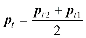
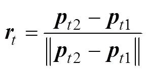
于是将检测装置所获取到的树干位姿信息转化为末端执行器期望位姿:首先,为使末端执行器到达树干所处位置,末端执行器应该满足:

其次,为使末端执行器能顺利夹持树干,末端执行器坐标系的轴应与树干方向余弦平行,轴与垂直,即:


满足式(29)的1有无穷多个,但考虑到机械臂碰撞体积及关节空间范围,如图1所示,结合路径最短原则[26],过机械臂坐标系原点引一直线与树干垂直于点,该直线的方向余弦即为满足上述条件且唯一的1。考虑到直线对原点的线矩不变,因此有:
可解得位置矢量:
于是:

此外,3与都是方向余弦向量,式(29)所给的平行约束使得3与的方向相同或者相反,再根据耗能最小原则,使末端执行器绕8转过的角度最小,因此有:

最后,根据右手坐标系建立规则,得到:

从而通过式(28)、(31)、(32)和(33)建立了物体位置坐标1和2与期望位姿1、2、3和之间的 映射。
3.2 可行解分析
式(21)及式(22)引起的多组解可能会导致计算出来的关节值不在关节空间范围内和求解缓慢的状况,甚至会致使机械臂腕部在工作中与树干碰撞,因此有必要根据表1所给关节变量取值范围对解的可行性进行讨论。仅从式(21)及式(22)无法直观地判断哪一组解满足要求,因此在腕关节位置处引入一局部坐标系O–XYZ,其原点位置与腕关节位置相同,其坐标轴方向与腕关节姿态矩阵所描述方向一致。根据相对运动不变性原理,末端执行器关于6和7的关节变量与所选参考系无关。末端执行器初始和最终位置在腕关节坐标系下的描述为
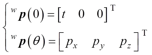
使用2.2节所述方法,得到与式(21)和(22)的等价解为


考虑到仅绕6和7转动,因此可认为始终在p为球心为半径的球面上,的各分量均小于,从而式(34)与(35)中的根式均有意义。再由表1所给关节变量7取值范围为–45°~45°,故相对应求解7的Atan2函数中第二个变量的值应该要大于0才能使求解的7始终在一、四象限内。所以式(35)所对应的式(22)是受关节变量行程约束的可行解。
4 试验与结果分析
4.1 试验设计及误差测量
如图2所示,以6自由度林果采摘机械臂、激光追踪仪及夹持目标搭建运动学试验平台[23],通过运动学试验验证所建立目标坐标与关节变量映射的正确性及所求的精确性。图2a右侧激光追踪仪坐标系原点相对机械臂坐标系原点的位置坐标为(-500 1 500 0)T,并设此为参考位形。激光追踪仪型号为FARO SI型,测量精度为10m。夹持目标为一根木条,木条上有2处标记点,两点相距580 mm。
整个试验分为2个阶段,第一阶段测试算法的可行性,第二阶段测试算法的精确性。在第一阶段,于机械臂工作空间内放置一夹持目标,其姿态随机。测量得到2标记点位置后,先通过式(28)、(31)、(32)和(33)获得机械臂的期望位姿,再通过式(18)、(22)和(24)计算关节变量值。将关节变量值输入至系统后,若机械臂能够到达夹持目标位置,则说明算法可行。
在第二阶段,因为机械臂有移动和转动2种关节,为使测量结果单位统一,所以通过比较末端执行器的位姿来评价结果;又由于求解机械臂运动学逆解需要用到姿态信息,而测量角度会引入较大误差[27-28],因此改为测量腕关节及末端执行器两端指关节1和2的坐标来间接获得末端执行器姿态。根据图1,可以得到测量点与机械臂位姿的关系:


然后通过以下步骤进行误差测量试验:
1)随机选取整数关节变量值并输入至样机之中。
2)测量2指关节及腕关节位置1、2与并由式(36)与(37)计算得到和=(1,2,3 )。
3)根据测量数据求解关节变量并将其输入至样机之中,重复步骤2)得到新的位姿与。
4)计算误差值并重复试验10次以评价算法的精确性,位置误差为
e=|–| (38)
再根据文献[29]所提方法先计算旋转误差矩阵,再化为四元数计算姿态误差:

将其转化为四元数得到[20]:

式中是对应的四元数,|为所求姿态误差。
4.2 结果与分析
4.2.1 可行性试验与分析
进行第一阶段试验,通过激光追踪仪获得标记点的位置(mm):

根据4.1节所述方法,计算得到末端执行器期望位姿为

再求得关节变量解为:
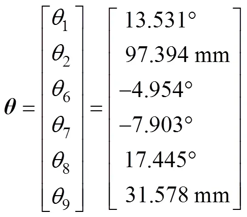
将关节变量值输入至样机中,结果如图2b与图2c所示,末端执行器到达目标所在位置且其夹持器已呈现利于夹紧目标的姿态,从而验证物体坐标到机械臂关节变量映射关系的可行性。
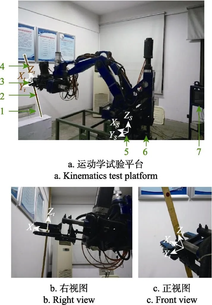
1. 夹持目标 2. 标记点Pt1 3. 末端执行器坐标系 4. 标记点Pt2 5. 基础坐标系 6. 林果采摘机械臂 7. 激光追踪仪
4.2.2 精度试验与分析
进行第二阶段试验,由式(38)与式(39)计算误差值,将位置误差各分量绘制为折线图,如图3所示。
从图3可知,末端执行器最大位置误差为6.597 mm,小于其夹持器200 mm夹持范围的3.30%,从而验证算法精度能够满足作业要求。此外,图3中3个轴的误差分量分散范围较小,而误差曲线整体偏移零线的程度较大,表明系统中可能存较大的常值性系统误差[30-31],机械臂的重复定位精度较低。
姿态误差试验结果如表3所示。由表3可知,本文所提方法得到的姿态误差较小,最大姿态误差不超过1°,满足林果采摘作业精度要求。

图3 末端执行器位置误差

表3 末端执行器姿态误差
5 结 论
针对Paden-Kahan子问题求解林果采摘机械臂逆运动学时需获取关节交点坐标的问题,本文结合矢量代数改进了传统子问题,提出了一种林果采摘机械臂逆运动学分析方法。该方法首先根据机械臂几何特征利用封闭结构方程获得主被动关节映射,将混联结构等效为串联结构;然后通过矢量代数获得关节轴交点坐标并结合Paden-Kahan子问题求解林果采摘机械臂运动学方程;再根据关节空间范围分析解的分布规律得到其可行封闭解;最后依据路径最短原则利用普吕克坐标将工作目标姿态映射为末端执行器期望位姿,得到目标位姿与关节空间完整映射。
1)所提方法基于旋量理论,能有效避免D-H参数法引入局部坐标系带来的奇异性;依据油茶果采摘机械臂作业方式及路径最短原则能直接获得可行解从而提高求解速度,所得封闭解形式能保证其数值稳定性;本质属于几何方法,所以不受具体结构限制并适用其它形状的工作目标。
2)试验结果表明所得解能使机械臂到达指定位姿,由解驱动的位置误差不超过夹持器最大开度的3.30%,最大姿态误差不超过1°,满足林果采摘要求。但试验所得各轴误差分量的分布范围与其相对零线偏差较大,表明系统可能存在较大的常值系统误差,课题组后续拟定开展机械臂误差分析与校正工作。
[1] Singh A, Singla A. Kinematic modeling of robotic manipulators[J]. Proceedings of the National Academy of Sciences India Section A: Physical Sciences, 2016, 87(3): 303-319.
[2] An H S, Lee J H, Lee C, et al. Geometrical kinematic solution of serial spatial manipulators using screw theory[J]. Mechanism and Machine Theory, 2017, 116: 404-418.
[3] Pena C A, Guzman M A, Cardenas P F. Inverse kinematics of a 6 DOF industrial robot manipulator based on bio-inspired multi-objective optimization techniques[C]//2016 IEEE Colombian Conference on Robotics and Automation (CCRA). IEEE, 2016.
[4] Xu J, Liu Z, Cheng Q, et al. Models for three new screw-based IK sub-problems using geometric descriptions and their applications[J]. Applied Mathematical Modelling, 2018, 67: 399-412.
[5] Man C, Xun F, Li C R, et al. Kinematics analysis based on screw theory of a humanoid robot[J]. Journal of China University of Mining and Technology, 2007, 17(1): 49-52.
[6] 孙恒辉,赵爱武,李达,等. 基于新旋量子问题改进一类6R串联机器人逆解算法[J]. 机械工程学报,2016,52(1):79-86. Sun Henghui, Zhao Aiwu, Li Da, et al. Improvement of the algorithm of the inverse kinematics calculation for 6R series robots based on one novel Paden-Kahan sub-problem[J]. Chinese Journal of Mechanical Engineering, 2016, 52(1): 79-86. (in Chinese with English abstract)
[7] Wang H, Lu X, Sheng C, et al. General frame for arbitrary 3R subproblems based on the POE model[J]. Robotics and Autonomous Systems, 2018, 105:138-145.
[8] Dong Y, Phan H N, Rahmani A. Modeling and kinematics study of hand[J]. International Journal of Computer Science and Applications, 2015, 12(1): 66-79.
[9] 赵杰,刘玉斌,蔡鹤皋. 一种运动旋量逆解子问题的求解及其应用[J]. 机器人,2005,27(2):163-167. Zhao Jie, Liu Yubin, Cai Hegao. Solution for one type of inverse kinematics sub-problems in screw theory and its application[J]. Robot, 2005, 27(2): 163-167. (in Chinese with English abstract)
[10] Murray R M, Li Z, Sastry S S. A Mathematical Introduction to Robotic Manipulation[M]. Florida: CRC Press, 1994:19-81.
[11] 钱东海,王新峰,赵伟,等. 基于旋量理论和Paden-Kahan子问题的6自由度机器人逆解算法[J]. 机械工程学报,2009,45(9):72-76. Qian Donghai, Wang Xinfeng, Zhao Wei, et al. Algorithm for the inverse kinematics calculation of 6-DOF robots Based on Screw throry and Paden-Kahan sub-problems[J]. Chinese Journal of Mechanical Engineering, 2009, 45(9): 72-76. (in Chinese with English abstract)
[12] 吕世增,张大卫,刘海年. 基于吴方法的6R机器人逆运动学旋量方程求解[J]. 机械工程学报,2010,46(17):35-41. Lü Shizeng, Zhang Dawei, Liu Hainian. Solution of screw equation for inverse kinematics of 6R robot based on Wu’s method[J]. Chinese Journal of Mechanical Engineering, 2010, 46(17): 35-41. (in Chinese with English abstract)
[13] 李盛前,谢小鹏. 基于旋量理论和Sylvester结式法的6自由度机器人逆运动学求解分析[J]. 农业工程学报,2015,31(20):48-54. Li Shengqian, Xie Xiaopeng. Anlysis of inverse kinematic solution for 6R robot based on screw theory and Sylvester resultant[J]. Transactions of the Chinese Society of Agricultural Engineering (Transactions of the CSAE), 2015, 31(20): 48-54. (in Chinese with English abstract)
[14] Sariyildiz E, Temeltas H. Solution of inverse kinematic problem for serial robot using quaterninons[C]//Proceedings of the IEEE International Conference on Mechatronics and Automation. Changchun: IEEE, 2009: 26-31.
[15] Gao Y, Chen W, Lu Z. Kinematics analysis and experiment of a cockroach-like robot[J]. Journal of Shanghai Jiaotong University(Science), 2011, 16(1): 71-77.
[16] 陈庆诚,朱世强,王宣银,等. 基于旋量理论的串联机器人逆解子问题求解算法[J]. 浙江大学学报:工学版,2014,48(1):8-14. Chen Qingcheng, Zhu Shiqiang, Wang Xuanyin, et al. Inverse kinematics sub-problem solution algorithm for serial robot based on screw theory[J]. Journal of Zhejiang University: Engineering Science, 2014, 48(1): 8-14. (in Chinese with English abstract)
[17] Wang H, Lu X, Zhang Z, et al. A novel second subproblem for two arbitrary axes of robots[J]. International Journal of Advanced Robotic Systems, 2018, 15(2): 1-7.
[18] Rocha C R, Tonetto C P, Dias A. A comparison between the Denavit–Hartenberg and the screw-based methods used in kinematic modeling of robot manipulators[J]. Robotics & Computer Integrated Manufacturing, 2011, 27(4): 723-728.
[19] Li Y, Zhu S, Wang Z, et al. The kinematics analysis of a novel self-reconfigurable modular robot based on screw theory[J]. DEStech Transactions on Engineering and Technology Research, 2016: 23-30.
[20] Dai J S. Screw algebra and kinematic approaches for mechanisms and robotics[M]. London: Springer, 2014: 49-80.
[21] Kevin M L, Frank C P. Modern robotics mechanics, planning, and control[M]. Cambridge: Cambridge University Press, 2017: 59-114.
[22] Gallardo-Alvarado J. Kinematic analysis of parallel manipulators by algebraic screw theory[M]. Switzerland: Springer International Publishing, 2016: 31-63.
[23] 阳涵疆,李立君,高自成. 基于旋量理论的混联采摘机器人正运动学分析与试验[J]. 农业工程学报,2016,32(9):53-59. Yang Hanjiang, Li Lijun, Gao Zicheng. Forward kinematics analysis and experiment of hybrid harvesting robot based on screw theory[J]. Transactions of the Chinese Society of Agricultural Engineering (Transactions of the CSAE), 2016, 32(9): 53-59. (in Chinese with English abstract)
[24] 王朋辉,李立君,高自成,等. 摆动式林果采摘头设计与分析[J]. 西北林学院学报,2015,30(5):288-291. Wang Penghui, Li Lijun, Gao Zicheng, et al. The design and analysis of oscillating fruit picking head[J]. Journal of Northwest Forestry University, 2015, 30(5): 288-291. (in Chinese with English abstract)
[25] 黄真,赵永生,赵铁石. 高等空间机构学[M]. 北京:高等教育出版社,2014:2-26.
[26] 李国利,姬长英,顾宝兴,等. 多末端苹果采摘机器人机械手运动学分析与试验[J]. 农业机械学报,2016,47(12):14-21. Li Guoli, Ji Changying, Gu Baoxing, et al. Kinematics analysis and experiment of apple harvesting robot manipulator with multiple end-effectors[J]. Transactions of the Chinese Society for Agricultural Machinery, 2016, 47(12): 14-21. (in Chinese with English abstract)
[27] 梅东棋. 六自由度工业机器人全姿态精度补偿方法[D]. 南京:南京航空航天大学,2015. Mei Dongqi. Compensation Method of 6R Industrial Robot positioning Accuracy[D]. Nanjing: Nanjing University of Aeronautics and Astronautics, 2015. (in Chinese with English abstract)
[28] Cho Y, Do H M, Cheong J. Screw based kinematic calibration method for robot manipulators with joint compliance using circular point analysis[J]. Robotics and Computer-Integrated Manufacturing, 2018, https://doi.org/ 10.1016/j.rcim.2018.08.001.
[29] Tabandeh S, Melek W W, Clark C M. An adaptive niching genetic algorithm approach for generating multiple solutions ofserial manipulator inverse kinematics with applications to modular robots[J]. Robotica, 2010, 28(4): 493-507.
[30] Liu Y, Wan M, Xing W J, et al. Generalized actual inverse kinematic model for compensating geometric errors in five-axis machine tools[J]. International Journal of Mechanical Sciences, 2018, 145: 299-317.
[31] 王先奎. 机械制造工艺学[M]. 北京:机械工业出版社,2013:199-226.
Inverse kinematics of 6-DOF hybrid manipulator for forest-fruit harvest based on screw theory
Li Lijun, Liu Tao, Gao Zicheng, Liao Kai, Li Yuzhuo, Xu Shibin
(410000,)
A method for inverse kinematics analysis based on screw theory was presented in this paper, which can directly map the position and orientation of the working object to the joint variables of the manipulator with its application to a full inverse kinematics analysis of forest-fruit harvesting manipulator characterized by a hybrid kinematic structure, 2P4R. The solution of inverse kinematics modeling derived by screw theory was commonly realized by Paden-Kahan sub-problem method, which decomposes a full kinematics problem into sub-problem with obviously geometrical meaning through choosing appropriate point, usually, intersection of adjacent joint, such as wrist joint, to reduce the number of the variable quantity, and then close-form solution can be easily obtained. However, in practice, it is hard to gain the position of those points through measure because of their absence before end-effector actually moving to the desired position. And few researchers mentioned this issue in the relevant literature. In order to discuss this problem, firstly, a geometrical method was proposed for this issue to obtain the position of the required point, wrist joint, according to the orientation of end-effector and its geometric properties and geometric relationships through using the vector algebra method. Furthermore, a mapping between driving and driven join was gained in order to simplify the solving process of the equation set at a later, according to the solution of the structural equation of the manipulator derived by the product-of-exponentials (POEs) formula and structural character of manipulator. Meanwhile, the closed-form solution for each driving joint variables was derived by employing the proposed method with Paden-Kahan sub-problem method. A mapping relationship between the plücker coordinates of the object and the location information of end-effector was derived through an algebraic method according to the principle of minimum displacement and its operating mode in which the gripper of end-effector should reach the position of the trunk with two labels detected by the robot vision system and be perpendicular to the orientation of the trunk. In addition, the problem of multiple solutions in the inverse kinematics analysis for the harvesting manipulator was solved according to the range of joint variables. Finally, the real-world experiment was performed under laboratory environment. In order to vertify the correctness and obtain the accuracy of the method proposed in this paper. A wooden stick with two markers was placed in the kinematics test platform as the object, which consisted of a laser tracker and a harvesting manipulator. Then, the values of each joint variable could be calculated via the proposed method according to the plücker coordinate data of the markers measured in the object. The results showed that the forest-fruit harvesting manipulator was driven by the solution of inverse kinematics to the position on the stick that its end-effect reached and normal to the stick, which meant this method could meet the requirements of the operating mode. Then ten sets of joint variable values were randomly generated where the positions were measured and the manipulator was sequentially driven by that. The joint variable values were calculated according to the positions through the method proposed in this paper. At last, the calculated results were re-inputted into the controller to drive the manipulator to the new positions. The two measure results on different positions driven by joint variable values generated and calculated were used to obtain the error. The results showed that the maximum position error of end-effector was 6.597 mm, far less than the open size of its gripper, 200 mm, and no more than 3.30%, with the maximum orientation error of 0.975°. The method in this paper was not limited by the specific structure, therefore it is versatile.
robots; harvesters; kinematics; screw theory; inverse kinematics; Paden-Kahan sub-problem; hybrid manipulator; forest-fruit harvest
2018-10-28
2019-02-12
湖南省科技重大专项(2017NK1010);国家自然科学基金(51475483)
李立君,湖南宁乡人,教授,博士生导师,主要从事智能林业技术装备的研究。Email:junlili1122@163.com
10.11975/j.issn.1002-6819.2019.08.009
TP242
A
1002-6819(2019)-08-0075-08
李立君,刘 涛,高自成,廖 凯,李禹卓,许世斌.基于旋量理论的六自由度林果采摘混联机械臂运动学逆解[J]. 农业工程学报,2019,35(8):75-82. doi:10.11975/j.issn.1002-6819.2019.08.009 http://www.tcsae.org
Li Lijun, Liu Tao, Gao Zicheng, Liao Kai, Li Yuzhuo, Xu Shibin.Inverse kinematics of 6-DOF hybrid manipulator for forest-fruit harvest based on screw theory[J]. Transactions of the Chinese Society of Agricultural Engineering (Transactions of the CSAE), 2019, 35(8): 75-82. (in Chinese with English abstract) doi:10.11975/j.issn.1002-6819.2019.08.009 http://www.tcsae.org
