Image-based app earance acquisition of ef fect coatings
2019-05-14JiFilipRadomavra
Jiˇr´ıFilip(),Rad om´ır V´avra
Abstract Paint manufacturers strive to introduce unique visual ef fects to coatings in order to visually communicate functional properties of products using value-added,customized design.However,these ef fects often feature complex,angularly dependent,spatiallyvarying behavior,thus representing a challenge in digital reproduction.In this paper we analyze several approaches to capturing spatially-varying appearances of ef fect coatings.We compare a baseline approach based on a bidirectional texturefunction(BTF)with four variants of half-dif ference parameterization.Through a psychophysical study,we determine minimal sampling along individual dimensions of this parameterization.We conclude that,compared to BTF,bivariate representations better preserve visual f idelity of ef fect coatings,better characterizing near-specular behavior and signif icantly therestricting number of imageswhich must be captured.
Keywords ef fect coatings;measurement;bidirectional texturefunction(BTF);appearance;psychophysical experiment
1 Introduction
Nowadays,digital appearances of materials play an important role in computer graphics and related industrial f ields like gaming and the f ilm industry.They are also crucial to many industrial sectors dealing with virtual product design and prototyping,as virtually designed products are often used for marketing even prior to the commencement of production. Therefore,the realism of material visualization and speed of the entire virtual product development cycle are major factors determining success in a market.Methods visualizing digital material appearance rely either on a mathematical model of materials or on captured data.In both cases,one requires measurementsto identify the main features of material appearance;the amount of data required is always driven by the material appearance representation used.
A four-dimensional bidirectional ref lectance distribution function (BRDF)[1]describes the distribution of energy ref lected to some specif ic viewing direction when illuminated from some other. Its extension,a six-dimensional spatiallyvarying BRDF(SVBRDF),additionally captures spatial dependency of ref lectance across a material surface. Whereas BRDF and SVBRDF impose restrictions on reciprocity,opacity,and a range of sample height variations,the six-dimensional bidirectional texture function(BTF)[2]generally does not meet these restrictions.This is due to non-local ef fects in rough material structure such as occlusions,masking,subsurface scattering,and inter-ref lections.Regardless of the representation used,the measurement process faces the problem of high dimensionality due to the sampling of many combinations of incoming and outgoing directions.This in practice results in the requirement for time-and resource-heavy capturing of thousands of bidirectional samples.The main motivation of this paper is to reduce the necessary number of captured images while still preserving high f idelity of a material’s visual features.Identif ication and minimization of the number of bidirectional samples required leads to an accelerated measurement process and consequently to the introduction of less complicated appearance capture devices,benef iting various industries.
Our analysis utilizes the half-dif ference parameterization[3];it can be applied to materials with nearlyf lat random structure represented by spatially-varying texture.A specif ic case of such material appearance is exhibited by ef fect coatings,e.g.,metallic or pearlescent paint,where the distribution of f lakes in a base coat causes globally isotropic appearance variations with local anisotropic high-frequency ref lectancechanges.It isoften referred to as“sparkle”,and is caused by randomly oriented,glittering particles.The structure of ef fect pigments is usually visible from several meters,so the visually correct representation of spatially-varying information is essential.
The main contributions of this paper are:
•analysis of several spatially-varying appearance representations stemming from half-dif ference parameterization;
•a perceptual experiment identifying minimal sampling along dimensions of this parameterization;
•validation of the minimal sampling sets on groundtruth data for static and dynamic rendering scenarios.
Our paper is structured as follows. Section 2 reviews prior work in ef fect coating appearance representation and capture.Section 3 discusses halfdif ference representation and its properties.Section 4 describes material samples and acquisition devices.Section 5 introduces the appearance representations tested while Section 6 compares their visual performance with respect to ground-truth data,and analyzestheir dynamic properties.Section 7 discusses method limitationsand Section 8 concludesthepaper.
2 Related work
This section overviews techniques related to material appearance data parameterization,capture,and modelling of ef fect coating appearance.
2.1 BRDF parameterizations
Instead of using a standard parameterization of incoming and outgoing directions based on spherical angles,Rusinkiewicz[3]introduced half-dif ference parameterization,which has better axis-alignment to typical variations in real materials.Romeiro et al.[4]suggested a method of BRDF dimensionality reduction in a half-dif ference parameterization giving a bivariate representation.An in depth analysis of BRDFs in half-dif ference parameterization was given by Burley et al.in Refs.[5]and[6],who introduced a characteristic slice,i.e.,aθh×θdsubset of BRDF space,and showed its convenience for analysis of physically related properties of the BRDFs in the MERL database.A parameterized non-linear sampling alongθhin the characteristic slice was applied in Ref.[7]for measurement of highly specular materials.Ward et al.[8]mentioned the possibility of using bilateral,quadrilateral,and radial symmetry to simplify the BSDF measurement process. While Helmholtz reciprocity and radial symmetry is widely used in many analytical BRDF models,its practical applicability to the spatial domain was not thoroughly studied due to the need for a goniometric acquisition device.Ferrero et al.[9]characterized the BRDF of special ef fect coatings using a half-dif ference parameterization of individual f lakes,wherehalf and dif ferenceelevation anglesθh,θdare denoted by f lake disorientation angleθflakeand f lake-related illumination angleθincrespectively.The same parameterization was applied in Ref.[10]for predicting the global appearances of ef fect-pigmented surfaces.Several methods exist for sparse acquisition of anisotropic BRDFs,either using minimal sampling in combination with a precomputed linear basis[11],or adaptive sampling along 1D slices in BRDF space[12].
2.2 Acquisition of spatially-varying reflectance
As ef fect coatings generally satisfy the assumptions of reciprocity and isotropy,a spatially-varying BRDF(SVBRDF)can be considered to be a suitable representation for such materials.Recently,several approaches for fast acquisition of SVBRDF have appeared.Dong et al.[13]estimated local anisotropic behavior using sparse sampling by near-f ield ref lectometry and completed appearance reconstruction by assignment of these measured BRDF clusters to non-measured per-pixel locations.Aittala et al.[14]introduced a system of SVBRDF capture without moving parts,allowing two-shot acquisition by means of a specif ic illumination pattern and processing in the frequency domain.Aittala et al.[15]proposed an approach to single-shot SVBRDF acquisition relying on a texture descriptor based on a deep convolutional neural network.Although these advanced approaches perform well for a variety of real-world materials,their ability to correctly capture specular peaks and sparkling features of ef fect coatings is unknown.To this end,capable procedural approaches for the realistic rendering of glossy sparkling materialsbased on micro-facet theory exist[16];however,a side-by-side comparison of their results to photographs of real materials has not been presented.Den Brok et al.[17]demonstrated the possibility of accurate BTF reconstruction from sparse multiplexed measurements.Spatially localized anisotropic ef fects of fabrics were f itted from BTF data in Ref.[18].
2.3 Acquisition and modelling of effect coatings
One of the f irst attempts to model ef fect coatings by means of the BRDF model was by G¨unther et al.[19],where the spatial sparkling ef fect was introduced using either physical[20]or statistical[21,22]models of sparkling f lake sizes and orientations. Later,Mihalik and Durikovic[23]introduced a method of separately capturing and f itting BRDF data and spatially-varying sparkle ef fects. More advanced techniques extend to spatially-varying appearance representation using a BTF.Rump et al. [24]collected dense BRDF measurements from relatively large samples and f itted the Cook–Torrance model to measured BRDF data.The residual sparkling appearance was represented using BTF images compressed for individual viewing directions using PCA.During the visualization stage,the BRDF value was combined with a randomly sampled BTF patch.In follow up work,Rump et al. [25]considered detailed angular analysis of f lake properties from video. The information obtained was used to guide sampling and example-based compression of the paint’s measured BTF.Compression is based on histogram clustering and achieves signif icantly higher compression rates than previous approaches.An extended statistical representation for realtime rendering of ef fect coatings was presented in Refs.[26,27]. Kautz et al. [28]and Xu et al.[29]extended BTF by editing operations,allowing modif ication of its local geometrical and ref lectance properties.Alternatively,anisotropic ef fects can be also introduced using statistical models.Yan et al.[30]presented a parametric model of anisotropic glints based on local normal distribution functions.An approach to scalable modelling of anisotropic ef fects using anisotropic spherical Gaussians was proposed in Ref.[31].
2.4 Psychovisual analysis of material ap p earance
Psychovisual analysis of material appearance aims to provide intuitive navigation BRDFs in parametric space[32–34].Further work considered perceptually driven compression [35]and f iltering [36]of bidirectional texture functions.We are unaware of any psychophysical analysis of low-dimensional ef fect coating representations operating in a spatio-angular domain.
BRDF measurement and modelling methods disregard important spatial information.While BTFbased methods allow photorealistic visualization,they fall short due to their high demands during acquisition,compression,and visualization stages.Flake physical and empirical modelling approaches do not require extensive input data,but often suf fer from limited descriptiveness of the model and inaccurate parameter f itting. Although the SVBRDF might seem as a good representation for ef fect coatings it has several disadvantages.Pigments exhibiting anisotropic ef fects have highly specular locally anisotropic behavior,and per-pixel appearance is often result of light interaction with multiple pigment f lakes and coating layers rather than pure mirror-like ref lection from a uniformly oriented f lake.In contrast to the reviewed approaches,our method does not rely on any form of data f itting or support of BRDF models.Further,it requires capture of a lower number of images than BTF while allowing for a correct representation of near specular behavior.
3 App earance parameterization
The BRDF is a four-dimensional function fr(θi,θv,ϕi,ϕv)of the illumination directionωi={θi,ϕi}and viewing directiondef ining how light is ref lected at the surface of a material;θ∈is the elevation angle andϕ∈[0,2π),the azimuthal angle of a spherical coordinate system.This representation can be directly further extended into the spatial domain by means of the SVBRDF or BTF,as fr(x,y,θi,θv,ϕi,ϕv).
A general four-dimensional function can describe anisotropic materials,i.e.,those with variable ref lectance when rotated about a surface normal.This property is common for many real-world materials,due to directional elements such as thread in fabric or grain in wood.A three-dimensional simplif ication of a BRDF is called an isotropic BRDF fr(θi,θv,∆ϕ= ϕv−ϕi),and it neglects anisotropic appearance. A main limitation of standard parameterization using spherical angles is its inef ficient representation of important features,such as specular highlights,not aligned with axes of the coordinate system.Therefore,locations of highlights depend on several variables which limit practical usage of the standard parameterization(such as BRDF compression). These limitations can be overcome by means of a half-dif ference(HD)parameterization proposed by Rusinkiewicz[3].He suggested a change of variables from fr(θi,ϕi,θv,ϕv)to fr(θh,ϕh,θd,ϕd)as shown in Fig.1.The BRDF is represented by the half vector H={θh,ϕh}between the illumination and viewing directions,and by the dif ference vector D={θd,ϕd},which represents the illumination direction I with respect to the half vector H.
The half-vector parameterization is,due to its ef fective description of specular highlights,often used as a core of analytical BRDF models,e.g.,Refs.[37,38]. The shape of specular highlights is represented by the elevation angle of the half vectorθh,and the specular ref lection is obtained forθh=0◦.A non-linear sampling alongθhis often used to reproduce a highly specular material,allowing use of a lower number of samples[32].Anisotropic behavior is controlled by the azimuthal angle of the half vectorϕh,representing rotation of a sample around its normal. Reciprocity is introduced by symmetry of the azimuthal angle of the dif ference vectorϕd=ϕd+π.Therefore,angles range as:.Isotropic BRDFs can be described by the three-dimensional variant fr(θh,θd,ϕd).
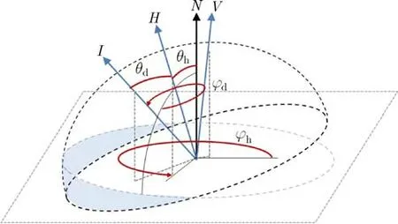
Fig.1 A half-dif ference parameterization of incoming I and outgoing V directions.
Marschner[39]suggested how to reduce captured data by means of bilateral symmetry and an extension to the concept of isotropy.Rusinkiewicz[3]def ined BRDF reciprocity in half-dif ference parameterization as folding data along angleϕd=ϕd+π.Romeiro et al.[4]studied half-dif ference parameterization and concluded that reciprocity and bilateral symmetry impose periodicity for incoming and outgoing directions about a half-way vector:They further def ined bivariate BRDFs as constant functions ofϕd,understanding their properties as a direct generalization of isotropy,bilateral symmetry,and reciprocity.
A simple experiment on the UTIA BRDF database shown in Fig.2 demonstrates that bivariate representation using constantϕdat 90◦provides the lowest BRDF reconstruction error.This is due to the fact that forϕd=90◦,the majority of the ef fective part of the hemisphere around half-direction H is above the plane def ined by the material surface(see Fig.1).Figure 2 also demonstrates symmetry around ϕd=90◦,suggesting that the majority of BRDFs are bilaterally symmetric[4].Finally,our analysis revealed that using f ixedϕd=90◦introduced only a relatively low reconstruction error:45–58 dB for PU PSNR[40].
4 Material specimens and data acquisition
4.1 M aterial sp ecimens
Ef fect pigments can be,based on the principle of chroma and sparkling ef fect generation,roughly divided into three categories that in practice are often combined in coating systems[41]:(1)metallic pigments,relying mainly on geometrical properties of pigment f lakes and their ref lectance,(2)interference pigments,in which color ef fects are caused by light wave interference with a transparent substrate coated with materials of high refractive indices,and(3)dif fractive pigments,decomposing light at a dif fraction grating of a frequency close to the wavelength of the incoming light.We measured four kinds of coatings featuring state-of-the-art ef fect pigments in their base coat layers(see Fig.3),introducing specific spatial behavior that plays a key role in the enhancement of material visual attractiveness:
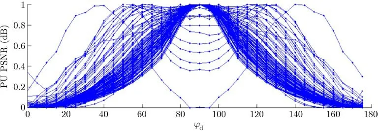
Fig.2 Normalized BRDF reconstruction error PU PSNR[40](normalized to[0,1])as a function of constantϕd used for data reduction.
VMP(Decomet):a mirror-like,highly-reflectivecoating(category 1)based on well-aligned and oriented vacuum metallized pigments(VMPs)with mean particle size 12µm,Silverdollar(AluMotion):an automotive coating including aluminum f lakes of silverdollar morphology(category 1)with mean particle size 18µm,UTP(Zenexo):a high-sparkle contrast,pearlescent coating including an ultra-thin,colored aluminium pigment(UTP)with a mean particle size 21µm(category 1),and Polychromatic(MultiFlect):a polychromatic coating(category 3)including a holographic ef fect pigment with a mean particle size 150µm.All but Decomet feature high sparkle contrast due to angularly dependent pigment ref lectivity,and are highly-specular due to a clear coat used on top of the ef fect pigmented base coat layer.The polychromatic pigment also exhibits a unique,gonioapparent chromaticity due to a regular grating of pigment f lakes introduced by means of optical lithography.Due to its specif ic appearance,this material represents a challenge to the both capture and visualization processes.
4.2 App earance acquisition
Weused a four-axisgonioref lectometer[42]to capture the angularly dependent appearances of coatings.The size of the captured sample was 6cm×6cm,camera distance was 2m,and light distance was1.5m.The spatial resolution of the images was 350 DPI.The device was geometrically and colorimetrically calibrated,and the measured f lat sample normal was accurately aligned within the coordinate system of the device.
For all tested representations,a set of material surface images was taken with varying lighting and viewing directions,and small tiles of approximately 120×120 pixels,corresponding to 5mm×5mm,were cut[43]. Raw tiled image data were stored in uncompressed binary format and directly accessed using lookup functions in our OpenGL rendering application.Linear interpolation was used for values for non-measured directions:for BTF representation,this was barycentric interpolation using the 3 closest directions,while for half-dif ference parameterization we used linear interpolation from the two closest directions in each dimension.
4.3 Pigment angular behavior
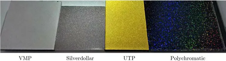
Fig.3 Four dif ferent ef fect pigments used in the base coats of ef fect coatings used in our experiments.
We analyzed typical dynamic behavior and the angular lifetime of individual ef fect pigments.We f ixed a camera at 45◦and captured the entire in-plane geometry of illumination elevations with sampling step 1◦.Analysis of individual pixels revealed that the angular pixel lifetime was between 5◦and 10◦.We selected a representative pixel with the highest contrast as shown in Fig.4.One can observe dif ferent behavior for dif ferent ef fect coatings.For a polychromatic coating with large f lakes,we obtained wider and smoother peaks than for UTP and silverdollar with f ine f lakes.For f ine f lakes,the scattering over the peak can becaused by thecontributionsof several f lakes to the same pixel location.Additionally,we show a non-linear sampling inθhfor steps 5◦(red circles),validating that this density should suf fice to reasonably characterize typical pixel dynamics.
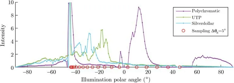
Fig.4 Typical behavior of a high-contrast pixel for the tested coatings,for in-plane geometry with the camera at 45◦and moving light.
5 Capturing spatially-varying app earances of ef fect coatings
This section introduces variant representations of individually tested ef fect coating appearance,and compares renderings using them.
5.1 Uniform sampling using BTF
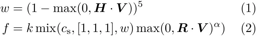
First,we captured the spatially-varying appearance of tested materials by means of a BTF[2]using 81 illumination and viewing directions distributed uniformly over a hemisphere[44].This produced 6561 HDR images of the material surface.Measurement using a gonioref lectometer took approximately 20 hours;the resulting appearance of the captured BTF is shown in Fig.8(a).As the BTF angular sampling is uniform,the shape of the specular highlight is not sampled properly,and intensity captured for ideal specular ref lection leaks out to neighboring directions due to angular interpolation.To avoid these issues,we replaced values in specular ref lections by the closest valuescaptured nearby.In addition,we used a Phong model modulated by Schlick’s approximation of Fresnel ref lection to represent the highlights more properly where mix(.)is a linear blending function,csis specular RGB color,k is an attenuation parameter,andαis a shininess parameter.H,V,R are half vector,viewing vector,and ideal mirror direction.
Although we f it intensity and RGB color to the discarded specular ref lection data,the model is,due to lack of data,unable to correctly f it the unknown width of the specular highlight as well as the characteristic near-specular behavior of f lakes.Moreover,physical parameters of the measured materials,e.g.,refractive indices,are unavailable.Therefore,we f it the parameters manually to obtain the best perceptual results.Results are shown in the second row of Fig.8(b).Although Fresnel ref lection can improve the appearance of specular highlights in a BTF considerably,unless additional samples are taken near specular highlights,performance of automatic f itting is limited.Note that this process was not applied to the half-dif ference representationbased sampling approaches presented in the paper.
5.2 Sampling in half-dif ference parameterization
This section proposes several data reduction variants of half-dif ference parameterization. We use this representation as it allows for the capture of near specular ref lections in more detail,while reducing the number of angular samples needed.If one were to use a sampling step of 5◦in all dimensions while using a standard square root non-linear sampling along elevation of half-vectorθh,and to rely on the reciprocity assumption,one would need to capture nθh×nθd×nϕh×nϕd/2=18×18×72×72/2=839808 images.Finally,one could apply bilateral symmetry by additional folding alongϕd=ϕd+π/2[4],arriving at 18×18×72×19=443232 images.As this number of images is still too high to be captured using the goniometer,we reduced them by resorting to assuming constant BRDF values along dimensions ϕdandϕh.We tested four options.
5.2.1 Isotropic representation:constantϕh(∆θh/
Our analysis of BRDFs of captured materials in a typical BTF angular sampling[44](see the f irst row of Fig.5)revealed that they do not globally exhibit any anisotropic behavior.
This was expected as the data microstructure is arbitrary,due to a random distribution of f lakes in the binder.In theory,the isotropic assumption works only for nearly f lat materials that do not exhibit non-local shading and masking ef fects.However,it also can be extended to special ef fect paints exhibiting globally isotropic appearance when these ef fects are present but considerably suppressed due to relatively thin layers of binder and upper coatings.Unfortunately,this representation neglects local anisotropic ef fects of individual f lakes and impacts its dynamics as discussed further. As local anisotropic behavior is neglected,the same values are replicated for all azimuthal directions of sample orientation.Applying isotropy,reciprocity,and bilateral symmetry assumptions reduces the number of imagesneeded to 18×18×19=6156 images.However,some of the combinations are invalid as they position incoming or outgoing directions below the upper hemisphere,resulting in only 4951 valid samples. Further,since our goniometer has a technically limited range of incoming and outgoing grazing angles,we restricted the maximal elevations to 75◦.This further reduces the number of captured images to 3485 unique bidirectional samples.When we visualize appearance using such captured isotropic representations,we obtain results as shown in Fig.8(c).We observe a considerable improvement in the capturing of specular highlights while still preserving important visual features.
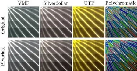
Fig.5 BRDFs captured using hemispherically uniform sampling of 81 viewing(horizontal axis)and illumination(vertical axis)directions(total 6561 samples)[44]compared to BRDFs interpolated from the captured bivariate isotropic representation(∆θh/∆θd=5◦/15◦).
5.2.2 Bivariate isotropic representation:constant

One can restrict the number of samples further by assuming radial symmetry in the material structure.This holds globally due to the random distribution of f lakesand disregardstheef fectsof mutual viewing and light rotations around the half-vector.Then we can extend the concept of bivariate BRDF[4]to bivariate SVBRDF and capture only images belonging to the characteristic slice depending onθhandθd[5]for f ixedϕd=90◦,which conveys most of the information.This restricts the number of images to nθh×nθd=18×18=324;again due to the technical restriction on maximum elevation,only 243 imagesare captured.Renderingsusing thissubset are shown in Fig.8(d)and are barely visibly dif ferent to the complete isotropic representation in the third row.
Reduced bivariate isotropic representation.
We captured the bivariate representation with a sampling step of 2◦along both dimensions.For incoming and outgoing elevations in[0◦,75◦],we collected a total of 1471 images.When the values across the images were averaged,we obtained characteristic BRDF slices as shown for three of the materials in Fig.6.Apart from a typical specular highlight presented by white stripes at the tops of the images,for the polychromatic sample we observe a rainbow light dif fraction ef fect of two subsequent dif fraction orders[45].We performed a psychophysical study analyzing maximal sampling steps in this representation(see Appendix)and we conclude that one can use 5◦sampling steps along θhand up to 15◦sampling steps alongθd,resulting
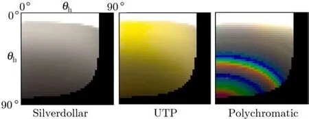
Fig.6 Characteristic BRDF slices obtained by averaging along spatial coordinates for tested materials.The vertical axis corresponds toθh,the horizontal axis toθd(1471 samples).
in just 83 samples.Distribution of samples in this minimal bivariate isotropic sampling is illustrated in Fig.7.
5.2.3 Anisotropic representation:constantϕd(∆θh/

One can extend bivariate representation to preserve local anisotropic ef fects(i.e.,dynamic f lake glittering)by acquiring the characteristic sliceθhandθdfor various azimuthsϕhof material rotations under a f ixed minimal measurement geometry specif ied by sampling alongθhandθd(see Fig.7).For azimuthal steps∆ϕh=15◦,83×nϕh=83×24=1992 imagesare taken.Comparison of renderings to those from other representationsin Fig.9(e)showssimilar performance for static scenes;however,this representation better captures dynamic behavior of f lakes,as discussed in Section 6.4.
5.2.4 Bivariate anisotropic representation:constant

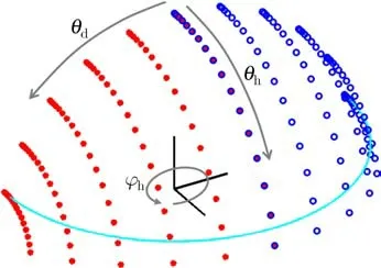
Fig.7 The minimal set of 108 bidirectional samples needed to capture ef fect coating appearance in half-dif ference parameterization for f ixed ϕd=90◦and angular steps∆θh/∆θd=5◦/15◦.The incoming(red)and outgoing(blue)directions span a quarter hemisphere and are symmetrical.The cyan line represents maximal elevation angles captured resulting in 83 samples.
Finally,we further limited the anisotropic representation by keeping bothϕdandθdconstant and thus acquiring only a data slice characterized by spherical angles def ining the half-vector,i.e.,θhandϕh.The sampling points alongθhcorrespond to cameras and lights in the same direction(simultaneously red and blue points in Fig.7).These sampling points are then replicated in dif ferent azimuthal angles specif ied byϕh.Note that sampling alongθhglobally characterizes the coatings appearance,while sampling along ϕhbrings anisotropic sparkling ef fects.For a half-vector elevation step∆θh=◦and azimuthal step∆ϕh=15◦,only 15×24=360 images are needed.As building such a coaxial setup might be impractical in many cases,we also tested positions of light and camera 15◦azimuthally apart. In fact,we obtained nearly identical results.A comparison of renderings to those from other representations in Fig.9(f)shows similar performance for static scenes;however,this representation is superior in dynamic scenariosasdiscussed in Section 6.4.It preservesboth dynamics of f lakes as well as accurate near-specular behavior,while compared to BTF representation,it requires only a fraction of the samples as well as a less complicated acquisition procedure with mutually f ixed lights and cameras rotating around the measured material.
6 Results
This section compares the results from the tested representations to photographs and ground-truth data using two independent experiments.Further,it also compares dynamic properties to a video of a real coated object.
6.1 Perceptual comparison of tested methods
In this psychophysical experiment we compared subjects’impressions from a rendering of static scenes using the tested representations. A total of 106 subjects responded as to whether they could observe dif ferences between rendered images.The study was web-based,i.e.,run in an uncontrolled environment using various screens,although subjects were advised to run it in a dim room environment. Finally,from yes/no(1/0)responses across all subjects,a mean opinion score was computed.We compared visualizations of BTF+Fresnel vs.isotropic SVBRDF representation(the second and third rows of Fig.8)and of isotropic vs.isotropic bivariate SVBRDF representations(the third and fourth rows of Fig.8).The mean opinion scores in Fig.10 show that the majority of subjects were able to clearly dif ferentiate(91%of subjects)between images captured as a BTF and those captured as an isotropic SVBRDF as shown in the graph on the left,while many fewer(34%of subjects)were able to dif ferentiate between isotropic and isotropic bivariate SVBRDFs as shown in the graph on the right.Note that for both representations a step of 5◦was used along all dimensions.We assume that the dif ferences between the BTF and isotropic SVBRDF were biased by dif ferent shapes of specular highlight due to its modelling for BTF data by the Fresnel model.Another possible bias could be caused by subjects focusing on local f lakes rather than on global visual similarity;we advise the reader to assess the methods in the video in the Electronic Supplementary Material(ESM)for themselves.
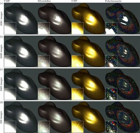
Fig.8 Rendering of captured spatially-varying appearance using dif ferent representations:(a)raw BTF measurements,(b)BTF measurements with specular highlight represented by Fresnel ref lection,(c)isotropic measurements:constantϕh,(d)isotropic bivariate measurements:constantϕh andϕd.
6.2 Validation using photographs
Probably the most straightforward way of assessing captured appearance quality is by comparing it to real appearance.To this end,we coated objects with two ef fect pigments:VMP and Polychromatic.Moreover,Polychromatic was used both with and without a clear coat(CC).We took a photograph of the coated objects inside the acquisition setup and then compared it with renderings from several appearance representations. To achieve this,we captured the 3D geometry of the object and adjusted viewing and lighting conditions so as to render its appearance similar to that in the photograph.Our results for Polychromatic with clear coat are shown in Fig.9(more results are shown in the ESM).BTF enhanced by Fresnel ref lection shows an unnaturally clear specular highlight without nearspecular sparkling.The representations based on the half-dif ference parameterization perform considerably better.Moreover,their results can be further improved by using parametric non-linear sampling alongθhas suggested in Ref.[7].The elongated shape of the specular highlight in our renderings,when compared to the circular one in the photograph,is likely due to use of an ideal rather than real point light source with a non-zero area.We can eliminate possible impact of our visualization pipeline as these these elongated highlights caused by object geometry also appear in theper-pixel ground truth measurements in Fig.11(a).An additional psychophysical evaluation of photographsand rendered images,shown in the ESM,concludesthat,whiletheir performanceof isotropic and bivariate representations is comparable,they perform significantly better than BTF-based approaches.This supports our conclusion that bivariate representation is a promising approach for the effective capture of the appearance of effect coatings in static rendering scenarios.
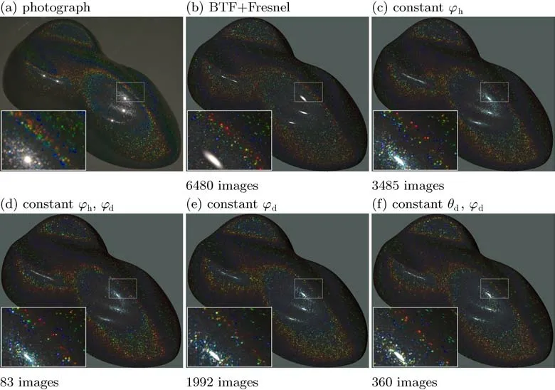
Fig.9 Comparison between captured spatially-varying representations and photographs:(a)photographs of the coated object,(b)uniform BTF measurements with the specular highlight represented by Fresnel ref lection,(c)isotropic representation using step a of 5◦,(d)bivariate isotropic representation using 83 images(∆θh/∆θd=5◦/15◦),(e)anisotropic representation(∆θh/∆θd/∆ϕh=5◦/15◦/15◦),(f)bivariate anisotropic representation(∆θh/∆ϕh=5◦/15◦).
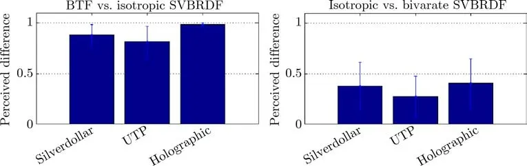
Fig.10 Perceived dif ferences between uniform BTF and isotropic SVBRDF measurements(left),and isotropic and bivariate isotropic SVBRDFs(right),both with step 5◦.
6.3 Validation using ground-truth
In the second validation experiment,we selected a small area of 100×50 pixels around a specular highlight in a rendered image,as shown in the f irst row of Fig.11.For each of these rasterized pixels,the underlying 3D model geometry was evaluated and illumination and viewing directions restored;then,exactly thesedirectionswereused for thebidirectional measurement of materials.In this way,we obtained a ground-truth data image of resolution 100×50 pixels as shown in Fig.11(a)(intensity of the VMP material is reduced by a factor of 10 for better visibility).This data was used for a direct pixel-wise comparison with each tested appearance representation:(b)a raw BTF,(c)a BTF with Fresnel model for specular highlights,(d)isotropic measurements,(e,f)bivariate isotropic measurements for f ixedϕd=90◦and angular steps in∆θh/∆θd= 2◦/2◦and 5◦/15◦,respectively.Note that in this particular case,the parameters of the Fresnel model were manually tuned to provide results as close as possible to the groundtruth data,but one can still spot a considerable dif ference from the original.On the other hand,the appearances from isotropic and bivariate isotropic representations show a very close resemblance to the ground-truth data.
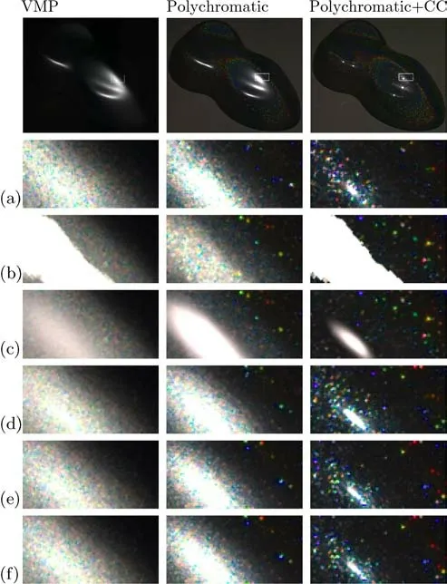
Fig.11 Comparison between captured spatially-varying representations and ground-truth measurements:(a)per-pixel ground-truth measurements,(b)raw BTF measurements,(c)BTF measurements with the specular highlight represented by the Fresnel ref lection,(d)isotropic measurements,(e,f)bivariate isotropic measurements for ϕd=90◦and steps∆θh/∆θd=2◦/2◦and 5◦/15◦respectively.
6.4 Analysis of dynamic behavior
This section compares dynamic properties of real ef fect coating appearance to renderings based on the tested variants of half-dif ference parameterizations.Weanalyzed this behavior in video of an object coated with polychromatic pigments alongside renderings of:a BTF+Fresnel model,isotropic measurements,minimal bivariate isotropic sampling for∆θh/∆θd=5◦/15◦,and anisotropic sampling using minimal bivariate sampling for dif ferent sample orientations with∆ϕh=15◦.To capture ground truth behavior of f lakes,we followed the analysisof typical angular f lake lifetimefrom Ref.[25]and varied both light and object positions in 0.5◦steps,taking 720 images for the full rotation of light/object.Videos showing the dynamic appearanceof tested representationscompared to real material are provided in the ESM.
We also compared dynamical behavior of the representations computationally by analyzing perpixel behavior at point positions across 720 frames.Figure 12 shows per-pixel variance for the tested methods;their mean values across an entire object area are shown in Fig.13.First,one can see that isotropic and bivariate isotropic representations show signif icantly fewer active f lakes and thus very low dynamics,due to replicating the same images for variousϕdand/orϕhangles.On the contrary,BTF with Fresnel ref lection modelling achievessignif icantly more excited f lakes and thus preserves dynamics much better but cannot preserve the surroundings of specular highlights correctly as shown in Fig.12.Finally,the anisotropic representation performs even slightly better than BTF as it captures azimuthal views for dif ferent sample orientations.
Although there are still some dif ferences in videos due to natural phenomena not captured in the renderings such as light ref lection from the table,we can conclude that while disregarding variation along ϕddoesnot havea signif icant impact on visual quality,capturing anisotropic behavior alongϕhis crucial for preserving local anisotropic behavior in dynamic scenes.In other words,disregarding ef fects of light and viewing direction rotationsaround a half-vector is signif icantly less visually apparent than disregarding ef fects of light and viewing direction rotations around a surfacenormal.This conclusion is also supported by the fact that the bivariate anisotropic representation has the best dynamic behavior as shown in Figs.12 and 13.
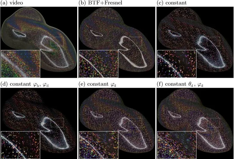
Fig.12 Comparison of original f lake dynamics to those from the tested representations.Colors represent per-pixel dif ferences computed across 720 frames varying point-light position over the object.
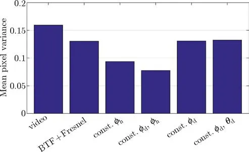
Fig.13 Comparison of real material dynamics to dynamics of the tested representation renderings using mean per-pixel variance across entire object in Fig.12,computed across 720 frames varying point-light position over the object.
7 Discussion
7.1 Recommendations on ef fect coating measurement
Our results suggest that only minimal bivariate isotropic sampling of a characteristic slice is needed for ef fect coating reproduction in static scenarios,while for dynamic ones,the best results can be achieved using a bivariate anisotropic slice,at the cost of slightly more samples.For bivariate isotropic representation one needs only to sample a quarter hemisphere over the material symmetrically along a plane orthogonal to that def ined by a surface normal and half-way vector as shown in Fig.7.This suggests the possibility of designing a measurement device with only a single mechanical degree of freedom consisting of an arc simultaneously holding lights and cameras rotating over the material surface around a horizontal axis. Non-linear uniform sampling alongθhcould be realized by using various nonuniform rotation steps of the arc,while sampling alongθdwould be determined by the number of lights and sensors and their distribution over the arc;only six are needed in the case of∆θd=15◦.As already mentioned,using a bivariate isotropic representation for capturing of ef fect pigments also imposes limitations on the dynamics of pigment f lake behavior. This can be resolved by using bivariate anisotropic representation,where one needs to uniformly sample only the half angle over the hemisphere.To capturebetter dynamicsof individual f lakes using this representation,another setup with one mechanical degree of freedom would suf fice.This could be achieved by using an arc outf itted with lights,and cameras would rotate around the normal of themeasured sample.Wehavefound that variation alongϕhrepresents most of the dynamic behaviour,so to capture dynamic behavior more accurately,we must increase sampling density specif ically along this dimension.
7.2 Extension to other materials
Weconclude that whilebivariate representation works well for the reproduction of ef fect coatings in static scenes,for correct reproduction of their dynamic behavior,one should capture bivariate isotropic sampling for dif ferent material orientations.This approach neglecting only data alongϕdcan also be extended to other nearly f lat anisotropic materials such as fabric,wood,etc.Figure 14(left)shows an example of such an extension to highly anisotropic polyester fabric providing the same visual quality as BTF representation while requiring less than a third of of the data images.
7.3 Future work
The current form of our implementation does not consider light refraction at the interface between a clear coat and coating layer.An update of captured illumination directions taking into account refractive indices of layers might further optimize performance for clear-coated materials.Our methods were tested on four ef fect coatings only;however,we do not view this as a limitation since we purposely tested it on challenging dif fraction ef fect pigments,and assume that the conclusions drawn in this paper are valid for a majority of typical ef fect coatings.
The captured bivariate representations are publicly available for research purposes at ht t p://bt f.ut ia.cas.cz in the form of binary f iles with corresponding loading and look-up functions.
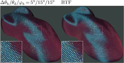
Fig.14 An extension of the bivariate isotropic representation to measurement of anisotropic materials by a sampling alongϕh represented by 1992 images(left),compared to a standard uniform BTF using 6561 images(right).
8 Conclusions
Thispaper analyzesapproaches to capturing spatiallyvarying appearances of ef fect coatings.We compare uniform sampling using a bidirectional texture function(BTF)with several sampling variantsrelying on assumptions of data constancy along dimensions of half-dif ference parameterization. In total we compared f ive dif ferent appearance representations on four ef fect coatings.Using several psychophysical experiments,we identif ied minimal sampling steps along individual dimensions of the half-dif ference parameterization.Further,we have shown that for static scenes,a bivariate isotropic representation providessatisfactory results,while for dynamic scenes,local anisotropic behavior of coating f lakes can be most ef fectively captured by bivariate anisotropic representation,completely neglecting light direction with regard to half-vector. Both representations requireconsiderably fewer captured imagesthan BTFbased approaches,while representing near-specular behavior more accurately.
Appendix:Perceptually optimized bivariate sampling
This section describes a perceptual experiment identifying appropriate sampling steps along the two dimensions of the characteristic slice(θh×θd).We captured the bivariate SVBRDFs with a sampling step of 2◦and analyzed perceived dif ferences as a function of the sampling step alongθhandθd.In this experiment we gradually downsampled the original angular resolution in both dimensions to identify the minimal resolution still preserving all visually relevant features of tested materials.We designed an experiment as a two-alternative forced choice(2AFC)decision task,i.e.,we prepared experimental stimuli consisting of two images and asking subjects to state whether they could observe dif ferences between the images.The subjects were advised to judge based on global appearance and not only on a localized comparison of individual pixels.The order of the two images presented was random,and the remaining space on the screen was set to dark gray.Note that although we did not use a ground truth in our experiment as it was not available,we did attempt to obtain information on visual distance between individual methods or their settings.
The study was web-based,i.e.,run in an uncontrolled environment on various screens,although subjects were advised to run it in a dim room environment.As Fig.6 demonstrates,most of the changes in data are alongθh(the vertical axis);the tested resolution steps were 2◦,4◦,6◦,8◦,and 10◦,while the variations alongθd(the horizontal axis)were signif icantly lower:the tested steps were 2◦,8◦,and 14◦.For each combination of valuesθhandθdwe rendered one image.In each test,we showed such an image side-by-side with a reference rendering using the shortest sampling step 2◦along both dimensions.This gave us 15 stimuli per set and 45 images in total.The orders of images in a pair,and also pairs in a session,were random.No resampling to rendered images was applied when images were produced.A total of 106 subjects participated in the experiment out of which 65 completed all trials.We recorded on average over 75 responses for each stimulus image.The average duration of stimulus observation was 5.1s and total time of the entire session was 4.1min.To evaluate the signif icance of the obtained data we used hypothesis testing.Due to the dichotomous nature of the data,we used a Cochran Q-test[46]for testing a null hypothesis that subject responses to a comparison of renderings with dif ferent sampling steps had the same number of positive and negative responses.We found that for all three test sessions,wecould reject thenull hypothesisat a 5%signif icance level with pval<10−14.
When we average yes/no(1/0)responses across all subjects,psychometric data are generated.The 3D plots in Fig.15 show psychometric data as a function of sampling density alongθhandθdfor three tested materials.
The data in each graph suggest that while subjects performed similarly for Silverdollar and UTP,they perceived higher dif ferences for Polychromatic.The higher visual dif ferences resulted from a disruption of the original holographic ef fect due to coarse sampling.Note that the guess rate was on average 0.2,i.e.20%of subjects reported a dif ference although the images were the same.An even more important f inding was that while subjects were sensitive to the increase in sampling step alongθh,their responses to step increase alongθdwere almost negligible.The psychometric data averaged alongθdwith corresponding variances across all subjects are shown in Fig.16.One can observe a signif icant drop of variance afterθh=4◦where the majority of subjects identif ied a dif ference.From the results we conclude that one can use 5◦sampling steps alongθhand up to 15◦sampling steps alongθd,resulting in 83 valid samples only.
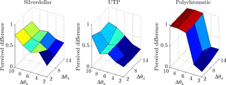
Fig.15 Psychometric data from the experiment showing perceived dif ference as a function of sampling steps alongθh,andθd for Silverdollar,UTP,and Polychromatic.
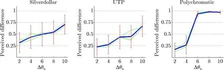
Fig.16 Psychometric data averaged alongθd from the experiment showing perceived dif ference and data variance as a function of sampling step alongθh.The original functions forθd=2◦,8◦,14◦are shown as green outlines.
Acknowledgements
The authors would like to thank Frank J.Maile from Schlenk Metallic Pigments GmbH for sample preparation and inspiring discussions,our colleague Martina Kolafov´a for organization and running of psychophysical experiments,and all anonymous subjects for the time they devoted to participation in visual experiments.This research was supported by Czech Science Foundation grant 17-18407S.
Electr onic Sup p lem entary M aterialSupplementary
material includes:
(1)an example of isotropic BRDFs of captured materials unfolded to 2D images;
(2)an comparison between photographs and renderings from the tested representations for three ef fect coatings;
(3)analysis of per-pixel dynamic behavior by means of perpixel mean and variance images for video of real objects and dynamic renderings of the tested representations,
and is available in the online version of this article at
ht t ps://doi.or g/10.1007/s41095-019-0134-3.
杂志排行

Computational Visual Media的其它文章
- Shadow GAN:Shadow synthesis for virtual objects with conditional adversarial networks
- Recurrent 3D attentional networks for end-to-end active object recognition
- Real-time stereo matching on CUDA using Fourier descriptors and dynamic programming
- Discernible image mosaic with edge-aware adaptive tiles
- Automated p ebble mosaic stylization of images
- Removing fences from sweep motion videos using global 3D reconstruction and fence-aware light f ield rendering