Robust current and speed control of a permanent magnet synchronous motor using SMC and ADRC
2019-05-08YangZHAOLiliDONG
Yang ZHAO, Lili DONG
Department of Electrical Engineering and Computer Science,Cleveland State University,Cleveland,OH 44115,U.S.A.
Abstract A second-order ordinary differential equation model is originally constructed for the phase q current system of a permanent magnet synchronous motor (PMSM). The phase q current model contains the effect of a counter electromotive force (CEMF),which introduces nonlinearity to the system. In order to compensate the nonlinearity and system uncertainties, a traditional sliding mode controller (SMC) combined with a low-pass filter (also known as a modified SMC) is designed on the phase q current model. The low-pass filter overcomes chattering effects in control efforts, and hence improves the performance of the controller.The phase q current control system is proved to be stable using Lyapunov approach.In addition,an alternative active disturbance rejection controller(ADRC)with a reduced-order extended state observer(ESO)is applied to control the speed output of PMSM. Both SMC and ADRC are simulated on the PMSM system. The simulation results demonstrate the effectiveness of these two controllers in successfully driving the current and speed outputs to desired values despite load disturbances and system uncertainties.
Keywords: PMSM,SMC,ADRC,robustness,external disturbance,system uncertainty
1 Introduction
Permanent magnet synchronous motor (PMSM) or brushless alternating current motor(BLACM)has broad applications in industry due to its advantages of small volume,low cost, long life, high efficiency, high power density,and high torque to inertia ratio[1-3].Comparing to brushless direct current motor (BLDCM), PMSM has less torque ripples. Therefore, it is suitable for the systems requiring high precision performance. However, the dynamic features of PMSM make it challenging for control system design. The stator of a PMSM is installed with three-phase windings. The mutualinductance between each two phases results in coupling problem of the PMSM.The counter electromotive forces(CEMF) cause high nonlinearity in the current control system for PMSM. The load torque variations degrade the performance of the PMSM speed system.Therefore,a control system that can reduce the coupling effect,and is robust against nonlinearity and system uncertainties is crucial to improve the performance of the PMSM system.
Field oriented control(FOC)has been a popular control strategy for PMSM drives. It performs coordinate transformation on a PMSM to enable the separate controls of the flux linkage and the electromagnetic torque[4]. Therefore, the FOC simplifies controller design.Specifically it allows independent developments of feedback control loops for the speed, phase d current, and phase q current systems of a PMSM.The traditional control methods used in industry are proportional-integral(PI)controllers.Although a PI controller has simple configuration, it is not robust enough against disturbance,nonlinearity and parameter variations [5]. To improve the performance of a PMSM system, many advanced control methods have been studied [3,6-13]. These studies focus on the speed control only,without phase d and phase q current control systems. In FOC strategy, the phase d current has to be driven to zero. A PI controller can achieve this control goal.The phase q current includes the nonlinearity caused by the CEMF.The PI controller is unable to compensate such nonlinearity.Therefore,an advanced controller has to be developed to control the phase q current.Moreover,the phase q current control loop is an inner loop of the speed feedback control system. If the phase q current is not controlled properly, the performance of the speed control system will be degraded. The main challenge of the phase q current control system is to compensate the effect of CEMF in a fast and accurate manner.The research on the phase q current control is reported in [14-18]. In [14],the load torque of a PMSM is estimated to compute the desired phase q current,so that the desired electromagnetic torque is produced to control the speed.A robust current and torque control system is designed in[15]to compensate the CEMF. In [16], a composite controller based on linear extented state observer is applied to both phase q current and speed systems to compensate the lumped disturbances.A fuzzy logic controller is proposed in [17] to minimize the torque ripples for both phase q current and speed systems. In [18], a generalized predictive controller is designed on the phase q current system to compensate model uncertainties and disturbances.The above advanced controllers in phase q current control system improve the overall performance of the PMSM speed system.But they are all designed on the first order phase q current model.
In this paper,we propose a second-order ordinary differential equation(ODE)model to represent the phase q current system.This model contains the CEMF in term of phase q current,hence is practical.In contrast,the firstorder ODE model in [14,16-18] disregards the CEMF term.A modified sliding mode controller(SMC)is developed based on the second-order phase q current model.The modified SMC consists of a traditional SMC and a low-pass filter. It can effectively control the phase q current to a desired value without chattering effect in control effort.An alternative ADRC with a reduced-order extended state observer (ESO) is originally designed to achieve robust speed control for the PMSM. A classic ADRC, as a practical industrial solution, has been reported in [19-26]. For classic ADRC, both internal dynamics of a physical system and external disturbance are taken as an unknown generalized disturbance. A full-order ESO is designed to estimate the generalized disturbance. Then a feedback controller is constructed based on the outputs of the full-order ESO. However,for alternative ADRC,partially available model information is utilized in constructing the control law.We apply a reduced-order ESO to estimate the unknown external disturbance alone. Therefore, the ESO design is simplified. With the use of partial model information, the observer gains of reduced-order ESO are much smaller than the ones for full-order ESO. Small observer gains are attractive to practical applications since they are easier to implement compared to large gains. Our control objectives are driving both phase q current and speed output of the PMSM to their desired values respectively despite the presence of load disturbance, nonlinearity and system uncertainties.
The remaining part of the paper is organized as follows.The mathematical model of a PMSM is presented in Section 2. In Section 3, the novel SMC current controller and ADRC are developed. Both controllers are then simulated on a PMSM in Matlab/Simulink.The simulation results are shown in Section 4.In Section 5,we make conclusions and suggest future research directions.
2 Dynamic modeling of a PMSM
The mathematical model of a PMSM in directquadrature(d-q)rotating coordinate is presented in this section.The novel second-order phase q current model is then developed. The equivalent circuits along phase d and phase q are demonstrated in Fig.1 and Fig.2, respectively.In these two figures,Rsrepresents the stator resistance,udand uqare voltage inputs,idand iqare current outputs, Ldand Lqrepresent the self inductances along phase d and phase q,ωerepresents the electrical angular speed of the rotor,and ψdand ψqrepresent the flux linkages along phase d and phase q,respectively.
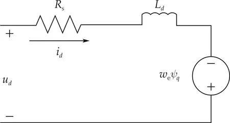
Fig.1 The PMSM equivalent circuit along phase d.
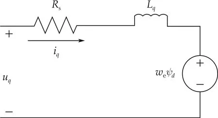
Fig.2 The PMSM equivalent circuit along phase q.
From Figs.1 and 2,the voltage equations of a PMSM are derived as

where the CEMF terms are represented by ωeψqand ωeψd.
The flux linkage along phases d and q are represented by

where ψfis the constant flux generated by the permanent magnets.
The electromagnetic torque is given by

where npis the number of pole pairs.
The torsion equation is represented by

where J represents the moment of inertia for the PMSM,ωmthe mechanical angular speed of the rotor ωm=ωe/np, TLthe load torque, and B the damping coefficient.
We adopt FOC strategy on the speed control system of a PMSM. The FOC structure on PMSM is shown in Fig.3.
In Fig.3,there are three feedback control loops in the PMSM control system:the speed,phase d current,and phase q current control loops. If phase d current idis controlled to be zero, the air gap flux linkage will be equal to the flux linkage of the permanent magnets ψf,and the electromagnetic torque will be only related to phase q current iq. In this case, (2) and (3) could be rewritten as

where Kt= 1.5npψf. Then for phase q current system,the CEMF term would become ωeψf, where ψfis constant.
From(1),we can derive the transfer function for phase q current system as follows:

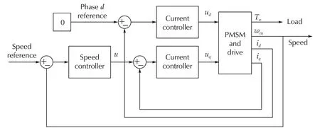
Fig.3 The FOC schematic on PMSM.
As discussed above,we include the CEMF term(ωeψf)into the phase q current system(7)by assuming that idis controlled to be zero. From the Laplace transforms of (4)-(6) and transfer function (7), the block diagram from phase q input voltage uqto the speed output ωmis shown in Fig.4.
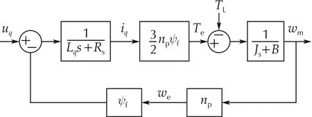
Fig.4 The block diagram between phase q voltage and speed
According to Fig.4, we can derive the following second-order transfer function as the mathematical model for the phase q current control system design.

In (8), the positive coefficients a2= LqJ, a1= LqB+RsJ,and a0=RsB+1.5n2pψ2f.From Fig.4 and(8),we can see that the CEMF term is incorporated in the transfer function model of phase q current system. Particularly the CEMF becomes part of the TLterm(the second term in the right side of(8)),which is to be compensated by a SMC.
3 PMSM control system design
3.1 Phase q current controller design
A modified sliding mode controller is developed on(8) to realize fast and accurate control of phase q current iq.The following assumption is made for controller design.
Assumption 1The load torque TLis bounded that is|TL|≤Tmax<∞,where Tmaxis a positive real number.
The proposed SMC consists of a traditional first-order SMC and a low-pass filter(LPF).The LPF is designed as

After applying the LPF to (8), we can derive the second-order differential equation model of(8)as

Define the phase q current tracking error eqas

where rqis the reference of iq.
Based on(10),a SMC is developed as follows:
Define the sliding surface as

The derivative of the sliding surface sqis

Making ˙sq= 0 and ignoring the load disturbance TL,we obtain the following equivalent control law:

The switching control is designed as

where K is a positive real number. The sign function sgn sqis defined as

The first-order SMC is a combination of switch control law and equivalent control law.It is given by

Substituting(14)and(15)into(17),we have

Next we perform stability analysis by defining the Lyapunov function Vqas

The derivative of Lyapunov function Vqhas the following form:

Substituting(18)into(20),we obtain

The controller gain K is chosen as

Then from(21),we have

Equation (23) shows that the derivative of Lyapunov function is negative definite.Therefore,it is proved that the current control system is asymptotically stable. Invoking Barbalat’s Lemma[27],we can conclude that the variable sqwill converge to zero as time goes to infinity.
3.2 Speed controller design
In this section, we originally apply an alternative ADRC with a reduced-order ESO[23]to the speed system of PMSM to achieve robust control system design.The classic ADRC with a full-order ESO has been broadly used in motion control [24-26]. However, an alternative ADRC with a reduced-order ESO is still an emerging technology,and has not previously applied to the PMSM systems.
Assuming the phase d current idis controlled to be zero,we can rewrite(4)as

Define


where a and b are known parameters and f represents the unknown disturbance.
Equation(24)is rewritten as

where the speed output y=ωmand the speed controller input u =.For a classic ADRC,the system parameter a is considered unknown. Both f and ay constitute a generalized disturbance, which is then estimated by a full-order ESO. In the design of alternative ADRC, we suppose a is a known parameter, and y is measurable.Therefore, only f itself is taken as the generalized disturbance,and is observed by a reduced-order ESO.The alternative ADRC is developed as follows.It consists of a feedback controller and the reduced-order ESO.
A speed controller is designed as

where u0is a virtual controller.
We suppose the disturbance f is estimated and canceled by ˆf.Substituting(29)into(28)yields

Then the virtual controller is designed as u0=kp(r-y),where kpis proportional gain and r is the reference speed signal.Here we select kpas ωcwhich is a positive controller bandwidth.
The disturbance f is estimated by a reduced-order ESO that is derived from a full-order ESO.The full-order ESO is developed as follows:
Define the state variables

Assuming the disturbance f is differentiable,the statespace equations of(28)are written as

The full-order ESO for(32)is represented by

where the state vector z = [z1z2]T, the observer gain vector L=[l1l2]T.The state z1is an estimate of the output y (z1= ˆy), and z2is an estimate of the disturbance f (z2= ˆf). The full-order ESO is used to estimate both speed output y and external disturbance f.
Define the estimation errors as e1= x1-z1and e2=x2-z2.Therefore,the error state vector is e=[e1e2]T.Then the ESO error system is represented by

where the matrix Ae=A-LC.
If the eigenvalues of the matrix Aeare in the open left half plane,the estimation errors e1and e2will converge to zero.The eigenvalues of Aeare computed as

We select both eigenvalues of Aeas-ωo,where ωois a positive observer bandwidth. Then the characteristic equation(35)can be rewritten as

where l1= 2ωo+a and l2=. The observer gains of a full-order ESO for the classic ADRC built on the first-order system are 2ωoand[20]. From (26), a is negative. Therefore, the observer gains for alternative ADRC are smaller than the ones for classic ADRC.
The speed output of a PMSM is typically measurable with the use of an encoder, a tachometer, or a resolver[28].Therefore we assume the speed ωmin(4)is available.Then it is not necessary to estimate the y in(28).The reduced-order ESO is designed as follows.It is utilized to approximate the external disturbance f only.
We can rewrite(33)as

Simplifying(37)yields

Since l1= 2ωo+a and l2=, the reduced-order ESO is represented by

Compared to the full-order ESO in(33),the reducedorder ESO in(39)has simpler structure and thus is easier to implement. Equations (29) and (39) constitute alternative ADRC.
4 Simulation results
We simulate the current and speed control systems of a PMSM in MATLAB/Simulink.The parameter values of a PMSM are listed in Table 1[29].
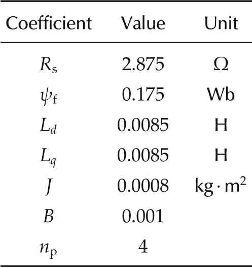
Table 1 System parameters of a PMSM.
In the simulation, we compare the performances of two different closed-loop control systems.For one control loop, the speed system is controlled by the alternative ADRC with the reduced-order ESO, the phase q current is controlled by the modified SMC, and the phase d system is controlled by a PI controller. For the other control loop,only the PI controllers are utilized to control the PMSM’s speed, phase q current, and phase d current.
For SMC and ADRC controlled PMSM system, the control parameters of the ADRC are ωc= 80 rad/s and ωo= 200 rad/s. According to [30], we could tell the bandwidth of the speed feedback loop is 80 rad/s. The control parameter of the SMC is K=5.The proportional and integral controller gains for phase d current are 4.25 and 1437.5.
For the PI controlled PMSM system,the mathematical expressions of the PI controllers are presented in Table 2.From Table 2, the closed-loop bandwidths for phase d current,phase q current,and speed control systems are 500 rad/s,5000 rad/s,and 80 rad/s,respectively(just as explained in[30]).For the fair comparison between the ADRC and PI controller for speed control, the closedloop bandwidth for both control systems are set to be 80 rad/s.

Table 2 PI controllers for a PMSM.
In the first part of the simulation,we test the robustness of two kinds of control systems (one kind with SMC,alternative ADRC,and PI controller,and the other kind with PI controllers only)against load torque disturbances.
The step responses for the phase q current are demonstrated in Fig.5.The reference current is 0.1 A.The load torque disturbance of 2 Nm is added to the system at 5 s. From Fig.5, we can see that the settling time (Ts)for SMC controlled system is 0.001 s (as shown in the zoom-in view), while the Tsfor PI controlled system is 1.6 s. In addition, the SMC controlled system is almost unaffected by the load disturbance.However,the PI controller produces a large overshoot percentage of 112%at t=5 s when the disturbance is added to the system.Therefore SMC shows superior transient performance and disturbance robustness to PI controller.The control voltages of the phase q current are shown in Fig.6. It can be seen that both SMC and PI controller use almost same amount of control effort.
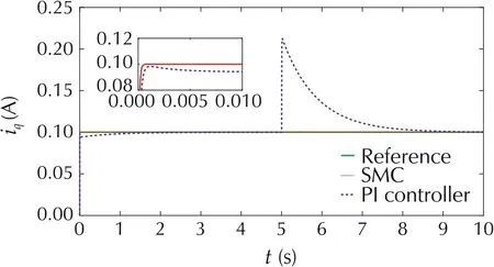
Fig.5 The step responses of phase q current.
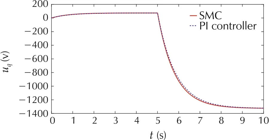
Fig.6 The control voltages for phase q current system.
The step responses for the speed of PMSM are presented in Fig.7. The reference speed is 1000 r·min-1[31,32]. The load torque disturbance of 2 Nm is added to the system at 2 s.Both ADRC and PI controller drive the speed to the reference in 0.05 s.However,after the disturbance is added to the system,it takes much longer time for the PI controller (with a Tsof 3 s) to drive the speed back to reference,compared to the ADRC(with a Tsof 0.5 s).In addition,as t=2 s,the speed response of the ADRC controlled system drops 11.6%which is less than the speed drop of the system with PI controllers.The speed control signals are demonstrated in Fig.8.Both ADRC and PI controller use same amount of control effort till t = 2 s,when the load torque disturbance is added to the system.PI controller requires 38%larger effort than ADRC to compensate the disturbance.
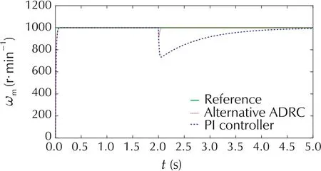
Fig. 7 The speed responses of alternative ADRC and PI controlled systems.
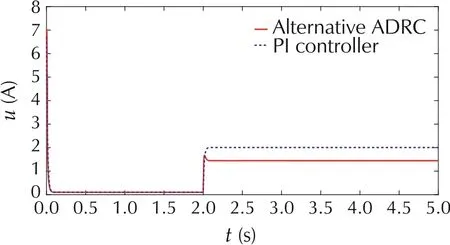
Fig.8 The control signals for speed system.
In the second part of the simulation, the robustness against system uncertainties is tested for the two kinds of control systems.
For phase q current system, the stator resistance Rsis reduced by 50% and the inductance Lqis increased by 50%as suggested in[33].The step responses of the phase q current are demonstrated in Fig.9.In the presence of parameter variations,there is a 4.6%overshoot in the current response of PI controlled system at the beginning of the simulation. In contrast, the SMC controlled response is unaltered with the changes of parameter values.SMC shows much better robustness than PI controller against parameter variations.
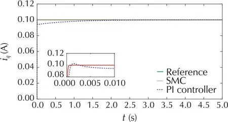
Fig. 9 The step responses of phase q current with parameter variations.
For speed control system, the moment of inertia J is increased by 50% and the friction B is reduced by 50% [33]. The step responses of the speed system are presented in Fig.10. The parameter changes result in a small overshoot percentage of 1.1% in the speed response of PI controller.However,the alternative ADRC controlled system is not affected by the parameter variations.Alternative ADRC demonstrates superior robustness to PI controller against system uncertainties.
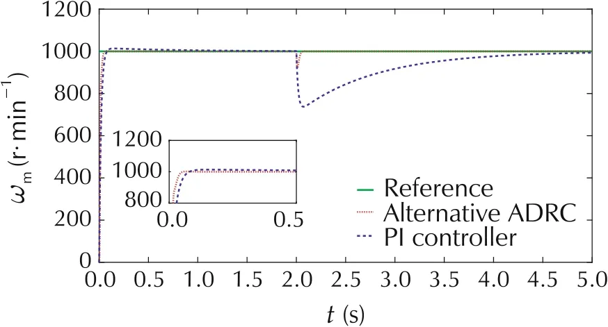
Fig.10 The speed responses with parameter variations.
In the third part of the simulation,the performance of classic ADRC is compared with alternative ADRC.
The speed responses of the PMSM system under the control of both ADRCs are demonstrated in Fig.11.Both controllers drive the speed to the reference in 0.1 s.After the disturbance is added to the system at t = 0.2 s, the speed response of alternative ADRC drops 1.9% less than that of the classic ADRC. Therefore, alternative ADRC shows slightly better transient performance and robustness(against disturbance)than classic ADRC.The control signals of alternative ADRC and classic ADRC are illustrated in Fig.12.It can be seen that both ADRCs use almost same amount of control effort.
To test the robustness against parameter variations,the moment of inertia J is increased by 50% and the friction B is reduced by 50%[33].The speed responses of the PMSM system under the control of both ADRCs are presented in Fig.13. It can be observed that classic ADRC produces 1%overshoot in speed response.However,alternative ADRC drives the speed to the reference without overshoot. Compared to classic ADRC, the alternative ADRC shows better robustness against system uncertainty.The control signals of alternative ADRC and classic ADRC are demonstrated in Fig.14.It can be seen that both ADRCs use almost same amount of control effort.
From the simulation results, we observe that the alternative ADRC is more robust against disturbance than PI controller in speed control. In addition, the modified SMC is superior to the PI controller in terms of transient performance and disturbance robustness for phase q current control.Both modified SMC and ADRCs are robust against parameter variations.Particularly the alternative ADRC has better transient performance than the classic ADRC.
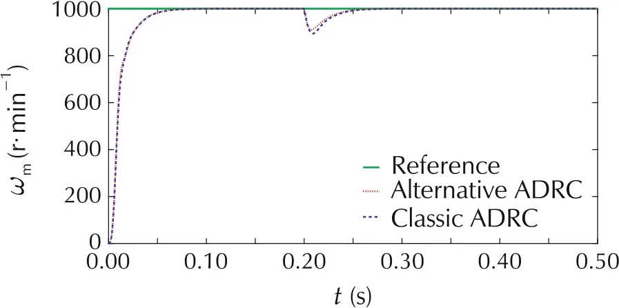
Fig. 11 The speed responses of PMSM with alternative and classic ADRCs.
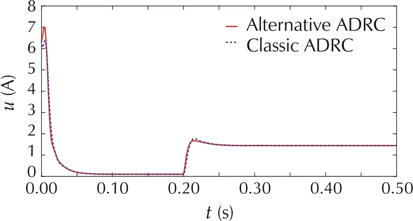
Fig.12 The control signals of alternative and classic ADRCs.
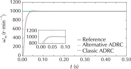
Fig.13 The speed responses of ADRC controlled systems with parameter variations.
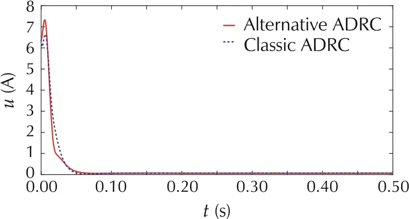
Fig. 14 The control signals of both ADRCs with parameter variations.
5 Conclusions
A novel second-order mathematical model of the phase q current system is proposed.In this new model,the unknown nonlinear CEMF is considered.A modified SMC is originally developed and applied to the phase q current system.The modified SMC is easy to implement in the real world with only one tuning parameter. The stability of the phase q current control system is proved theoretically. In addition, an alternative ADRC with a reduced-order ESO is initially designed for the speed control system of a PMSM to achieve robust speed control system. The alternative ADRC focuses on rejecting the unknown disturbance while using the partially known system information. It successfully reduces the complexity of control design and shows better transient performance than classic ADRC.The simulation results verify the effectiveness of the SMC and ADRC combined control system on the PMSM. They also demonstrate the robustness of the control system against load disturbances and system uncertainties.Both SMC and ADRC produce better performances in step responses than PI controllers.
In summary, the novelties of the proposed research are: 1) an original second-order ODE model for the phase q current system of a PMSM,2)a modified SMC with only one tuning parameter for current control,and 3) an alternative ADRC with a reduced-order ESO for speed control.
For future research, we plan to implement the proposed SMC and ADRC to a real PMSM system, and conduct hardware experiments to test the controllers in practice.
杂志排行
Control Theory and Technology的其它文章
- An overview of various control benchmarks with a focus on automotive control
- JSAE-SICE benchmark problem for vehicle dynamics control
- SICE benchmark problem:starting speed control of SI engines
- Revisiting the benchmark problem of starting control of combustion engines
- Control of the common rail pressure in gasoline engines through an extended state observer based MPC
- Introduction to the benchmark challenge on common rail pressure control of gasoline direct injection engines
