JSAE-SICE benchmark problem for vehicle dynamics control
2019-05-08YutakaHIRANO
Yutaka HIRANO
Toyota Motor Corporation,1200,Mishuku,Susono,Shizuoka,410-1193,Japan
Abstract Recently many new types of small vehicles for future urban societies have been proposed and developed.Such small vehicles tends to have reduced stability and handling ability than conventional vehicles because of their lighter weight and reduced tire performance. To cope with this problem by active collaboration of Japanese academia and industries, a benchmark problem of designing vehicle control logic for an articulated In-Wheel-Motor vehicle was settled by Japanese society of automotive industries and academia.For this purpose,simulation models of the new vehicle using multi-physics acausal modeling language Modelica were provided from the industry side.Challengers were requested to design controllers of tire steering angle,tire camber angle and tire driving force to satisfy requested vehicle dynamic characteristics. There also were some restrictions about the range of actuators.Four test scenarios were given to evaluate the control performance.Many challengers from Japanese Universities have tackled with this benchmark problem.Some results of their researches are also introduced in this paper.
Keywords: Automotive control,vehicle dynamics,future mobility,stability and handling performance,modeling and simulation,Modelica
1 Introduction
From demands for a low carbon society,motorization of automobile power systems is progressing.As a countermeasure in vehicle systems, the miniaturization and weight reduction of vehicles and the adoption of low RRC (rolling resistance coefficient) tires are progressing. In addition, as a power system of new mobility,a four-wheel in-wheel motor (IWM) method has been proposed, which has a minimum installation space on the vehicle body and possibility of innovative packaging[1].On the other hand,with such new mobility,it is expected that the movement of the vehicle is more susceptible to disturbance due to the reduction of the tread and the wheel base and the reduction of the weight of the vehicle body as shown in Fig.1. In addition, in the case of the low RRC tire,the control performance against the lateral motion tends to decrease as compared with the conventional tire for structural reasons.In the small new mobility,there are concerns about deterioration of disturbance stability and emergency avoidance performance due to tire size restrictions as well.
To solve this problem,the author set up a benchmark problem for industry-university collaboration as a member of a joint committee of JSAE(Society of Automotive Engineers of Japan)and SICE(Society of Intrument and Control Engineers) in Japan [2-4]. This paper aims to introduce this benchmark problem about the vehicle dynamics control and also a brief summary of the results from academic side.In this paper,purpose and setup of the benchmark problem is described.Next,the Modelica model of the new small EV with IWM driving system is explained. Finally brief summary of the researches proposed from several Universities are introduced.
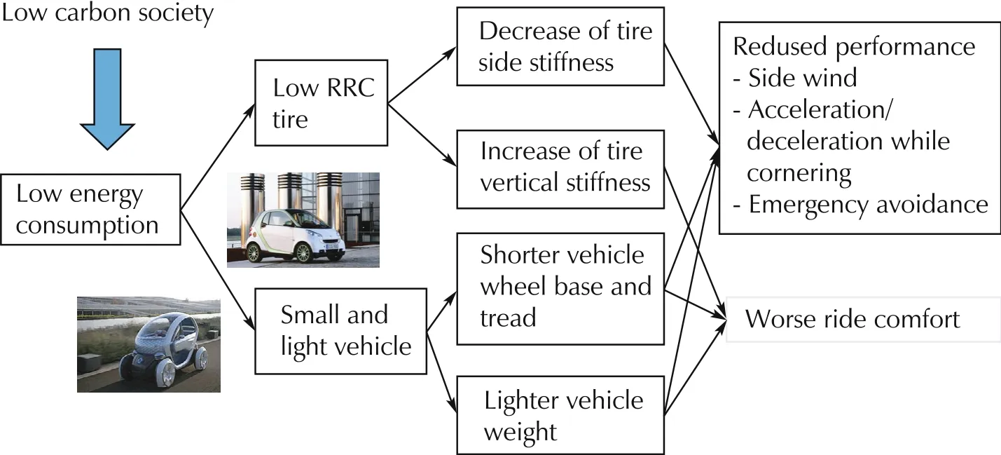
Fig.1 Problems of small light vehicles with economic tires.
2 Background and purpose of the benchmark problem
By the reasons shown in Fig.1, it was expected that such small and light-weight vehicles equipped with low RRC tires will be less stable than the conventional vehicles against strong side wind. To confirm this assumption,a side wind test was simulated for both a conventional vehicle and a small and light vehicle. A vehicle model mentioned in Section 3 was used.The specifications of both vehicles are as shown in Table 1.
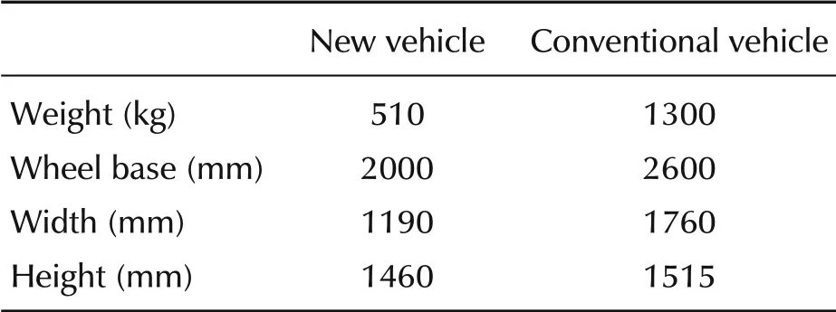
Table 1 Specifications of vehicles.
Test condition was to run across a zone of side wind of 20 m/s while running at 60 km/h. The steering angle was fixed to zero degree. Fig.2 shows the result of the simulation. It was confirmed that the small and light vehicle was less resistive than the conventional vehicle against the side wind.
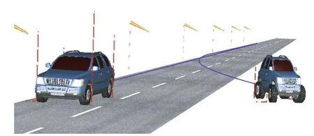
Fig.2 Animation result of side wind test.
Upon above backgrounds, the benchmark problem was settled to research control system design for such a small and light vehicle equipped with four wheel IWM.The vehicle characteristics of the small and light vehicle used in this benchmark problem are as follows.
The tire characteristics are such that it is necessary to control the steering angle and the camber angle at the same time in the range of motion where a large lateral force is required.On the other hand,as shown in Fig.3,the component force of the side force also acts as running resistance with respect to the traveling direction.Accordingly,if the tire slip angle is excessively increased by the steering angle control,the running resistance increases, which is disadvantageous in terms of energy consumption. The lateral force of each wheel nonlinearly changes in conjunction with the steering angle and the camber angle by the control and also affected by the slip angle caused by yaw moment control. In addition,each actuator was restricted in the operating range.The present benchmark problem is to optimize the steering angle, the camber angle, and the driving/braking force of each wheel thereby achieving desired vehicle motion performance with minimum energy consumption.Consequently the problem setting is redundant and interfering as described above.
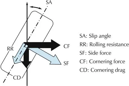
Fig.3 Tire force.
This problem was announced to the wide area of academia as one of the benchmark studies settled by JSAE and SICE about “vehicle modelling and control research” in Japan. Anyone who wishes to challenge this benchmark study can freely obtain the model library from the web site below. The simulation model was constructed using Dymola, one of the simulation tool using Modelica language (http://cig.ees.kyushuu.ac.jp/benchmark_JSAE_SICE/).
3 Simulation model
3.1 Vehicle model
A simulation model of the small size electric vehicle was provided from the industry side using multi-physics and equation based modeling language Modelica.About the details of Modelica,please refer to the web page of Modelica Association(https://www.modelica.org/).
The configuration of the vehicle model provided for this benchmark problem is shown in Fig.4. The details of the vehicle model is shown in Fig.5. Models of car body,suspension,tire,IWM and its electric drive system are provided by the model of heterogeneous physical system modeling language Modelica. Both body motion and suspension motion are modeled as a threedimensional multi-body mechanism system.As the control mechanism of the steering angle and the camber angle in the front and rear suspension,the lower arm of the double wishbone suspension is made to be two parallel links as shown in Fig.6 and by changing the length of the lower arms independently,the steering angle and the camber angle can be controlled independently [5].“Pacejka02”magic formula model[6]was used as a tire model.Also a simple electric model of battery and IWM is included to calculate energy consumption of IWMs inside the power train model.
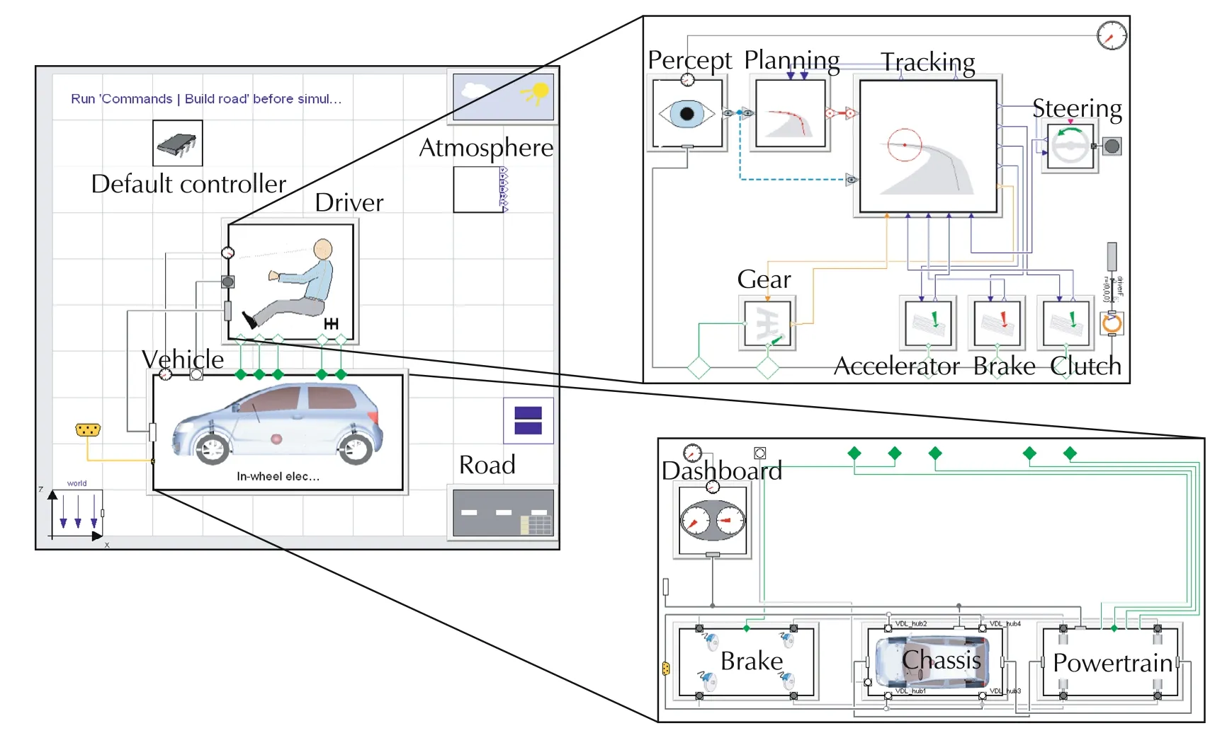
Fig.4 Top layer of the simulation model.
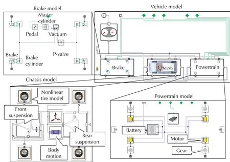
Fig.5 Structure of the vehicle model.
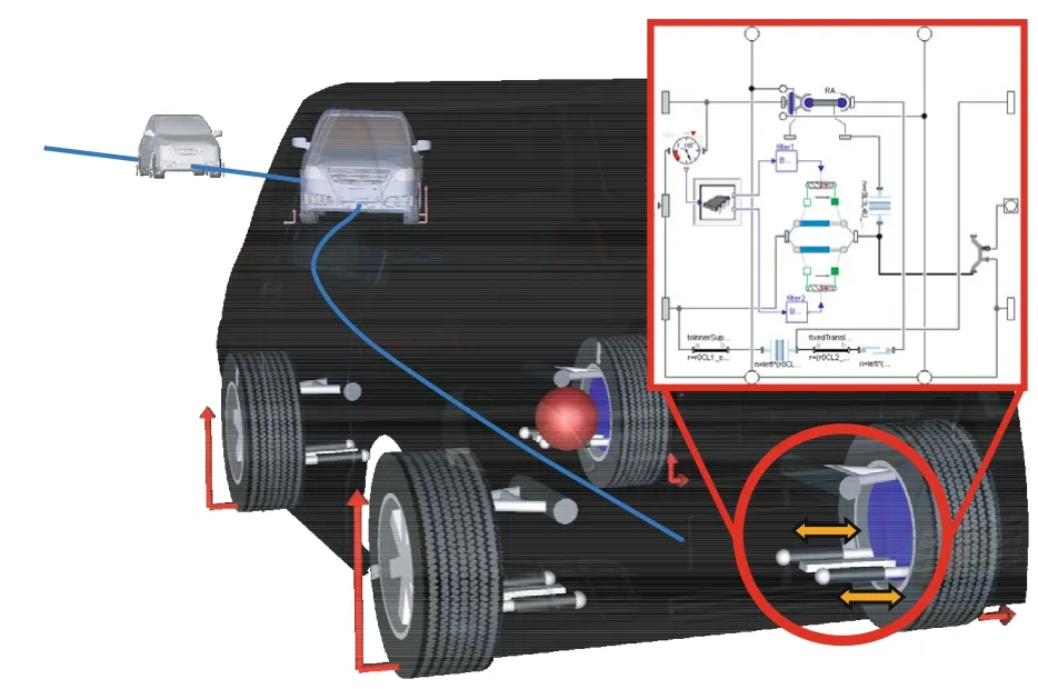
Fig.6 Suspension model.
There is a simple battery model which considers only inner resistance and constant voltage generation. Electricity is provided to each DC motor and the motor converts electric current to driving/braking torque of each wheel by the following equation:

where τiis the motor torque,Kmis a constant,and iiis the motor current.
Power consumption of each motor is calculated by a multiplication of the battery voltage and the current flowing into the each motor.
3.2 Description of required tasks
The challengers of this benchmark problem were requested to design the controller and implement it in the model.It was required to challengers of this benchmark study to satisfy the following demands.
1)Make the vehicle motion(yaw rate and side slip angle)follow the desired characteristics.Also make a deviation from desired path to minimum. Each task should be done under the limited control amounts of steering angle and camber angle of each wheel as shown in Table 2.

Table 2 Limits of actuators for each wheel.
The desired yaw rate and the desired slip angle are given as below.
Desired slip angle:

Desired yaw rate:

Here,Ksand Tsare settled from the desirable motion of the conventional vehicle as follows:

where
af:longitudinal distance between front wheel and center of gravity(CG);
ar:longitudinal distance between rear wheel and CG;
cf:cornering stiffness of front two tyres;
cr:cornering stiffness of rear two tyres;
M:mass of vehicle;and
V:vehicle speed.
2) Minimizing energy consumption of IWMs is required whereas no limitation for driving and braking torques of each IWM is applied.
Four test scenarios were given as bellow.
a) Accelerating while cornering on a low friction road: Accelerate the vehicle from initial speed 0 km/h to 70 km/h in 5 seconds on a slippery (coefficient of friction(μ=0.6)curve of R=50 m as shown in Fig.7.
b) Decelerating while cornering on a sprit friction road:Decelerate the vehicle from initial speed 70 km/h to 0 km/h in 5 seconds on a slippery split μ(μ=0.9,0.4)curve of R=50 m as shown in Fig.8.
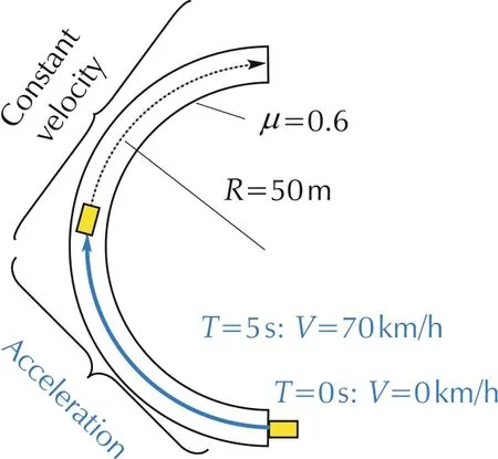
Fig.7 Test scenario 1:Acceleration while cornering.
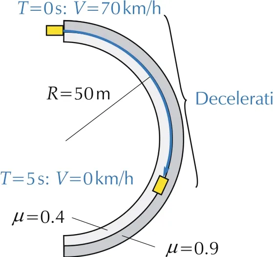
Fig.8 Test scenario 2:Deceleration while cornering.
c) Double lane change: Perform ISO double lane change task at the speed of 70 km/h as shown in Fig.9.
d) Crossing side wind: Run straight at the speed of 70 km/h while crossing strong side wind area as shown in Fig.10.
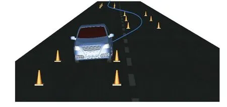
Fig.9 Test scenario 3:ISO double lane change.
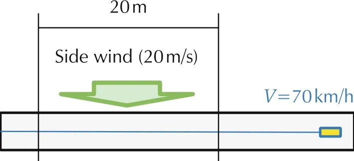
Fig.10 Test scenario 4:Side wind test.
3.3 Controller model
A sample controller (default controller) is also provided.As a tentative example,the default controller calculates commands for the actuators as bellow.
Front steering angle:

where Gsis the steering gear ratio.
Rear steering angle:

Camber angle of all wheels:

Driving/braking torque:

where
Ktorque:constant;
acc_cmd:acceleration command(0 to 1);
brk_cmd:brake command(0 to 1);
Kp:proportional feedback gain;
Ki:integral feedback gain;and
Vref:desired vehicle speed.
Every challengers were requested to modify this default controller to fulfill the requests.
4 Results of the researches from the challengers
In this section, some results of the researches by the challengers from Japanese academia are introduced.Many kinds of the solutions were proposed as mentioned below.
Nishimura et al. from Keio-gijuku University tried to identify a simplified transfer function of the plant from the provided full vehicle model and then applied H∞control to trace the desired dynamics[7].Fig.11 shows the proposed H∞controller.
Nonaka et al. from Tokyo City University proposed a method utilizing model predictive control (MPC) and sliding mode control (SMC) [8]. They at first linearized the non-linear plant and designed MPC for tracking the desired dynamics and also satisfying the limitation of the actuators. They applied SMC to control the actual actuators in the full vehicle model to realize the ideal motion of the actuators calculated by MPC.
Asai et al. from Nagoya University proposed a hierarchical control of the non-linear and redundant system [9]. Fig.12 shows the hierarchical controller by them. They also reported an advanced research of the control for redundant systems by applying approximate inverse transform of multivariable functions[10].
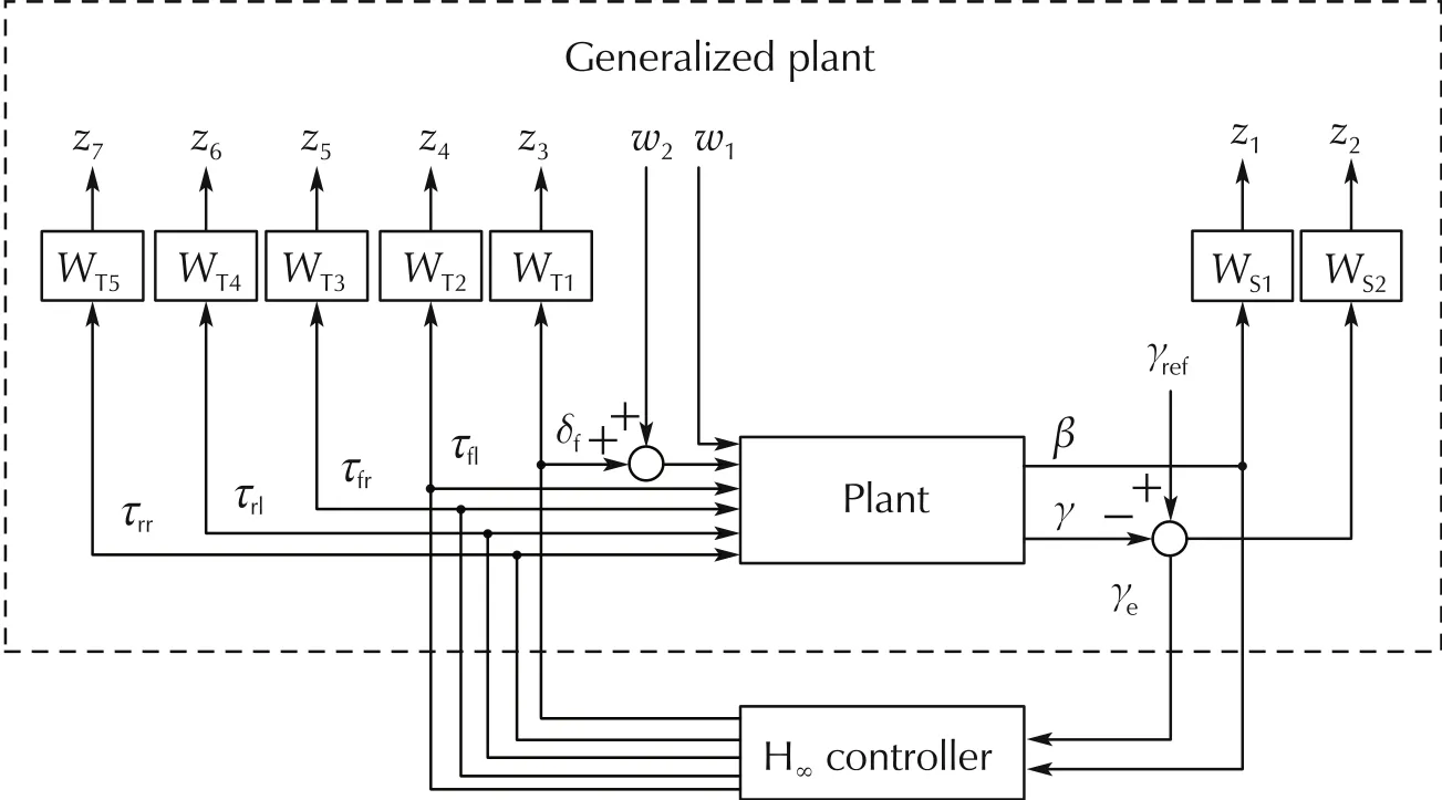
Fig.11 H∞controller.
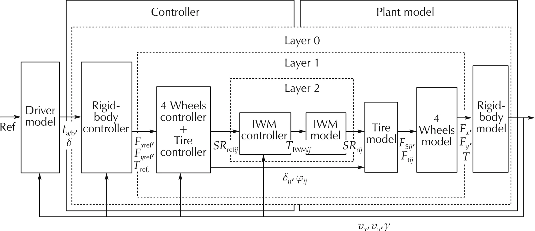
Fig.12 Multiple layer controller.
Kawabe et al.from Kyushu University proposed a nonlinear MPC considering the non-linear characteristics of tires as shown in Fig.13 and Fig.14[11].
About the details of the researches from each challenger,please refer to the papers introduced in the reference section.
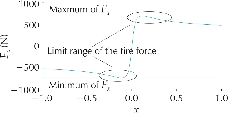
Fig.13 Limit range of tire forces.
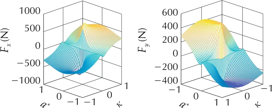
Fig.14 Plot of tire forces.
5 Conclusions
To accelerate the collaboration by industries and academia about the researches for automotive control,JSAE-SICE benchmark problems for automotive control were established.The author proposed one benchmark problem about optimizing redundant system of vehicle dynamics and energy consumption. Many Japanese Universities challenged against this benchmark problem and many interesting researches were proposed.
By the activity of the benchmark problem,control researchers of academic side could accelerate understanding about actual vehicle engineering and also demands of the industries. On the other hand, the industry side could know the cutting-edge theories and technologies of system control.Also it was helpful to let the students think about working in the automotive industries.Thus,the benchmark problem was useful for both academic and industry sides. It is expected that the collaboration between academia and industries will become more active by utilizing the benchmark problem.
杂志排行
Control Theory and Technology的其它文章
- An overview of various control benchmarks with a focus on automotive control
- SICE benchmark problem:starting speed control of SI engines
- Revisiting the benchmark problem of starting control of combustion engines
- Control of the common rail pressure in gasoline engines through an extended state observer based MPC
- Introduction to the benchmark challenge on common rail pressure control of gasoline direct injection engines
- Rail pressure controller design of GDI basing on predictive functional control
