SICE benchmark problem:starting speed control of SI engines
2019-05-08JunichiKAKO
Junichi KAKO
Advanced Powertrain Planning&Management Div.Toyota Motor Corporation,Shizuoka,Japan
Abstract Starting the engine and quickly adjusting the engine speed to the target value after that will always be a challenge for vehicles with an internal combustion engines at development sites in the automotive industry.The SICE Research Committee on Advanced Powertrain Control Theory provided this task as a benchmark problem with the engine model. Just as control developers in the industry are provided actual engines, many of the academic experts have acquired engine models, analyzed behavior and constructed controls,and solved control tasks.We summarize this activity by explaining the methods by many challengers that achieved the target performance.
Keywords: Engine start control,benchmark problem,engine model
1 Introduction
Automobiles gained satisfaction from users by realizing good quality and low price, balancing the requirements of running pleasure,environmental performance,safety, reliability, convenience and comfort at a high level.As a result,so many vehicles are used around the world.
As the number of cars is expected to increase further on a global scale, it is necessary to satisfy higher requirements on automobiles especially for environmental performance and safety.According to the forecast of greenhouse emissions reported by Intergovernmental Panel on Climate Change in 2014, it is expected that the earth surface temperature will rise by 3.7 to 4.8°C and that significant influence of climate change will occur worldwide if CO2emissions continue to increase due to an increase in the number of cars, etc. It is said that it is necessary to keep the temperature rise to less than 2°C in order to minimize the influence.For this,it is necessary to reduce CO2emissions rapidly and ultimately to reduce it to below zero. There is no time to lose.
Regarding the power source that realizes running performance of cars,in the early 20th century automobiles using only internal combustion engines like gasoline and diesel engines were main stream.At the end of the 20th century, hybrid cars and battery electric cars resurrected.The plans to advance the electrification of power trains by them and fuel cell (FC) and regulations promoting it were announced in each country and city.However, from the viewpoint of convenience, the constraints of energy supplied (fossil fuel, electricity, hydrogen,etc.),and the above-mentioned increase in the number of automobiles worldwide,there is no early replacement to electric motorization.It is expected that the change will be gentle. According to Energy Technology Perspectives 2012 by the International Energy Agency(IEA),though the electrification is going on,vehicles using internal combustion engines using gasoline, diesel fuel, gas such as CNG/LPG, and hybrid power trains combining them with motors used as power sources will continue to increase until around 2040.That means that it is necessary to develop complicated power trains including the internal combustion engines and to introduce them into market.
Regarding power train control, it is necessary to satisfy the above-mentioned requirements,and the necessity of introducing the latest control studied in academia is increasing.In order to strengthen the cooperation for that, The SICE (The Society of Instrument and Control Engineers) Research Committee on Advanced Powertrain Control Theory was founded in 2006. In addition,we have been expanding our activities as a joint committee between JSAE (Society of Automotive Engineers of Japan) and SICE since 2010. This Joint Committee is called “Joint Committee for Automotive Control and Model Research”in SICE,and called“Automobile Control and Model Research Division Committee” in JSAE.These committees provide control issues in the automobile industry as several benchmark problems together with plant models to academia. In this paper, we introduce the engine cold start problem that we first announced and evaluate the activities of the benchmark problem by explaining the challenger’s approach.
2 Provided engine model
The supplied engine model [1-4] simulates an existing engine. The engine is a V-type six-cylinder spark ignition engine with a displacement of 3.5 liters, and it has a feature that it has a port fuel injection injector in each intake port and a cylinder fuel injection injector in each cylinder (Fig.1). The intake port injector aims to reduce unburned discharge HC(Hydro Carbon)by promoting atomization of fuel and the in-cylinder injector aims at increasing the intake air amount by reducing the intake air temperature.It is necessary for the intake port injector to inject fuel at a timing at which the fuel can flow into the cylinder before the intake valve is closed,in contrast the in-cylinder injector can inject fuel even after the intake valve is closed as long as it is before spark ignition timing.Nevertheless,in this problem setting, only the intake port injection is effective, and the use of in-cylinder injector is prohibited.
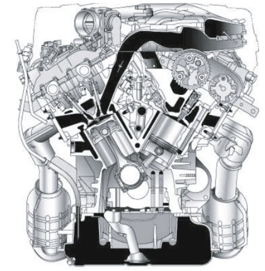
Fig.1 Targeted V6 SI engine.
The concept of the plant model we normally build is shown in Fig.2. The models made only with the physical laws such as mass conservation law basically do not have adjustment parameters,so in a simple system they show correct behaviors, but in complicated systems they may operate in a way that deviates from the real phenomenon.A statistical model(empirical model)aiming to simulate the behavior of a plant requires adjustment of many parameters in order to make the operations consistent.What we usually aim for is a quasiphysical model(approximated physical model)that uses the physical law for the skeleton of the model to reduce the adjustment parameters while matching with the behavior of the actual plant.However,the provided plant model incorporates as many physical laws as possible,and the plant model can be viewed and analyzed in detail. As a result, as same as controller developers in enterprises,challengers can make detailed analysis and can make control designs by using the plant models as controlled objects.
The provided simulation model is built in SIMULINK,and the first hierarchy of the model is shown in Fig.3.As a plant,the engine body is modeled as one block of sub-model, and the starter and the controller are separately modeled. The engine body has four inputs: ignition timing, injected fuel amount, throttle angle and starter torque,and the amount of throttle passing air and the crank angle, the intake pipe pressure, and the engine speed are output.The throttle passing air amount,the crank angle, and the engine speed are input to the controller block, and the controller block outputs the throttle angle,injection fuel amount,and ignition timing instruction value calculated by the controller.The Scope block is connected to the engine block so that four outputs of the first cylinder are displayed,and those outputs can be confirmed even during the simulation.
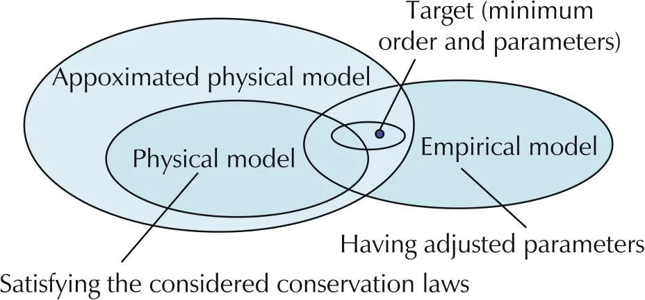
Fig.2 Plant modelling concept.
As shown in Fig.3, the provided engine model consists of the engine block,the control block and the starter motor block. The inputs of engine are the throttle angles,the amount of the injected fuel mass and the spark advance of all the cylinders.The crank angle,the engine speed and the air flow rate through the throttle valve are fed to the controller. The inputs and the outputs of the controller are specified in the control block and can’t be changed by a challenger. The challengers must put their controllers in the control block.The scope block is added to monitor the engine speed,the intake pressure,the air flow rate through the throttle valve and the crank angle of the cylinder 1.
Inside of the engine block consists of four blocks of throttle valve, intake system parts, cylinder peripheral parts,crank peripheral parts(Fig.4).The outside of the throttle valve faces the atmosphere,and the air response up to the inflow into the cylinder is simulated in the intake system component block. The cylinder peripheral component block constitutes a V-type six cylinder engine, considering the behavior of the fuel injected at the port of each cylinder and behavior of the in-cylinder pressure at each crank angle.The gas flowing in from the intake system burns and is discharged from the exhaust valves.As with intake system,the exhaust system is connected to the atmosphere at the port outlet.In the cylinder block,the pressure in the combustion chamber,the gas flow rate passing through the intake/exhaust valve,etc.are calculated for each crank angle.The force transmitted from the pressure in the combustion chamber to the crankshaft is calculated and the engine speed is determined.The crankshaft is not connected to a power transmitting system such as a transmission. Other version of the model is provided so that the challengers can understand the cold start engine speed behavior when the throttle angle, the spark advance and the injected fuel mass are constant. It can be useful for the challengers to understand the purpose of the designed control in the benchmark problem well.
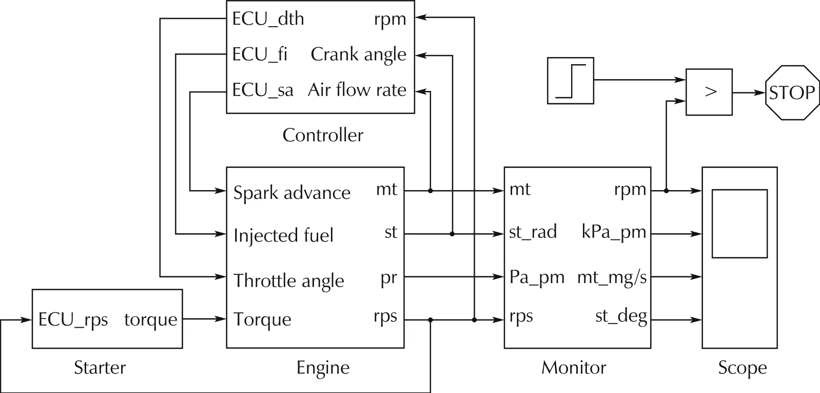
Fig.3 Simulation model.
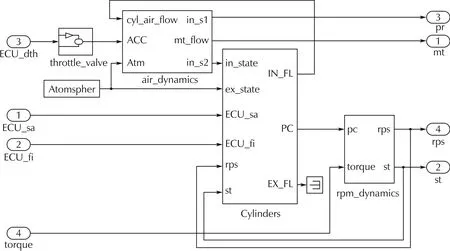
Fig.4 Engine model.
An example of engine starting in this simulation model is shown in Fig.5.
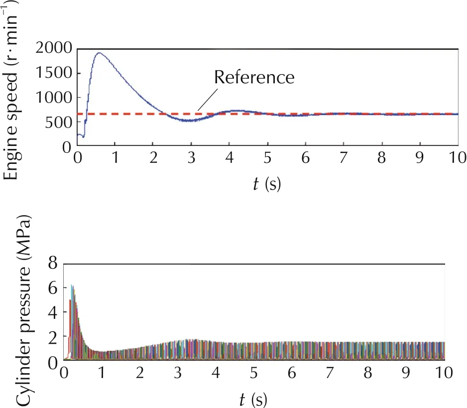
Fig.5 Example of the engine start.
In this example, the engine speed before the start of combustion (ignition) is controlled at 250 r/min by the starter motor,and after ignition the air-fuel ratio,which is the mass ratio of air to fuel,throttle angle,and spark ignition timing are controlled to hold the engine speed to 650 r/min. As shown in the formula (1), the fuel injection amount is controlled to the theoretical mixture ratio with respect to the amount of air sucked into the combustion chamber during the intake stroke.

The behavior of the engine speed shows rapid rising after the first combustion(ignition)and then settles down to 650 r/min with relatively small gradient.Since the intake system before engine start is at atmospheric pressure,and the amount of air intake by the engine is larger than that at idle for several cycles after engine start, large torque is generated with the air fuel ratio and ignition timing described above. As a result, the engine speed overshoots immediately after engine start as illustrated.
3 Problem setting
The target of this benchmark problem is to start the engine and control the engine speed to a constant 650 r/min in the shortest time, using the model shown above.The solid line in Fig.6 shows the boundary,and it is necessary to control the engine speed so that it does not violate the gray area.The broken line is the control target value 650 r/min of the engine speed.
The required criteria in steady state:
a)Closed-loop stability.
b)The engine speed has converged to 650 r/min.
c) The engine speed has reached 600-700 r/min within 1.5 seconds from engine start.
The required criteria in transient state:
d) Overshooting of engine speed should be sufficiently suppressed.
e)Hunting does not occur.
These requirements need to be realized regardless of the crank angle position of the engine at startup.
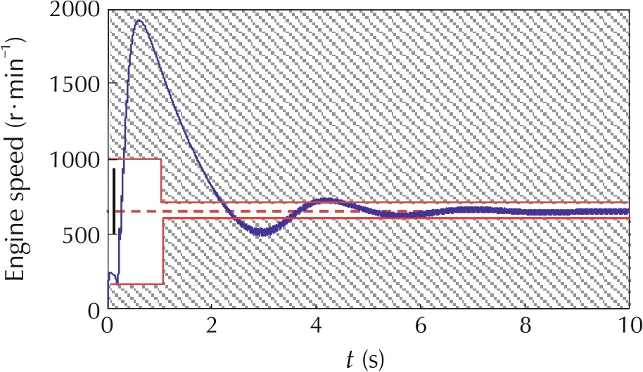
Fig.6 Requirement on engine speed.
4 Characteristics of the problem
There are four engine states: combinations of firing and misfiring, and starter motor drive and stop. In order to shift the engine state from misfiring to firing,the air-fuel mixture in the cylinder needs to be in a predetermined range (see Equation (2)). If this condition is not satisfied,the engine will not be in firing(Fig.7).
When the engine is“firing”,engine rotation is stable but nonlinearity is strong. When the engine is “misfiring”,the engine is unstable and it leads to engine stop.Therefore, in order to control the engine speed to the target value, it is necessary to control to maintain the“firing”state.

The next feature is that the inputs for engine speed control are redundant.
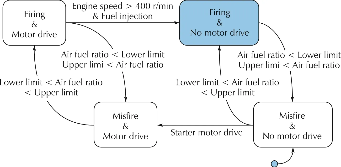
Fig.7 State transition of engine behaviour.
Throttle opening angle, fuel injection quantity, ignition timing,etc.can be considered as inputs that affect the engine speed. Although throttle opening angle can change engine torque in both of increasing direction and decreasing direction,the response is slow because of the mechanism that changes the amount of air at the throttle position away from the cylinder.
Regarding fuel injection amount and ignition timing,torque decrease direction is the main adjustment direction, but the response is quick. In particular, ignition timing can adjust combustion timing directly, so the response is very quick. The torque adjustment by fuel injection amount is accompanied by the change of the air-fuel ratio at the same time, and the engine exhaust gas concentration and the gas temperature change.With regard to the change of the exhaust gas concentration,there is a demerit that the exhaust gas purification ability of three-way catalyst located in the downstream is greatly deteriorated if the air-fuel ratio is out of the theoretical mixing ratio. Regarding ignition timing, torque reduction by delaying (retardation) is a usual method,but when torque is greatly reduced, the unburned fuel components react in the exhaust pipe and it brings high exhaust temperature, and parts protection enrichment is required. In normal engine control, ignition timing is delayed to improve responsiveness while securing necessary torque by throttle angle control. It is a basic strategy to minimize the use of ignition timing delay.
The purpose of each input is summarized as follows from the viewpoint described above.
1)The fuel injection:air fuel ratio control.
2)The throttle angle:fuel consumption.
3)The spark advance:rapid engine speed control.
Fig.8 shows the control structure constructed with the concept above.Throttle opening angle is specified by assuming the torque required by the driver from the accelerator pedal angle and considering the engine speed.
The amount of air flowing into the cylinder including the transient state is predicted from the amount of intake air at the upstream in the intake system,the engine speed,and the throttle angle,and the in-cylinder target fuel amount is calculated from the target air-fuel ratio.The amount of injected fuel is determined considering the fuel that adheres to the port once and flows into the cylinder later. The ignition timing is determined from the air volume and the engine speed.
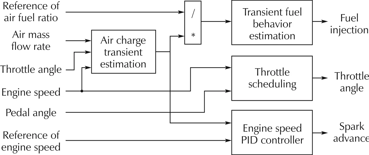
Fig.8 Common engine control structure.
The engine model can be expressed by the following form generally.

where x is the state and u is the input.

Now,θ is the crank angle and ω is the engine speed.Using equation (4), the engine model can be changed from a time-varying system to a discrete system expressed by crank angles desired for control of the engine.However, at low engine speeds, the control frequency is lowered,so that the controllability may be degraded.It can be said that this is one of the reasons why it is difficult to suppress the overshoot of the engine speed immediately after the start of engine.A way to avoid this problem is to control by feedforward.
Fig.9 shows an example of the control strategy in this benchmark problem. It needs to change with time from the starting timing of engine start control. In an engine,although it is discrete control that injects fuel to each cylinder and ignites it, it is a time-variant physical phenomenon that the intake air changes at the time of startup.It is necessary to consider both.
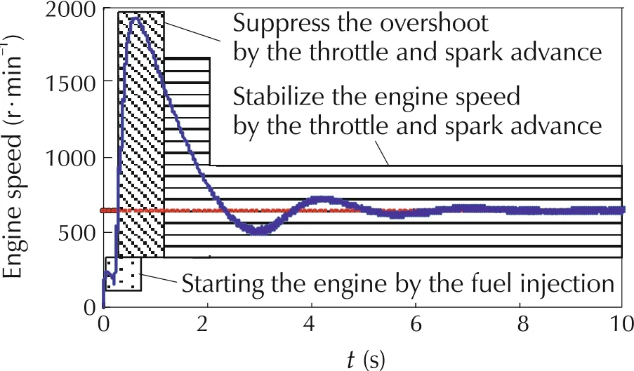
Fig.9 An example of engine control strategy.
Again, the features of this problem are summarized as follows:
1)Transition between stable state and unstable state.
2)Redundancy of input variables.
3)Continuous time and discrete event system.
4)Control strategy change depending on time.
5)Combining feedforward and feedback.
From these features, it can be said that this problem cannot be solved with only one method,but a combination of several methods is required.In fact,a couple of examples where advanced controls were applied have been reported [5]. Engine speed control in idle mode is a simple task that can be controlled within the range of linear control. However, the issues we are dealing with this time cannot be solved simply by one method,and we need to combine different methods to solve the problem.Engineers in the automotive industry need to address this type of complex task, and to simplify the control design for complex control objects or complex control target,control system design is performed as a simple combination of controls. It is an approach that simplifies the complexity. The academic community provides simple tasks in education. As mentioned above,this problem was adopted paying attention to the difference between the approaches for control development in industry and academia.
Fig.10 is an example of the control result by the control constructed based on the control structure shown in Fig.8 and the control strategy shown in Fig.9.Although the start-up is somewhat slow,good control results are obtained generally, and it can be seen that the requirements of the task are satisfied.
However, in the general market all over the world,robust start ability is required against characteristic changes due to differences in fuel (such as composition), variation of engine friction caused by variation of individual engine and aging effect, and variations of components such as intake valves that may occur in the real market. Ensuring reliability in the market is a very complex matter,and usually it requires a great deal of development and verification time to achieve that.Moreover, there are many cases where this improvement in robustness is in a trade-off relationship with other requirements(e.g.,exhaust gas reduction).A more efficient and accurate control design is highly desirable.
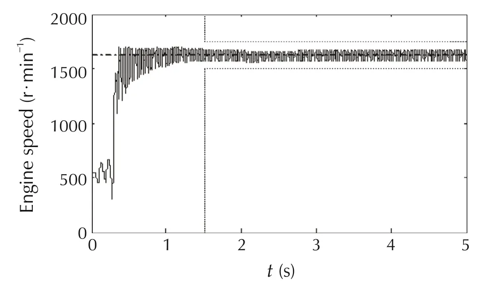
Fig.10 An example of control results.
5 The analysis and results of challengers
Many challengers to this day have challenged this engine start benchmark problem to this day. We will focus on the results of the 36th SICE Symposium [6-12]reported by 7 challengers. Almost all challengers have succeeded in starting the engine, but some overshoots of the engine speed, which can be used as an indicator of stability assessment, still have room for further investigation. Their approaches can be divided into the following classes:
A:Analyze the model to recognize the physical background and rebuild the model equation.
B: Partially adapting advanced control theory (standard method often used in industry).
C: Constructing the feed-forward control using the result of investigation of time series optimum value of inputs and combine it with feedback.
D: Combining the simulation data with conventional control structures.
E:A bold approach using the“misfire”condition.
It is worthy that Challenger A challenged to analyze the engine model,which is a very time-consuming and specialized method.They challenged the analysis knowing that the engine model is very complex and has discrete characteristics and strong nonlinearities.Although there are examples that have not achieved expression of appropriate formulas, time and effort will lead to find ways to simplify model formulas or to facilitate model calculations from computer science and information theory.
Challenger B seems to be the most promising from the industrial point of view.Physical considerations are very useful and will show the effectiveness of advanced control.One challenger has very carefully analyzed the timing of measurement and control,which is a very important task in control design.
Challenger C succeeded in starting the engine and stabilizing the engine speed, but struggled to get good results. Optimal value search always involves the risk of falling into local optimum values and not reaching the global optimum input profile. In addition, if “misfire” occurs after feedback started, control cannot be performed well.This approach can clarify the optimum values of throttle angle and fuel injection amount, ignition timing,and it is very attractive.Moreover it can be extended to add constraints such as minimizing HC exhaust gas while warming up the catalyst.One challenger has optimized the fuel injection amount and ignition timing profile while maintaining a constant throttle angle.In addition,other challengers have simultaneously optimized 3 input profiles by numerical optimization. This challenger has a basic strategy to start the engine only by feed forward,but has realized that it is necessary to add feedback from appropriate timing.
Challenger D applied a data-based approach in estimating in-cylinder inflow air volume. Although the results are good, the method is so different from normal approaches that it is difficult to understand the physical background of the method at this point.We need to analyze why it is good and keep an eye on the progress.
The idea of taking advantage of the“misfiring”condition of Challenger E differs greatly from the idea of trying to keep the “firing” condition of other challengers, and stimulates us beyond our image. Their idea also leads to variable cylinder number control, which is one of the methods to improve fuel consumption. In fact, this method can certainly suppress the overshoot of the engine speed.
5.1 An example of challengers A
SummaryThis challenger[13,14]proposes a modeling approach for multi-cyclic phenomena for multicylinder engines using“role state variables”,It is a new modeling concept which is used to design optimal multiple inputs.The summary of this modeling approach is shown below.
▪The periodically time-varying state space model is equivalently transformed into the time-invariant state space model by using the role state variables. This can be applied to any number of cylinders.
▪The stabilizability of the time-invariant state space model implies the stabilizability of the periodically timevarying state space model.
▪The time-invariant state space model makes an optimal design for periodical engine system possible.
▪The time-invariant state space model and the permutation matrix introduce some simplification in the program structure when the controller is implemented
Comment from the point of industrial viewThis challenger applied a new modeling approach using“role state variables” and a successful evaluation result by simulation is shown. This approach seems to be suitable for modeling of automotive engines which consist of multi-cyclic phenomena. We think this approach is very interesting and completely new for automotive engine control.
5.2 An example of challengers B
SummaryThis challenger [15,16] applied engine speed feedback controls. Engine speed is controlled at the target engine speed using spark timing and throttle opening angle.The designed controller was evaluated on the engine test bench at various initial conditions(crank position,water temperature,throttle position).And the importance of robustness of the control with regard to variation of initial conditions is described.Regarding this issue improvement by future work is expected.
Comment from the point of industrial viewFeedback controllers are popular in automotive industry.This challenger evaluated the designed controller using a real engine test bench and noticed the importance of robustness of the controller.We completely agree that this kind of robustness is very important in mass production automotive engines which are used in various conditions in the real world.
6 Discussion
The challengers confirmed from the model equation that it is a hybrid of continuous time system and discrete event system and it has strong non-linearity.One person said that there is no model-based control theory that can handle this complex system, but almost all the control objects actually applied in the automotive industry have such complex features. Nevertheless, considering that control theory has contributed to the current prosperity of the automobile industry, it may be too early to consider the comment above as the final conclusion. But such an argument is very important.
Many challengers tried to derive helpful information by investigating the inside of the engine model or simulation data using the engine model. One challenger tried to construct a model equation,another challenger tried to construct a simple mathematical model from simulation data, and the other took physical considerations. These are strongly related to the system order and “model simplification” which reduces the number of model parameters.Also from this, it is clear that the recognition of the structure is very important.
Almost all challengers are trying to find out the best input time series profile.Some took trial and error techniques, and others took numerical optimization techniques.Also,physical considerations are useful.
Many of the challengers considered application of model predictive control (MPC). MPC plays an important role in this research activity.
Regarding information theory and methods from computer science,we have not discussed what types of new methods are possible,but they are expected to be useful for exploiting complex systems.
The key to success in control design is to build a control structure as shown in Fig.11.The fuel injection control part plays a role in controlling the air fuel ratio into the flammable range.It is difficult to control the engine speed accurately if there is a state transition between firing and misfiring,and the challengers who were able to successfully start the engine generally used the control structure shown in the figure to control the air-fuel ratio. Thus, it is clear that this control structure makes the control problem easier at least. If the fuel injection control works well and can be maintained in firing state,the other control parts become relatively simple.All optimal input time trajectory profiles can be determined by trial and error,or numerical optimization methods.
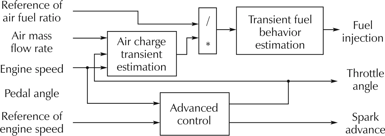
Fig.11 Common architecture of successful controls.
7 Conclusions
The SICE Research Committee on Advanced Powertrain Control Theory provided engine cold start control benchmark problem as the first step of the benchmark problem activities.
Many challengers challenged this problem and they derived control results achieving the goals in various ways. They tried not only the control methods used in the automobile industry but also innovative control methods and unique derivation approaches.They were widely published in academic conferences and journals. The academic societies got concrete knowledge of the problems in the development field.The concrete demonstrations of various methods from academia were shown to the industrial world.It was very effective in filling in the gap between the two parties.
Furthermore, the activities of this benchmark problem continued to two additional benchmark problems at The SICE Research Committee on Advanced Powertrain Control Theory, also to six additional benchmark problems in SICE and JSAE Joint Committee for Automotive Control and Model Research later.These facts mean that this engine cold start control benchmark problem has become the cornerstone of continuous expanding activities.
Acknowledgements
Dr.Zhang,Dr.Jimbo,and other challengers provided many interesting results. Mr. Ohata and Mr. Watanabe supported writing this paper.I would like to express my gratitude for their contributions.
杂志排行
Control Theory and Technology的其它文章
- An overview of various control benchmarks with a focus on automotive control
- JSAE-SICE benchmark problem for vehicle dynamics control
- Revisiting the benchmark problem of starting control of combustion engines
- Control of the common rail pressure in gasoline engines through an extended state observer based MPC
- Introduction to the benchmark challenge on common rail pressure control of gasoline direct injection engines
- Rail pressure controller design of GDI basing on predictive functional control
