Terminal sliding mode control of rail pressure for gasoline direct injection engines
2019-05-08ChenZHANGYingZHANGCongCHAIMiaoleiZHOU
Chen ZHANG, Ying ZHANG, Cong CHAI, Miaolei ZHOU
Department of Control Science and Engineering,Jilin University,Changchun Jilin 130022,China
Abstract The desired fuel rail pressure is a crucial factor for guaranteeing the gasoline direct injection(GDI)engine to work stably.In order to solve the rail pressure control problem,the detailed nonlinear model of GDI is derived and reasonable simplification of this model is carried out for the following controller design.Terminal sliding mode control strategy is proposed to design the rail pressure controller with Lyapunov stability.The designed approach with the fast terminal sliding mode surface makes the system have the capacity of global fast convergence and achieves precise tracking control. To demonstrate the validity of the designed control method, simulations are conducted by tracking the different reference rail pressures. Results show that the designed controller tracks the given reference accurately and has strong robustness.
Keywords: Rail pressure control,terminal sliding mode control,GDI system
1 Introduction
The problem of energy consumption and environmental pollution caused by the increased automobile usage has become a major challenge in recent years[1].To improve the fuel economy and reduce the engine emissions, more and more advanced technologies are applied to modern automobile engines, such as variable geometry turbocharger(VGT)[2],electronic throttle control[3],as well as variable valve timing(VVT)[4].Specifically, gasoline direct injection (GDI) technology shows the great potential in increasing fuel efficiency[5],making the engine work more efficient. However, the pressure fluctuation of common rail system in GDI system can seriously affect the performance of the engine,the rail pressure control is the main sticking point hindering the development of GDI technology.
Scholars have developed some research works on the rail pressure control method for the GDI engine system.The earliest research on modeling and control of rail pressure problem was introduced in diesel engines,then extended to the field of gasoline engines[6].Taking the limitations of traditional PID control into account,a feed forward fuzzy PID controller had been designed in [7]and a mass of comparison experiments between the designed controller and the fuzzy PID controller were made to verify that the suggested method had better performance. Considering the nonlinearity and uncertainty of the system, Liu et al. [8] reported the active disturbance reject control (ADRC), which had a simple structure and the ability of solving the rail pressure tracking problem. Chen proposed a new nonlinear control strategy named triple-step method for rail pressure[9].Compared with the traditional control method,the proposed control method had a simple structure and less time-consuming[10].However,the precision of modeling had influence on the control effect to great extent.To address this problem,D.Gaeta et al.[11]proposed the common rail mean value model and experimentally validated the effectiveness of this model.Moreover,a model reference adaptive control (MRAC) [12] was proposed based on the common rail mean value model and the control method based on the minimal control synthesis algorithm was able to depress the residual pressure in the rail. Another problem is that the structure of the common rail system had a great impact on the design of the controller,hence,the characteristics analysis and optimization of this system were studied in [13,14] to facilitate the design of the controller.
According to[15],the conventional sliding mode control is an effective method to track the rail pressure of GDI system. The design of the sliding mode control is divided into two parts: the design of sliding surface and the design of feedback control law. Z. Man et al. [16-18] indicated that the sliding mode control with a terminal sliding surface exhibits a better performance.Hence,we adopt the terminal sliding surface to describe the dynamic behavior of sliding mode control.The design of feedback control law is using the reaching law, which can attenuate chattering. The terminal sliding mode reaching law can improve the transient performance substantially. In this paper, we firstly adopt the terminal sliding mode control strategy to solve the tracking problem about rail pressure of GDI system.Simulation results show that the designed controller improves the tracking performance to some extent and effectively reduces the fluctuation of the rail pressure.
2 Modeling of common rail system
Common rail fuel injection system is the key component of GDI engine and a simplified model of this system is shown in Fig.1. qtis the fuel amount from the tank to the pressure control valve. The inlet and outlet fuel of the high-pressure pump are expressed as qinand qhc,respectively.qinj_kis the fuel injection amount of the k th injector and qci=qinj_k.qleakis the fuel leakage which can be ignored.
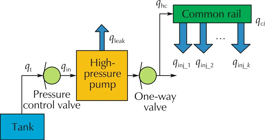
Fig.1 Simplified model of common rail system.
The expression of the common rail system is shown in (1), and the details about the specific derivation and simplifying process can be found in[15].
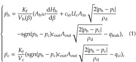
where the pressure and volume of the high-pressure pump are represented by phand Vh,respectively.Similarly, the pressure and volume of the common rail are expressed in terms of pcand Vc. In the inlet and outlet of the pump, cin, coutare the flow coefficients and Ain,Aoutrepresent the cross sectional area. Hhis the instantaneous axial displacement of the piston inside the pump andis a nonlinear function which is related to the camshaft angle β. Ahis the area of piston, ω is the camshaft speed. Ucrepresents the action signal of the pressure control valve.Uc=0 indicates the value is off, while Uc= 1, the value is on. Kfis the modulus of bulk elasticity associating with the ph, but for the sake of controller design,we simplify the Kfas a constant.plis the pressure in the low pressure loop. ρdis the fuel density.The model parameters are given in Table 1.
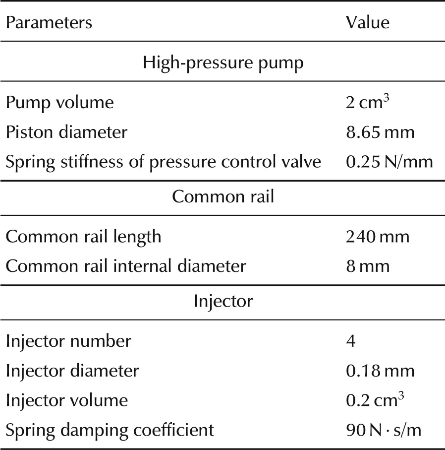
Table 1 Model parameters.
3 Terminal sliding mode control
3.1 Controller design
The terminal sliding mode control is adopted by replacing the traditional linear sliding mode with nonlinear sliding mode, which makes the system state converge to the equilibrium point in finite time,and the dynamic performance of the system is better than sliding mode control.Fig.2 is the structure diagram of proposed controller.Minjis the injection mass.The control objective is that the system output pccan track the reference input pdthrough the adjustment of the designed control approach.According to the explanation of working principle of high-pressure pump in [8] and Fig.1, the inlet fuel of high-pressure pump qincan be controlled by adjusting the closed time (duty cycle) of pressure control valve at the entrance of high-pressure pump, thus changing the system output pressure pc.
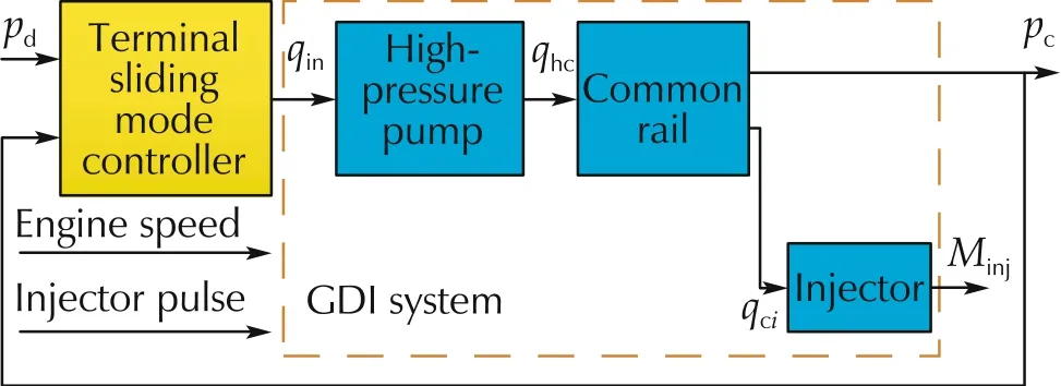
Fig.2 The diagram of proposed controller based on GDI system.
According to (1), x1= phand x2= pcare selected as state variables,and high-pressure pump inlet flow is chosen as control input,that is,

When x1√<x2, the one-way valve makes qhczero.He nce, z =is defined as the new state when x1>x2.The GDI engine system is described as

where
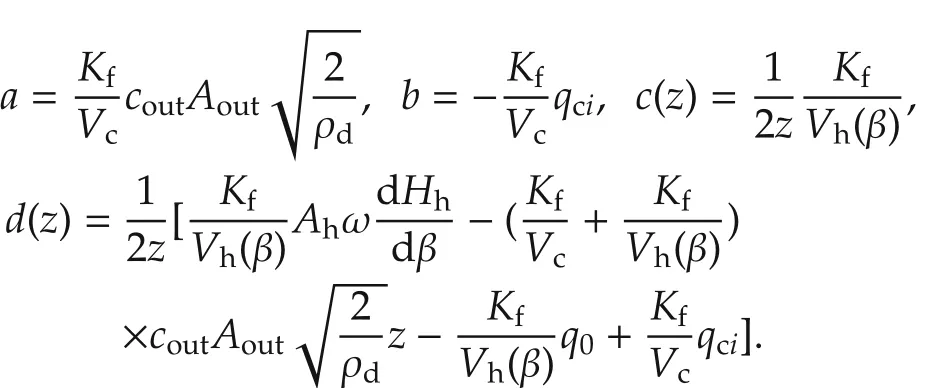
The parameters of (3) is given in Table 1. The control goal of rail pressure is to make the actual rail pressure track the reference rail pressure pdfast,and the rail pressure fluctuation is as small as possible.Set the pressure tracking error as

When x1<x2, for the sake of simplicity, we choose u = 0. When x1>x2, that is the pressure in the highpressure pump is greater than in the common rail.In the paper,we adopt the following terminal sliding surface

where α and λ are positive constants,which are relevant with the controller performance.p and q are positive odd constants.
Reaching law is chosen as

where φ, γ, m and n >0, and m, n are odd. When s is far from zero, s˙=-φs of the reaching law plays a major role in the sliding mode control.When s gradually close to zero,thewhich is called terminal attractor plays an important role in reducing chattering.
Combined(5),(6)with(3),the control law is deduced as follows:

3.2 Stability analysis
With regard to the stability of the designed controller,is selected as Lyapunov function. According to the Lyapunov stability theorem,when(8)is satisfied,the system is in the stability condition.

Substituting(6)and(3)into(8)gains

According to (6), m + n >0, therefore we deduce ˙V <0. Hence, the proposed controller is stable and effective.
4 Simulation results
In this section, to verify the effectiveness of the proposed modeling and control scheme, quantitative simulations are conducted in the environment (MATLAB R2014a) on an Intel(R) Core(TM) i5-4460 CPU 3.20 GHz RAM 4 GB (LENOVO, Beijing, China). The controller parameters α, λ, φ and γ are obtained by the try-and-trial method and finally set as α = 1000,λ = 2,φ = γ = 40000. Given engine speed is 3200 r/min and injection pulse width is 2.2 ms.
In order to verify the tracking performance of the designed controller under the steady-state condition, the step signal is chosen as the reference rail pressure.The tracking and error results are shown in Fig.3(a)and(c).As mentioned above,the control input qinis transformed into an pressure control valve action signal for implementation. That is, the adjustment about qinis realised by changing the valve closed duration(duty cycle).
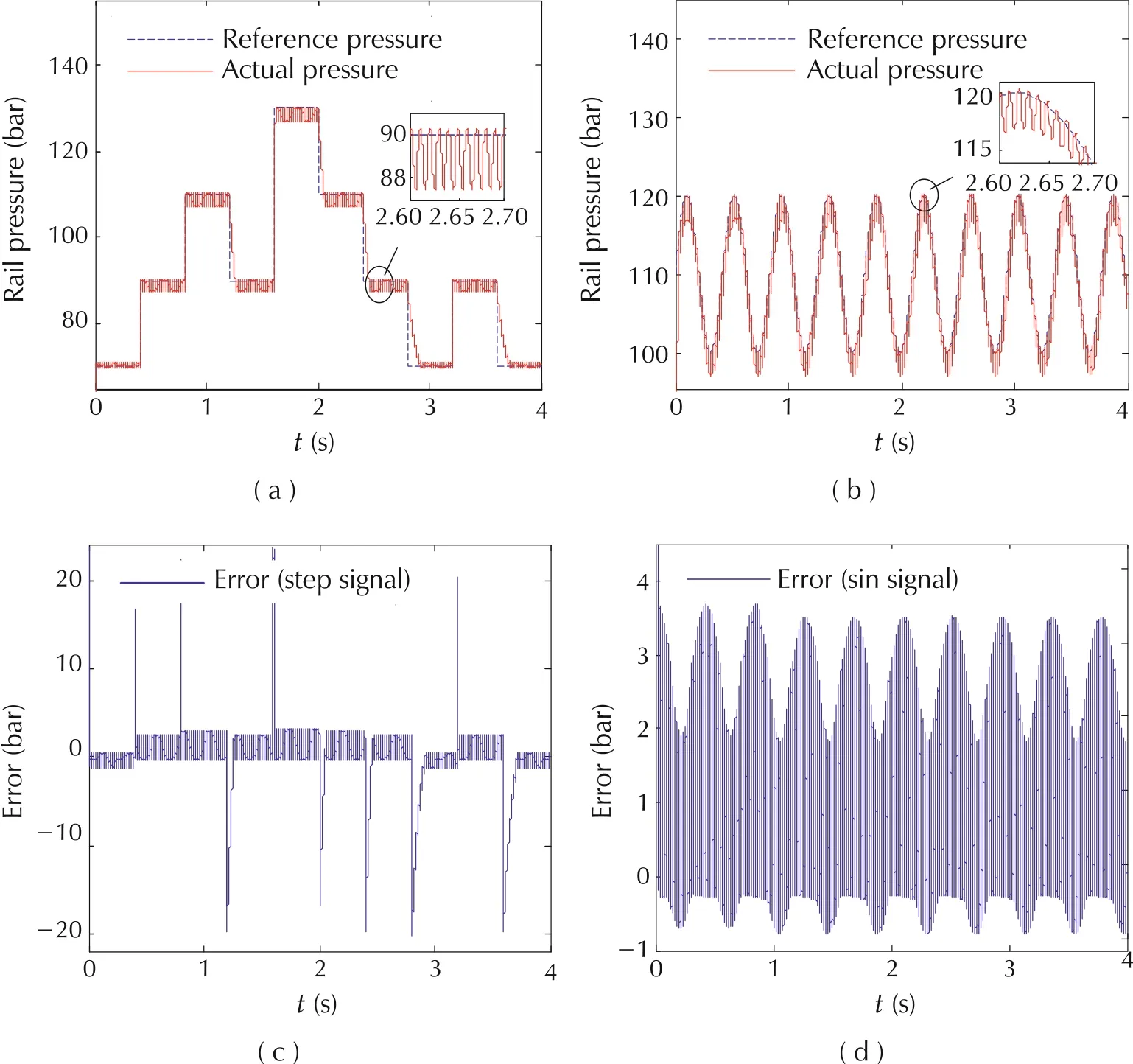
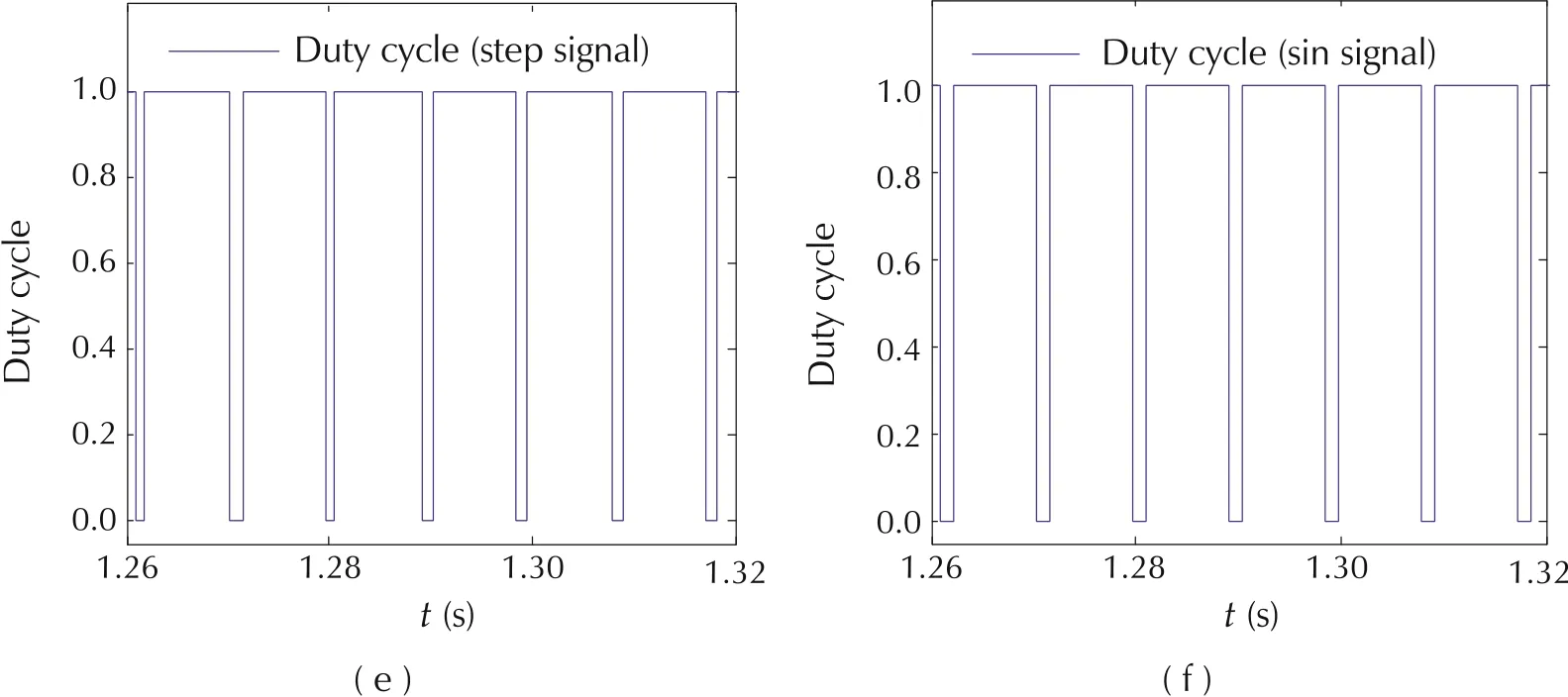
Fig. 3 Rail pressure tracking, error and enlarged duty cycle curves. (a) Step signal tracking curve. (b) Sinusoidal signal tracking curve.(c)Error curve of step signal.(d)Error curve of sinusoidal signal.(e)Enlarged duty cycle curve of step signal.(f)Enlarged duty cycle curve of sinusoidal signal.
Fig.3(e) shows the enlarged duty cycle curve that is the response of the control action qin. It can be seen that the steady-state error is less than 3 bar and the settling time is 100 ms, which means that the designed controller meets the steady-state performance requirement of the common rail system. The sinusoidal signal is applied to valid the dynamic performance of the controller.The average value of this signal is 110 bar and the amplitude is 10 bar.Fig.3(b),(d)and(f)are the tracking curve,error curve of this reference and the enlarged duty cycle curve of pressure control valve corresponding to control law.The tracking error is less than 4 bar,which means the controller still achieve the performance of the common rail system.
To further evidence the tracking capability of the controller,the step signal is adopted as the reference pressure and the range of the pressure is from 70 to 90 bar.The tracking, error and enlarged duty cycle curves under different engine speed and injection pulse width are shown in Fig.4.
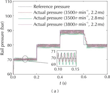
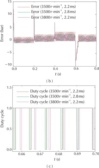
Fig. 4 Comparative tracking, error and enlarged duty cycle curves under different engine speed and injection pulse width.(a) Tracking curves. (b) Error curves. (c) Enlarged duty cycle curves.
As listed in Table 2,when changing the engine speeds and injection pulse widths,the settling time is less than 100 ms and the mean steady-state error is less than 5 bar. The results demonstrate that the proposed controller has strong robustness.
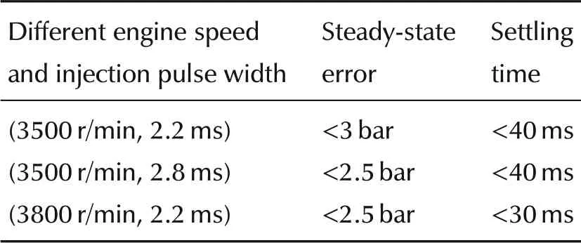
Table 2 Control performance of different work conditions.
5 Conclusions
In this paper, a nonlinear model of the common rail fuel injection system is presented based on the principle of the GDI engine. Terminal sliding mode control method is used to control the common rail pressure,and the stability of this designed system is proved by constructing the Lyapunov function.By tracking the different reference rail pressure signals and analysing the simulation results, the designed controller meets both the steady-state rail pressure control and dynamic rail pressure control requirements of common rail system.
杂志排行
Control Theory and Technology的其它文章
- An overview of various control benchmarks with a focus on automotive control
- JSAE-SICE benchmark problem for vehicle dynamics control
- SICE benchmark problem:starting speed control of SI engines
- Revisiting the benchmark problem of starting control of combustion engines
- Control of the common rail pressure in gasoline engines through an extended state observer based MPC
- Introduction to the benchmark challenge on common rail pressure control of gasoline direct injection engines
