Rail pressure controller design of GDI basing on predictive functional control
2019-05-08ZhimingZHANGLeiXIEHongyeSU
Zhiming ZHANG, Lei XIE, Hongye SU
State Key Laboratory of Industrial Control Technology,Zhejiang University,Hangzhou Zhejiang 310027,China
Abstract Gasoline direct injection (GDI) is a pivotal technique for a highly efficient engine. However, how to maintain a stable rail pressure which offers good fuel economy and low emissions,is still a challengeable work.In this paper,a rail pressure controller is designed basing on predictive functional control(PFC),a model predictive control(MPC)method,to surmount the nonlinearity and discontinuity brought by the common rail pressure system(CRPS).A control-oriented piecewise linear model is presented to simplify the CRPS.The simulation results on a benchmark show that rail pressure tracks the setpoint accurately even with some perturbations. Profiting from the conciseness of PFC algorithm, the controller can compute the online solution in a short time,which makes it possible to realize the strategy on a fast response system.
Keywords: Rail pressure control,model based predictive control,predictive functional control
1 Introduction
Since it was first adopted by Benz 300SL in 1954 to solve the problem of the deficiency of performance in carburetor system,direct injection technique has experienced a downs and ups in the development process.With the increasing demand for fuel economy and environmental protection,together benefitting by technology,in recent decades people have begun to pay attention to GDI technique again[1].For an efficient engine,many parameters need to be controlled,including injection quantity[2],air-fuel ratio[3,4],ignition timing[5],etc.These parameters are directly or indirectly effected by rail pressure[6].Therefore,as the guarantee of GDI technique rail pressure control has become a widely discussed topic in literature and industry.
Common rail pressure system(CRPS)is a typical nonlinear system without enough detection signals. Conventional PID control cannot meet the requirements of being fast and accurate,which is also difficult to tuning.Hence,some nonlinear control methods are considered by researchers.Su et al.proposed a feed forward fuzzy PID controller to prevent the disturbance of injection quantity[7].Triple-step method is introduced to design non-linear controller which looks parameters up in a map in real-time[8].Model based method is also widely employed such as[9].
In this paper the rail pressure is controlled by predictive functional control(PFC)algorithm which belongs to model predictive control (MPC). In MPC, prediction of model in the receding horizon is obtained according to current and past system information, then a finite-time optimal control problem is solved at every time instance,i.e., at every time instance, the controller reformulates a new optimal problem on basis of system information.To simply the problem,a first-order piecewise linear model is used to describe the CRPS. Similar to the approach presented in [8], maps among rail pressure,injection pulse-width and the rev of engine are established to store the parameters of first-order model.The system and control law are implemented in a SIMULINK model,and the test results under different work conditions show the validation of our control scheme.
The rest of paper is organized as follows: CRPS in four-cylinder four-stroke GDI engine and the piecewise linear model are introduced in Section 2. Then in Section 3,predictive control problem with PFC is presented as well as stability analysis with multiple Lyapunov functions[10],which is followed by simulation results on the benchmark in Section 4. Finally, some conclusions and future works are given in Section 5.
2 Common rail pressure system and piecewise linear model
A structure of CRPS is shown in Fig.1,which is composed of a pressure control valve,a high pressure pump(HPP),a fuel rail,four injectors,a fuel rail pressure sensor and the electronic control unit(ECU).The aim of rail pressure controller is to control the pressure in fuel rail by adjusting the pressure control valve’s closed time.To give a mathematical description,the system is modeled on the basis of three parts:HPP,fuel rail,injectors.Symbols used and corresponding physical meanings are listed in Table 1.
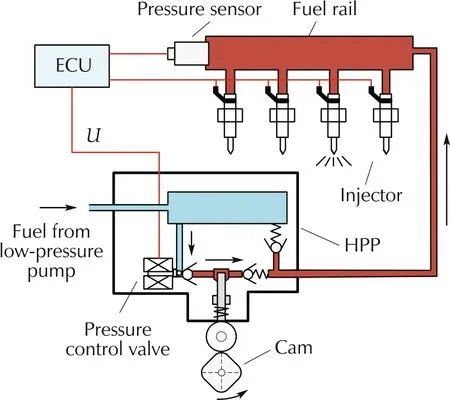
Fig.1 Structure of common rail pressure system.
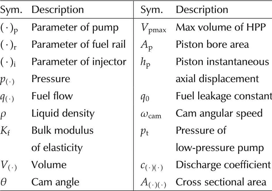
Table 1 Notation.
2.1 High pressure pump
Ignoring the effect of temperature on pressure and volume,HPP pressure is denoted as

where the volume and its derivative are given by


The inlet fuel flow quand the flow from HPP to rail qprare computed by respectively. U is the control signal which represents the state of pressure control valve,i.e.,U=1 if valve is open, U = 0 if valve is close. Hence, pressure control valve’s closed time can be regarded as the generalized input of the CRPS,which is defined as the duty ratio in a work period.The work period is denoted by

where neis the rev of engine.And ne=ωcam,i.e.,no matter how fast is the rev of engine,the cam will rotate by 90 degrees in one work period and there are four periods in one cycle of cam. Note that during pressure control valve’s open time,fuel in Fig.1 flows from lowpressure pump to HPP and only when pressure control valve is closed,fuel in HPP can be pushed into fuel rail.
2.2 Fuel rail
The pressure in fuel rail pris given by

Since qriis the summation of flows in four injectors,every outlet flow is denoted as

where k=1,2,3,4.
2.3 Injectors
The pressure in a injector is mainly influenced by the flow in and out the injector, so similar to equation (5),pikis described as

where k=1,2,3,4,ETkdepends on the injection pulsewidth.The injection pulse-width is the time of opening a injector in one work period T in equation(4),so ETk=1 if it is in injection pulse-width,otherwise ETk=0.
Restricted by the length, please refer to [8] for more details,which is also the origin of the benchmark problem we attended. Then a piecewise first-order linear model is introduced.
It is found that in the sense of trend the step response of CRPS is analogous to a first-order process.However, considering the nonlinear and complex dynamics,a piecewise first-order model is established,i.e.,the parameters in first-order model varies according to working conditions.

Totally N models are used in our method. In other words,the gain and time constant depend on rail pressure, injection pulse-width and the rev of engine. By testing in the SIMULINK model, maps (see Fig.2) are obtained on a basis of a serious of combination of rail pressure,injection pulse-width and rev of engine.
From Fig.2, we can see that gain changes obviously while time constant is almost constant, which is an intuitive result for a first-order-like system.
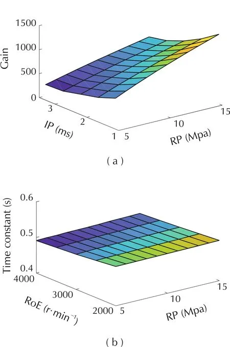
Fig. 2 Ki and Ti under different rail pressure (RP), injection pulse-width(IP),rev of engine(RoE).
3 PFC based controller design
In PFC[11,12],at time instance k the future input of model from 0 to P is assumed to consist of a set of basis functions:

where fn(i) = in-1is the basis function like step, ramp and parabola.μnis the corresponding amplitude of basis function and needs to be solved. Then for a first-order linear model Ym= G(U), the output of model is obtained by

Assumed that at time instant k, the setpoint changes from present state yp(k)to a constant ys,the reference trajectory in the future is denoted by

where Tsis the sampling period,which equals the work period in equation(4)and Tris the desired closed-loop response time.
Given the reference trajectory yr, in PFC, only the outputs on coincidence points are considered in the objective function:

where M is the number of coincidence points.e(k+h)is a feedback compensation calculated on basis of previous model and process output, i.e., e(k+h) = φ,,h),such as Smith prediction. For simplicity, φ(,,h) =yp(k)-ym(k)is adopted in the implementation.
Since we suppose CRPS is a first-order system,given by equation (8), a control law is obtained by using two coincidence points and two basis functions(M=2 and N =2).

where g1and g2is the response of model when input is step and ramp respectively, am= e-Ts/Ti. Tsis the sampling time.
At the end of this section, we give the introduction of implementation and stability analysis of our method by multiple Lyapunov functions.Assuming CRPS can be described by equation(8).At a initial state, y0,one can get a switching sequence like

which describes the trajectory of system xS(·)by the rule:(ik,tk)means that the system evolves according to
Gik(s) =for tk≤t ≤tk+1. Given Theorem 2.3 in[10],we get following theorem for rail pressure controller.
Theorem 1Suppose we have candidate Lyapunov functions Vi,i=1,2,...,N and model equation(8).Let S denote the set of all switching sequences associated with CRPS.
If for each S ∈S it holds that for all i,Visatisfies that
2)Viis monotonically nonincreasing on the sequence of startpoints of times when piecewise model i is active.
Then we say the rail pressure control system is stable in the sense of Lyapunov.
ProofFirst, we set Vi= J in equation (12) without errors for all i.

Then it holds that Vi(k+1)-Vi(k)=[ym(k+1+h)-ym(k+h)][ym(k+1+h)+ym(k+h)-2yr]≤0 for input u(t)≥0,since it is a first-order model.Therefore,˙Vi(x(t))≤0 is satisfied in the discrete-time.
Meanwhile,when each piecewise linear model is used only once, which means that i1≠i2≠...≠iN, we get Viis monotonically nonincreasing on the set of startpoints of times when piecewise model i is active. In addition, when a piecewise linear model is used more than once, since optimal input is obtained when J = 0,Viis still monotonically nonincreasing.Condition(2)is satisfied.
Remark 1The main result of this theorem is that it is unnecessary to find a Lyapunov function to decrease monotonically in the whole control horizon.Conditional(1) indicates that system ikis stable during [tk,tk+1], while condition (2) guarantees the active system is not divergent in the whole active time.
4 Simulation
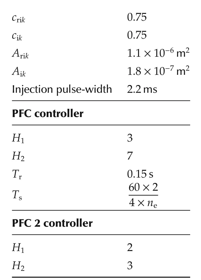
In this section, the PFC based controller is implemented to CRPS in software SIMULINK.The system architecture is shown in Fig.3. Parameters used in PFC controller is collected in Table 2. Three situations are tested: i) step and sine changes of rail pressure setpoint, ii)injection pulse-width disturbance and iii) the rev of engine disturbance.The latter two cases indicate that the system is disturbed.
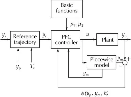
Fig.3 System structure basing on PFC
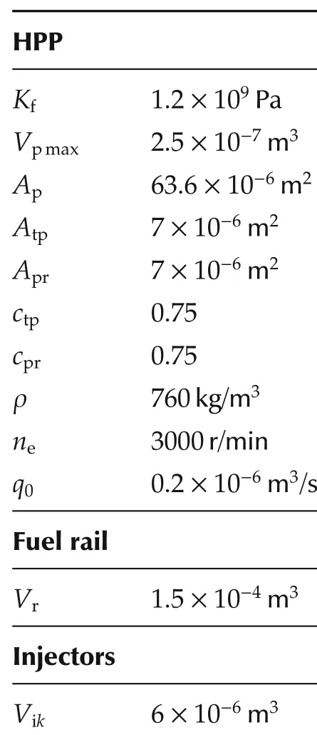
Table 2 Plant and control parameters
In Fig.4(a),reference trajectory changes according to step at the rev of engine 3000 r/min and injection pulsewidth 2.2 ms. Actual rail pressure tracks the reference closely and the settling time is about 50 ms. Then at 0.5 s to 0.6 s, injection pulse-width varies from 2.2 ms to 3.3 ms, leading to a larger rail pressure fluctuation range. At 1.0 s to 1.1 s, the rev of engine changes from 3000 r/min to 4000 r/min which results in a higher frequency of fluctuation.
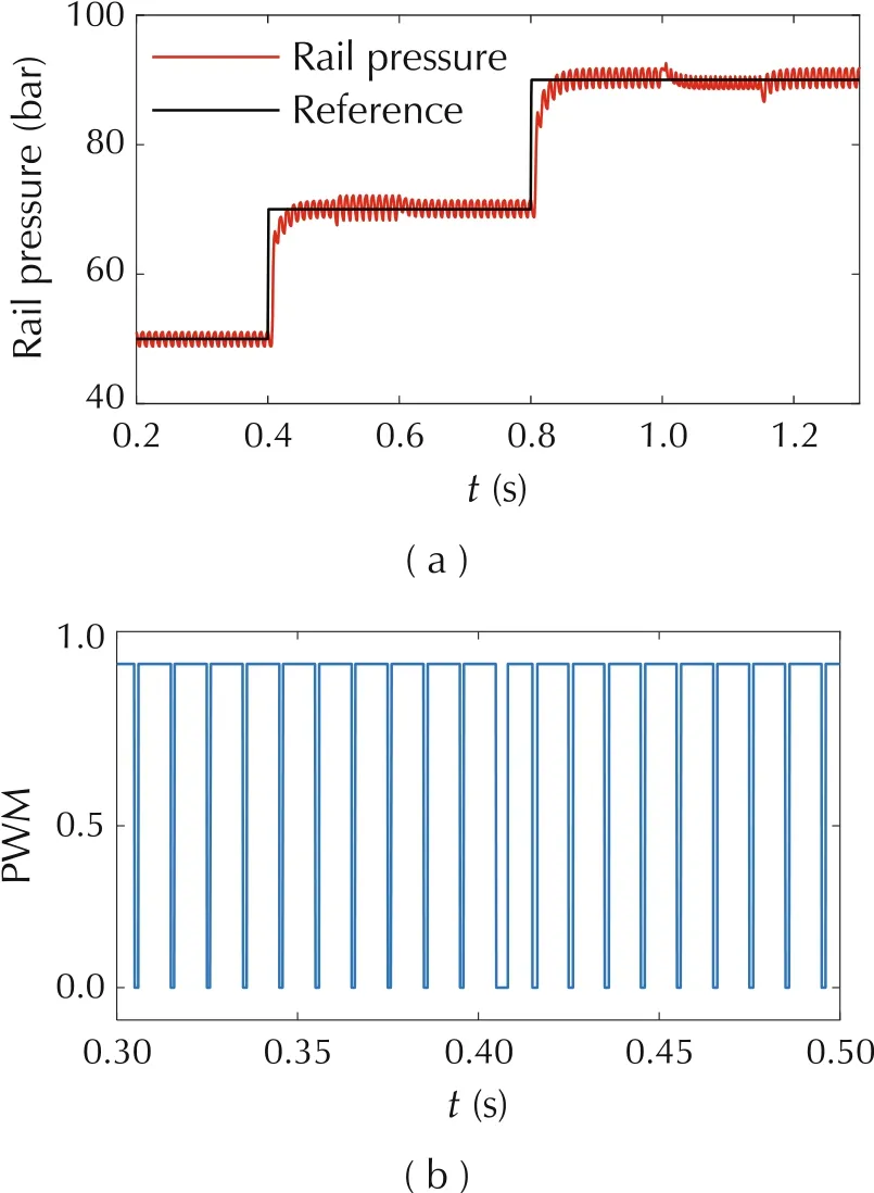
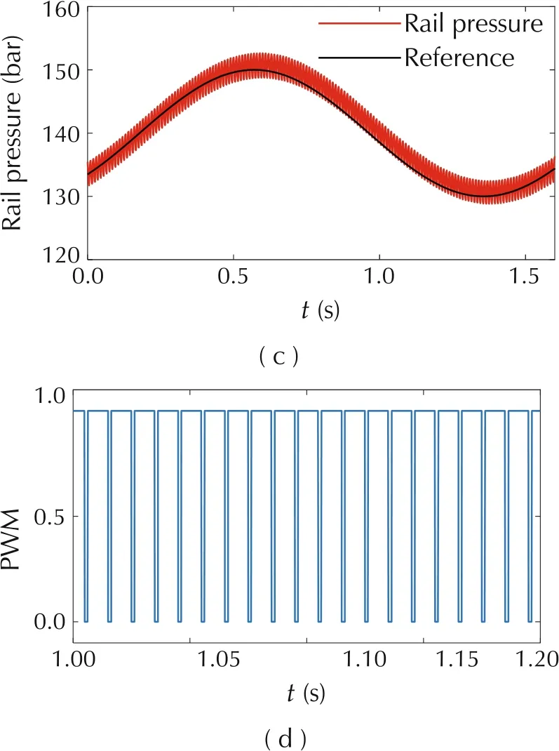
Fig. 4 Test result when reference changes according to step and sine.
In Fig.4(c), rail pressure can also track when reference changes according to sine,with very limited error.The PWM signals in(b)and(d)indicate the switch status of pressure control valve respectively.
A comparison between classical PID and PFC under various control parameters is presented in Fig.5. Here the two coincidence points are changed to H1= 2 and H2= 3, which means that model output needs to be equal to reference trajectory more quickly.Consequently,the response time of rail pressure controlled by PFC 2 is much fast than that controlled by PFC.Additionally, compared with the careful-tuned PID controller,PFC controller can track the reference medially while some deviation exists between rail pressure controlled by PID and reference due to the nonlinearity.
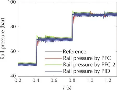
Fig.5 Comparison of different control schemes.
5 Conclusions
In this paper, we have adopted PFC to design a rail pressure controller. In order to overcome the difficulty caused by nonlinearity, a piecewise first-order model has been employed. The simulations under different work conditions prove that the control scheme is effective.
However, the model we assumed is apparently imprecise, which also limits the prediction of controller.Therefore,how to build a more valid model is an important and interesting work.In addition,application in real world system also needs consideration.
杂志排行
Control Theory and Technology的其它文章
- An overview of various control benchmarks with a focus on automotive control
- JSAE-SICE benchmark problem for vehicle dynamics control
- SICE benchmark problem:starting speed control of SI engines
- Revisiting the benchmark problem of starting control of combustion engines
- Control of the common rail pressure in gasoline engines through an extended state observer based MPC
- Introduction to the benchmark challenge on common rail pressure control of gasoline direct injection engines
