基于振动激励溯源的谷物联合收获机清选筛制造缺陷定位
2019-04-26李耀明徐立章周跃鹏
李耀明,庞 靖,2,徐立章,唐 忠,周跃鹏
基于振动激励溯源的谷物联合收获机清选筛制造缺陷定位
李耀明1,庞 靖1,2,徐立章1,唐 忠1,周跃鹏1
(1. 江苏大学现代农业装备与技术教育部重点实验室,镇江 212013;2. 河南科技大学农业装备工程学院,洛阳 471003)
为了识别主要制造缺陷的位置并指导构建往复振动式清选筛质量检测系统,该文提出了一种利用经典传递路径理论反算作用在清选筛与脱粒清选室连接点的激励力,进而定位缺陷位置的方法。通过测量、对比连接点的振动,发现振动频率成分基本相同,且是强相关的,因而不能通过频率分析找出主要激励源而定位制造缺陷。进一步根据激励力与缺陷的关联关系,发现具有最大激励力的激励源附近应存在主要制造缺陷。在测量从连接点到观察点的振动传递函数的基础上,综合广义逆矩阵理论,相位角变化的随机性等,构建了最大激励力和该激励力对观察点振动贡献的计算模型。清选试验台验证测试结果表明,激励力贡献响应之和为实测加速度的84.7%~94.6%,考虑到模型简化时忽略了部分因素的影响,两者基本吻合,计算模型可靠。以键槽间隙为典型缺陷进行验证试验,结果表明,有缺陷时的振动基频和振幅较大的频率对应的激励力比无缺陷时增大71%~3 271%,定位方法有效。
农业机械;振动;模型;清选筛;传递路径;激励力估算;缺陷定位
0 引 言
清选筛作为与风机配合的风筛式清选装置的重要组成部分,广泛应用于各类收获机[1]。由于其传动机构中存在较大的不平衡质量和扭矩,振动强度较大[2-3]。如果零部件的制造缺陷未能及时发现并排除,会使振动更加剧烈,造成立柱开焊,轴承座断裂等严重影响产品可靠性的问题。运转时的振动信号中包含了这些缺陷的特征[4-6],如能通过在线检测振动信号预测缺陷的位置和发生原因,再逐一排查确定缺陷源,替换缺陷件,将明显提升产品可靠性,并能为产品优化设计提供验证手段。
通过检测振动特性即激励源确定缺陷的位置的方法有:偏相干分析法、单源多路径贡献分析法和传递路径分析法[7-8]。偏相干分析法主要应用于主要频率成分存在明显差异的弱相关源[9-10]。单源多路径分析法主要应用于分析单一源通过不同路径对响应影响的排序[11-12]。而传递路径分析法(transfer path analysis-TPA)利用试验测量的振动响应和传递函数,反算出激励力[13-14],对激励源的特异性要求低,能用于强相关源的贡献排序。对于清选筛振动特性的研究,目前国内主要集中于动力学分析[15-16]、激振机构设计与优化[17-18]、惯性力平衡[19-20]、模态分析与共振利用[21-22]等方面。国外多集中于参数共振清选筛的动力学建模[23-25]以指导结构设计。但通过检测分析振动信号识别并定位制造缺陷的研究,未见相关报到。
本文主要通过测量振动响应估算激励力,在建立清选筛结构与动力学模型的基础上,利用传递路径分析理论,计算属于强相关的清选筛与机架连接点的激励力,并根据振动响应的不稳定性,提出利用幅值最大值估算激励力的方法,避免了相位角的影响。
1 清选筛振动传递路径模型
1.1 结构模型
清选筛的驱动机构常采用曲柄摇杆式、曲柄双滑块式和偏心轮滑块式。本文以现阶段履带式全喂入谷物收获机应用较多的偏心轮滑块式为例进行相关研究。偏心轮可简化为短曲柄,其结构简图如图1。
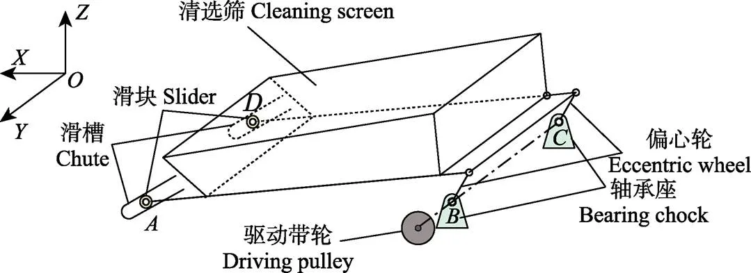
注:A、B、C、D分别表示左滑槽、左轴承座、右轴承座、右滑槽处的结构连接点。
为便于说明,以收割机驾驶员座位前向为轴正向建立三维笛卡尔坐标系。清选筛由带轮驱动,通过、两处的偏心轮(曲柄)带动整个筛体运动,筛体前方通过2个滚动轴承嵌入机架侧壁的滑槽内。由图1可以看出,清选筛的振动激励由结构连接点(、、、)向机体传递。
1.2 动力学模型
相对于清选筛,驱动带轮的质量较小,可以忽略。将筛子看作左右对称结构,筛体正常安装时向位移远小于其他2个方向,为简化计算,忽略方向的振动,假定筛体只在平面内做平面运动,建立清选筛的动力学模型,如图2所示。清选筛受到的力包括质心处的重力/2和惯性力,处滑块受到的力包括重力mg惯性力ma和支撑力R,处偏心轮受到的力包括重力mg惯性力ma和支撑力R,还有通过驱动轴传来的转速为的扭矩。可以看出,通过、两点作用于机体的支反力的4个分力R、、、即为清选筛作用于机架的振动激励源。

注:M为清选筛的质心,E为偏心轮与清选筛的铰接点。RAX、RAZ、RBX、RBZ分别为各点X向和Z向支反力,N;mAaA、ma、mEaE分别为滑块、清选筛和偏心轮的惯性力,N;mAg、mg、mEg分别为滑块、清选筛和偏心轮的重力,N;q为滑槽与水平面夹角,rad;w为角频率,rad·s–1;F为驱动轴转矩,N·m。
根据文献[19],清选筛的惯性力随结构参数和质量而变化,但均呈与驱动轴旋转同周期的近似简谐规律,其角频率为
=2π2π60 (1)
式中为旋转频率,Hz;为驱动轴和偏心轮的转速,r/min。
根据达朗贝尔原理,支反力与各部件的重力和惯性力平衡。各重力为恒定值,则支反力也应与惯性力一样呈近似简谐特性。
1.3 振动传递路径模型
为了分析清选筛对收获机机体振动的影响,建立如图3的振动传递模型。作用于、两处的各向支反力会引起机架上任意点的振动响应,将所有激励力引起的响应求和即为点的加速度a。根据图2对清选筛的受力分析,不失一般性,清选筛的激励力R、R、R、R可表示为R(=1,2,3,4)。根据线性叠加原理和传递路径分析理论[26]有:

式中h(t)表示从R的施力点到点的传递函数,*表示卷积。(这里只考虑振动,忽略声音的影响)。写成频域形式为
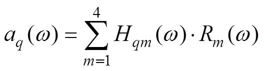
式中H()表示频响函数。通过计算激励力R()和该激励力对任意点在特定频率0处的振动贡献H()·R()|0,并与无缺陷时的贡献进行比较,如存在较大差异即可确定R的施力点就是存在缺陷的位置,应对其附近的零部件进行排查。而频率0就是缺陷的特征频率。

注:q为机架上的任意点;Hqm为频响函数,m·s–2×N–1; aq为q点的响应加速度,m·s–2。
1.4 激励力计算
式(3)中H()通过力锤激励法测量。a()为加速度响应的傅立叶变换(频谱),也可通过试验获取。但激励力R()(=1,2,3,4)如果用力传感器直接测量,需要将传感器安装在清选室机架与滑槽、轴承座之间,会改变结构形式,不仅不便于在线检测,而且改变了激励力,影响测量准确性。因此工程上常采用求解方程的方法反算出激励力。为求解方程,需计算连接点处的3向加速度,即
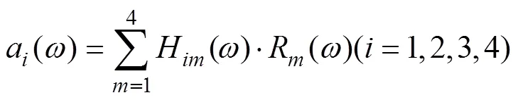
式(4)与式(3)组合,写成矩阵形式,即

由于系统的频响函数是系统的固有属性,不随环境和激励的变化而变化。如存在逆矩阵[()]-1,将其左乘式(5)有:

根据1.2节的简化,激励力只有4个,理论上只需测量连接点和的向和向4个激励力到机架上任意4个测点的4×4阶频响函数矩阵[()]4×4即可。但由于结构的相似性,矩阵元素的值可能十分接近,矩阵成为病态矩阵无法求逆。为使方程可解,根据文献[27],增加响应点数量,使响应点加速度变为[()]8×1,频响矩阵取8行,变成[()]8×4,通过求解其广义逆[()]+4×8,即可得到激励力:

1.5 激励相位角
由于式(3)中的函数均为复数,在求和计算加速度响应a()时,需要考虑相位角。
将各复数写成复指数形式,公式(3)变为
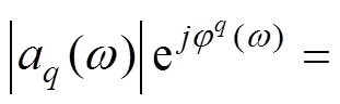

合并相位角

式中|a()|、|H()|、|R()|表示各函数的模,φ()、φ()、φ()表示相位角,(°)。
显然,各激励力引起的响应相位角φ()+φ()(=1,2,3,4)不完全相同,所以响应和的幅值小于等于各激励引起的响应幅值的和,即
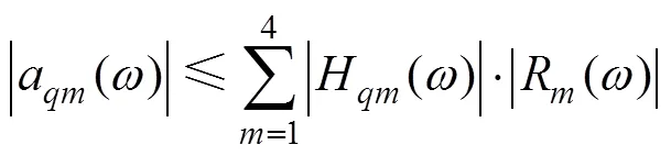
2 清选筛振动特性测量
2.1 测量方法
试验于2018年6月至8月在江苏大学农业装备工程学院南大间实验室的智能型清选系统试验台架上进行。为了在测试时不引入其他运动部件的影响,只启动清选筛驱动电机而不启动其他电机,研究清选筛单独振动时机体的响应特性。使用3向加速度计获取清选筛与机架连接点和机架上观察点的3向加速度,使用力锤激励法获取结构的传递函数。试验场景和测点位置见图4,试验设备技术参数如表1。考虑到测量对象的运动频率较低,试验的采样频率为2 560 Hz。
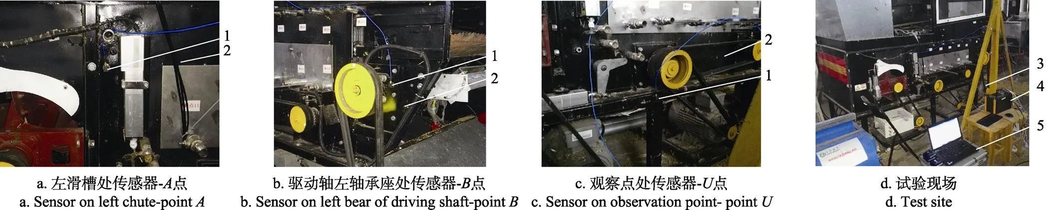
1. 3向加速度计 2. 机架 3. 驱动电机 4. 动态信号采集仪 5. 电脑
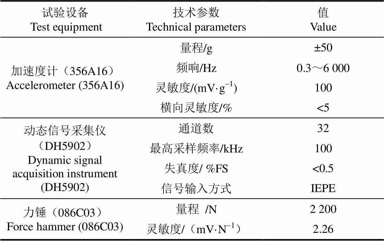
表1 振动测试试验设备
2.2 信号时频域分析
设置清选筛驱动转速为正常工作转速即340 r/min,测量连接点、的向和向加速度。为分析振动响应以获取载荷的动态特性,对2个连接点处2个方向的时域信号进行短时傅立叶变换(short time fourier transform,STFT)[28-30]。
由于转动频率只有5.65 Hz,对于结构振动来说,对同样幅值的加速度信号积分求其振动位移时需乘以系数1/2,角频率越大,则位移越小,对结构的变形影响越小。因此本文分析只计算到100 Hz,忽略高频部分,计算结果如图5所示。分析图5可知,振动信号的频率成分较多,除了驱动转速基频外,还有各次倍频。、连接点处的频率成分基本相同,对其进行相关性计算,常相干系数大多在0.9以上,属于强相关。8 s后进入工作状态,各点各方向的频率成分没有变化,但频率幅值随时间有明显变化。连接点、的向低频部分,在10~25 Hz的3个倍频的幅值比其他倍频大,在向75~90 Hz的高频段幅值达到最大,点各频率的幅值均大于点。通过时频域特性可知,实际振动并不具有理论分析的简谐特性,而是表现为多频率成分且不稳定。这大多是由零部件制造缺陷造成的[4,31],累积后会降低清选筛和整机的可靠性,减少设备预期寿命,甚至存在安全隐患。因此有必要通过测量、分析振动信号,找出制造缺陷。
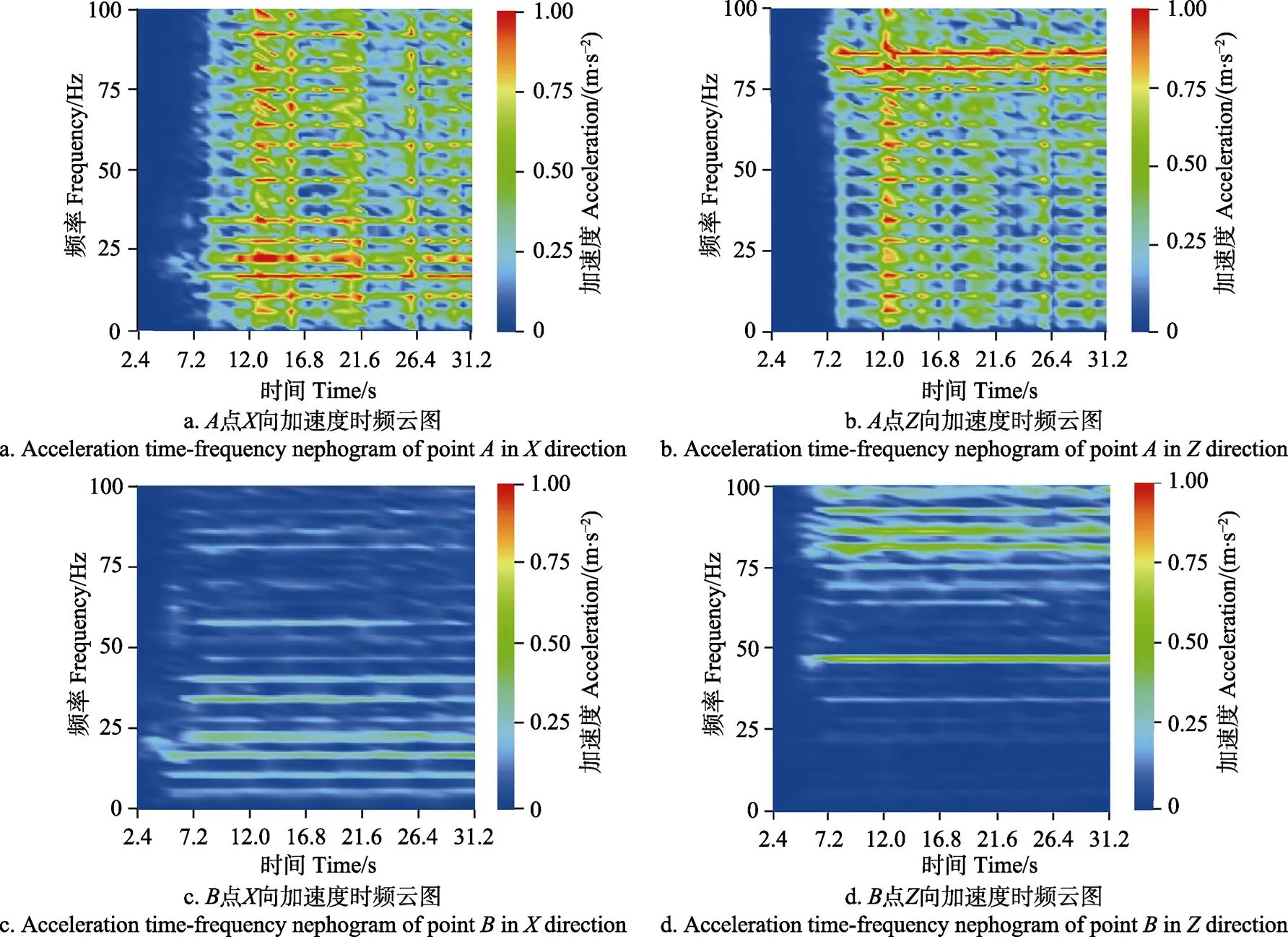
图5 清选筛与机架连接点的加速度时频云图
2.3 频响函数测量
根据1.4节,分析激励力并进行缺陷定位需要测量频响函数H(),检测设备见表1,频响函数采用1估计[32],利用模态力锤分别沿向和向激励连接点和,测量4种激励条件下的脉冲响应。为计算H()的广义逆,需要增加测量点数量,因而在试验支架右侧与点对称的位置设置另一观察点。测量和点各3个方向及、点向在4种激励条件下,共计32种脉冲响应,经傅立叶变换计算出频响函数,得到传递函数矩阵[()]8×4。计算过程中,分析谱线数为1 600,频率分辨率0.625 Hz,重叠率50%,计算平均谱。点向激励时,、点的向和点3向的跨点频响函数曲线,以及到点的3向原点频响函数曲线如图6所示。
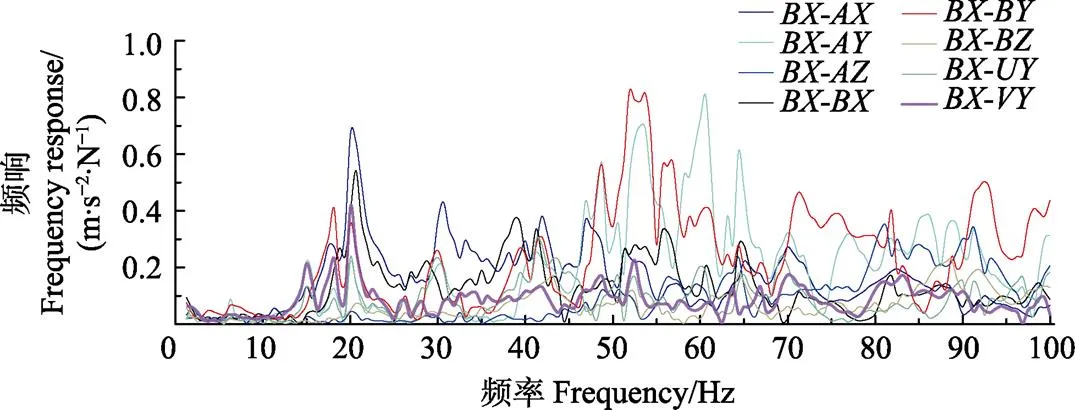
注:BX-AX表示用A点X向的加速度响应除以B点X向激励力得到的频响函数,其他类同。
2.4 相位角测量
频响函数H()反映系统的固有特性,其相位角φ()理论上应是固定值,不随激励和环境变化。如果激励力R()的相位角φ()也是不变的,则激励响应和的相位角φ()也应是固定值。为了验证上述假设,分别计算试验台架稳定运转时连接点、的振动响应,观察点、的向响应相位谱。点向和点向在14、20 和29 s的相位谱如图7所示。

图7 不同时刻加速度响应相位谱
由图7可知,各点的相位角在不同时刻是不同的。这说明激励力的相位角φ()并不是不变的,其可能原因是:由于装配间隙、接触件摩擦、轴心不对正等问题,清选筛的运转并不平稳,实际的支反力受到这些因素的影响而发生一定程度的随机变化;清选室在清选筛的激励下发生振动,特别是侧板的向振动使清选物质量在空间的分布发生一定变化,从而造成连接点到观察点的频响函数也发生变化。而且频响函数的相位角对本体的质量分布变换比较敏感,变化较大。
激励力和频响函数的相位角都是变化的,所以由它们组合决定的振动响应和的相位角也是变化的。考虑到这些变化具有随机性,当4个激励力引起的响应同方向时,加速度可取得最大值,即

式(11)说明激励力引起的振动响应可由观察点处的振幅极大值表示,也说明如果某个清选筛部件存在制造缺陷,测试时由缺陷造成的激励力会使某些特征频率的振幅最大值明显增大。
3 缺陷定位
应用传递路径模型的激励力计算法,可以根据清选筛单独运转时观察点的加速度响应,和激励力作用点(连接点)到观察点的频响函数计算出作用在连接点的激励力幅值,进而根据幅值是否超过正常加工状态的激励力判断出清选筛在该连接处附近的结构是否存在制造缺陷。在收获机的设计试制阶段,通过计算样机的激励载荷对振动响应的贡献|H()|·|R()|并对其排序。依照贡献大小顺序,对引发响应较剧烈的激励力进行分析并采取对应的防护或改进措施,可有效降低机体的振动,提高产品的可靠性和使用寿命。
3.1 激励力辨识
振动响应的相位角不稳定,激励力辨识不再适用式(3),而应使用由式(11)推导的激励力幅值式(12)计算。
[|()|]=[|()|]+• [|()|max] (12)
式中广义逆[|()|]+可由[|8×4()|]的奇异值分解计算得出,[|()|]由最小二乘法优化算出。
3.2 响应幅值及激励源的贡献
根据图5的频谱图,100 Hz内的各阶倍频是主要的激励频率。这里以点向的基频和加速度较大的3个倍频为例,计算激励力和激励贡献(加速度)响应,结果如表2。由表2可知,计算得到的激励力贡献响应和为实际测量加速度的84.7%~94.6%,考虑到模型简化时忽略了部分因素,计算值和实测值基本吻合,模型计算结果可信。激励力3的幅值和贡献较大,即点处前后向的振动贡献大,这也与试验中发现的驱动轴处振动剧烈相符,因此处向是主要激励源。

表2 不同频率下激励力和激励贡献响应计算结果
注:1、2、3、4分别代表点向、点向、点向、点向的支反力。下同。
Note:1,2,3and4represent the support reactions of pointindirection, pointindirection, pointindirection and pointindirection respectively. The same below.
3.3 驱动轴键间隙缺陷验证
为了验证本文提出的基于振动响应估算激励力的缺陷识别方法,以常见的清选筛驱动链轮与驱动轴间的键槽间隙为例进行试验验证。将原本略有过盈的平键磨削至与键槽有0.2 mm间隙,测量此时的加速度响应,并进行STFT变换,画出时频云图,如图8。
将图8与图5对比可以看出:虽然振动响应的频率成分没有明显变化,但点基频和主要频率处的振幅都有明显增大(驱动轴键槽靠近点,点可以反映缺陷附近的振动情况)。与表2对比点(点为任意观察点,具有普遍性)的振动也明显增大。为了确认这样的响应变化是由哪些激励力引起的,将基频5.625 Hz和表2中的3个特征频率40.625、86.875和92.5 Hz以及图8c中23.125 Hz对应的最大振幅带入式(11),计算各频率激励力的幅值,结果如表3。
对比表2和表3中的振动加速度,除40.625 Hz外,其余各频率处都是增加的,且增加明显。对比激励力的幅值,点处各频点激励力的幅值在存在键槽间隙缺陷时增加了8%~48%;点处的激励力幅值增加了71%~3 271%,增幅巨大,说明主要缺陷应该在点附近,处只是受的影响或故障不大,证明利用振动传递路径模型对清选筛进行制造缺陷定位的方法有效。
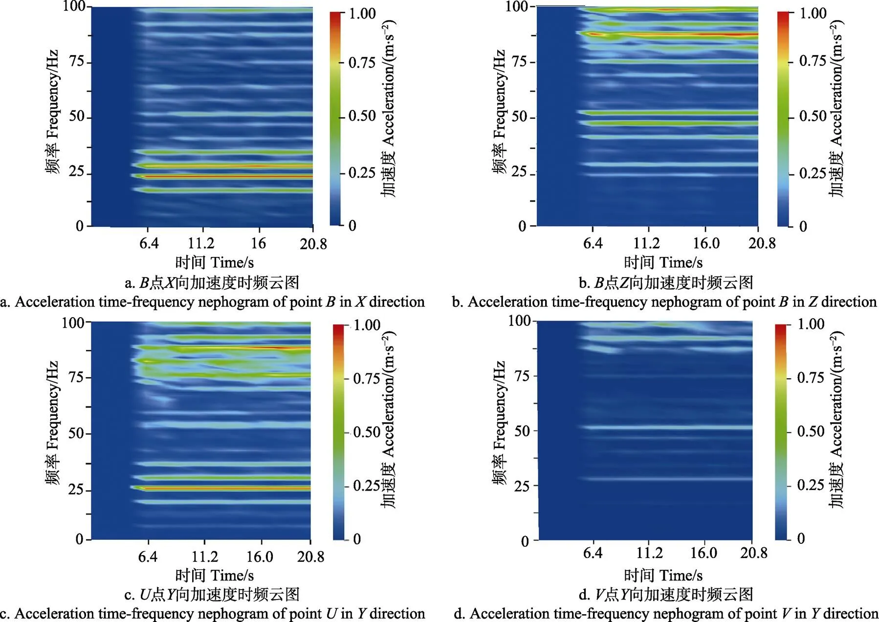
图8 验证试验测点加速度时频云图
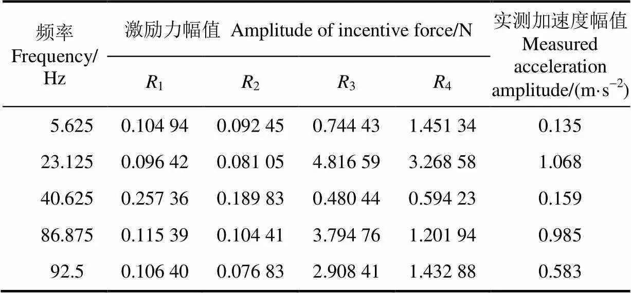
表3 激励力验证试验结果
4 结 论
1)清选筛由于往复运动产生的振动主要通过滑槽和驱动轴轴承座向脱粒清选室传递,而且这2处的振动频率成分基本相同,属于强相关激励源。因此可采用经典传递路径分析理论,通过分析振动特性确定装配缺陷的可能位置。
2)清选筛作业时激励力和振动响应都会发生变化,因此无法利用振动的相位信息计算激励力,而应依据统计原理,以幅值最大值为计算依据,估算各频率处的激励力幅值。
3)通过在清选试验台上测量正常工作时根据模型计算的理论振动响应与实测振动响应对比,发现理论计算值比实测响应略有减小(为实测值的84.7%~94.6%);键槽有间隙时的激励力计算值与无间隙时相比,有缺陷时的激励力幅值在其基频和振幅较大的频率处都有明显增大(71%~3 271%),本文方法有效,可定性地为制造缺陷定位提供指导。
为了简化分析计算过程,文中忽略了筛体向振动对机架振动的影响,实际上应考虑4个连接点处各3个方向共计12个激励力对机架振动的激励,计算过程难度增大,但流程和结果与文中相同。对振动测量点相位变化的原因文中给出了初步判断,但具体原因和消除其变化的方法还需进一步研究。本文只根据异常激励力辨别给出缺陷的位置确定方法,缺陷是哪种类型,如何克服还需要进一步研究。
[1] 张敏,金诚谦,梁苏宁,等. 风筛选式油菜联合收割机清选机构参数优化与试验[J]. 农业工程学报,2015,31(24):8-15. Zhang Min, Jin Chengqian, Liang Suning, el al. Parameter optimization and experiment on air-screencleaning device of rapeseed combine harvester[J]. Transactionsof the Chinese Society of Agricultural Engineering (Transactions of the CSAE), 2015, 31(24): 8-15. (in Chinese with English abstract)
[2] 徐立章,李耀明,孙朋朋,等. 履带式全喂入水稻联合收获机振动测试与分析[J]. 农业工程学报,2014,30(8): 49-55. Xu Lizhang, Li Yaoming, Sun Pengpeng, el al. Vibration measurement and analysis of tracked-whole feeding rice combine harvester[J]. Transactions of the Chinese Society of Agricultural Engineering (Transactions of the CSAE), 2014, 30(8): 49-55. (in Chinese with English abstract)
[3] 高志朋,徐立章,李耀明,等. 履带式稻麦联合收获机田间收获工况下振动测试与分析[J]. 农业工程学报,2017,33(20):48-55. Gao Zhipeng, Xu Lizhang, Li Yaoming, el al. Vibration measure and analysis of crawler-type rice and wheat combine harvester in field harvesting condition[J]. Transactions of the Chinese Society of Agricultural Engineering (Transactions of the CSAE), 2017, 33(20): 48-55. (in Chinese with English abstract)
[4] Firla M, Li Z Y, Martin N, et al. Automatic characteristic frequency association and all-sideband demodulation for the detection of a bearing fault[J]. Mechanical Systems & Signal Processing, 2016(80): 335-348.
[5] Xiao Y, Enjie D, Chunxu C, et al. A novel characteristic frequency bands extraction method for automatic bearing fault diagnosis based on Hilbert Huang transform[J]. Sensors, 2015, 15(11): 27869-27893.
[6] 李凌均,陈超,韩捷,等. 全矢支持向量回归频谱预测方法[J]. 郑州大学学报:工学版,2016,37(3):78-82. Li Lingjun, Chen Chao, Han Jie, et al. The prediction method of frequency spectrum based on full vector support vector regression[J]. Journal of Zhengzhou University: Engineering Science, 2016, 37(3): 78-82. (in Chinese with English abstract)
[7] Zafeiropoulos N, Moorhouse A, Mackay A, et al. A comparison of two in-situ transfer path analysis methods [C]//RASD 2013 11th International Conference on Recent Advances in Structural Dynamics. DOI:http://dx.doi.org/
[8] De Klerk D, Ossipov A. Operational transfer path analysis Theory, guidelines and tire noise application[J]. Mechanical Systems and Signal Processing, 2010, 24(7): 1950-1962.
[9] 谢小平,曹远龙,王茜影,等. 基于总贡献系数和的客车噪声源识别[J]. 汽车工程,2017,39(5):575-580,587. Xie Xiaoping, Cao Yuanlong, Wang Xiying, et al. Identification of bus noise source based on total contribution coefficient sum[J]. Automotive Engineering, 2017, 39(5): 575-580, 587. (in Chinese with English abstract)
[10] Huang H B, Huang X R, Yang M L, et al. Identification of vehicle interior noise sources based on wavelet transform and partial coherence analysis[J]. Mechanical Systems and Signal Processing, 2018(109): 247-267.
[11] 赵薇,周娜,张义民. 振动传递路径系统的路径插入损失分析[J]. 东北大学学报:自然科学版,2015,36(2): 250-253,258. Zhao Wei, Zhou Na, Zhang Yimin. Path insertion loss analysis of vibration transfer path systems[J]. Journal of Northeastern University: Natural Science, 2015, 36(2): 250-253, 258. (in Chinese with English abstract)
[12] 张义民. 频域内振动传递路径的传递度排序[J]. 自然科学进展,2007,17(3):410-414.
[13] 侯锁军,史文库,毛阳. 应用传递路径分析方法对方向盘抖动贡献量的研究[J]. 西安交通大学学报,2013,47(3):132-136. Hou Suojun, Shi Wenku, Mao Yang. Vehicle steering wheel wobbling contribution investigation by transfer path analysis[J]. Journal of Xian Jiaotong University, 2013, 47(3): 132-136. (in Chinese with English abstract)
[14] 曹跃云,张磊,杨自春,等. 船舶振动噪声源传递路径分析及试验验证[J]. 振动与冲击,2013,32(22):158-162. Cao Yueyun, Zhang Lei, Yang Zichun, et al. A new OPA model for ship noise sources and test validation[J]. Journal of Vibration & Shock, 2013, 32(22): 158-162. (in Chinese with English abstract)
[15] 王中营,任宁,武文斌,等. TQLZ型往复振动筛动力学模型与虚拟样机仿真[J]. 食品与机械,2016,32(2):67-70. Wang Zhongying, Ren Ning, Wu Wenbin, et al. Dynamic model and virtual prototype simulation of TQLZ type reciprocating vibration screen[J]. Food & Machinery, 2016, 32(2): 67-70. (in Chinese with English abstract)
[16] 汪建新,郑小伟. 基于Workbench的直线振动筛运动学和动力学分析以及结构改进[J]. 机械强度,2014,36(6): 846-849.Wang Jianxin, Zheng Xiaowei. Kinematics, dynamics analysis and structure improvement of linear vibrating screen based on workbench[J]. Journal of Mechanical Strength, 2014, 36(6): 846-849. (in Chinese with English abstract)
[17] 李扬扬,贺朝霞,宋绪丁,等. 沥青搅拌设备振动筛系统动力学分析及其参数影响研究[J]. 计算力学学报,2015,32(4):565-570. Li Yangyang, He Zhaoxia, Song Xuding, et al. Dynamic analysis and influence study of structure parameters on the asphalt mixing plant vibration screen system[J]. Chinese Journal of Computational Mechanics, 2015, 32(4): 565-570. (in Chinese with English abstract)
[18] 卫良保,赵广洋,杨莎莎,等. 振动筛偏心块的优化设计及动力学仿真[J]. 煤矿机械,2014,35(10):258-260. Wei Liangbao, Zhao Guangyang, Yang Shasha, et al. Dynamic simulation of optimized eccentric block of vibrating screen[J]. Coal Mine Machinery, 2014, 35(10): 258-260. (in Chinese with English abstract)
[19] 李革,王婵,李颖聪,等. 曲柄滑块式清选筛机构惯性力平衡研究[J]. 农机化研究,2016,38(8):24-30, 35. Li Ge, Wang Chan, Li Yingcong, et al. Investigation on inertial force balancing of slider-crank type cleaning sieve[J]. Journal of Agricultural Mechanization Research, 2016, 38(8): 24-30, 35. (in Chinese with English abstract)
[20] 洪美琴. 联合收割机脱粒系统中振动筛的动力学分析[J]. 农机化研究,2012,34(5):79-82. Hong Meiqin. The dynamics analysis of vibrating sieve in threshing system of combine harvester[J]. Journal of Agricultural Mechanization Research, 2012, 35(5): 79-82. (in Chinese with English abstract)
[21] 方守艳,胡继云,孙庆春. 双振动体惯性往复反共振振动筛的动力学分析[J]. 河南工业大学学报:自然科学版,2013,34(6):56-59. Fang Shouyan, Hu Jiyun, Sun Qingchun. Dynamics analysis of inertial reciprocating anti-resonant vibration screen with two vibration bodies[J]. Journal of Henan University of Technology: Natural Science Edition, 2013, 34(6): 56-59. (in Chinese with English abstract)
[22] 杨俊哲. 基于Workbench多倾角型振动筛的模态分析[J]. 煤炭学报,2012,37(S1):240-244. Yang Junzhe. Modal analysis for multi-angle vibrating screen based on ANSYS workbench[J]. Journal of the China Coal Society, 2012, 37(S1): 240-244. (in Chinese with English abstract)
[23] Slepyan L I, Slepyan V I. Coupled mode parametric resonance in a vibrating screen model[J]. Mechanical Systems and Signal Processing, 2014, 43(1): 295-304.
[24] Zahedi S A, Babitsky V. Modeling of autoresonant control of a parametrically excited screen machine[J]. Journal of Sound and Vibration, 2016, 380: 78-89.
[25] Slepyan L I, Slepyan V I. Modeling of parametrically excited vibrating screen[J]. Journal of Physics: Conference Series. IOP Publishing, 2013, 451(1), Article id: 012026(2013). DOI: 10.1088/1742-6596/451/1/012026
[26] M V van der Seijs, D de Klerk, D J Rixen. General framework for transfer path analysis: History, theory and classification of techniques[J]. Mechanical Systems & Signal Processing, 2016(68/69): 217-244.
[27] D de Klerk, Ossipov A. Operational transfer path analysis: Theory, guidelines and tire noise application[J]. Mechanical Systems and Signal Processing, 2010, 24(7): 1950-1962.
[28] Griffin D, Lim J. Signal estimation from modified short-time Fourier transform[J]. IEEE Transactions on Acoustics, Speech, and Signal Processing, 1984, 32(2): 236-243.
[29] Aubel C, Stotz D, Bölcskei H. A theory of super-resolution from short-time Fourier transform measurements[J]. Journal of Fourier Analysis and Applications, 2018, 24(1): 45-107.
[30] 杜巧连,张克华. 基于自身振动信号的液压泵状态监测及故障诊断[J]. 农业工程学报,2007,23(4):120-123. Du Qiaolian, Zhang Kehua. Condition monitoring and fault diagnosis of hydraulic pump based on inherent vibration signals[J]. Transactions of the Chinese Society of AgriculturalEngineering (Transactions of the CSAE), 2007, 23(4): 120-123. (in Chinese with English abstract)
[31] 郑坤明,张秋菊. 含关节间隙的Delta机器人弹性动力学与振动特性分析[J]. 农业工程学报,2015,31(14):39-48. Zheng Kunming, Zhang Qiuju. Elastic dynamics and analysis of vibration characteristics of Delta robot with joint clearance[J]. Transactions of the Chinese Society of Agricultural Engineering (Transactions of the CSAE), 2015, 31(14): 39-48. (in Chinese with English abstract)
[32] 傅志方,华宏星. 模态分析理论与应用[M]. 上海:上海交通大学出版社,2000.
Manufacturing defect location of cleaning screen of grain combine harvester based on vibration excitation tracing
Li Yaoming1, Pang Jing1,2, Xu Lizhang1, Tang Zhong1, Zhou Yuepeng1
(1.212013,; 2.471003,)
In order to improve the processing quality and reliability of the cleaning screen of grain combine harvester, it is necessary to eliminate the manufacturing defects in the design and pilot stage, which causing the additional load, , and to locate and eliminate the processing defects by measuring in the production stage. In this paper, a method can locate and calculate the exciting forces act on the connection points of cleaning screen and thresher body by classical transfer path analysis (TPA) were developed. By measuring and comparing the vibrations of the connection points, it is found that the vibration frequency components were the same and were strongly correlated, so it is impossible to find the main excitation source by analyzing the frequency to locate the manufacturing defects. According to the relationship between exciting force and defect, it is pointed out that there should be major manufacturing defects near the maximum excitation force. The vibration of connection points and a certain observation point of the test bench were measured by using triaxial accelerometers and dynamic signal analyzer , and the characteristics of time domain and time-frequency domain were analyzed. The results showed that although there was no change in the frequency components in the spectrum, the amplitude changed greatly, and the phase changed greatly at different times of each frequencies. The transfer functions of the connection points to each measurement points were detected by using a modal force hammer and vibration measuring devices. Since the phase was unstable, according to the principle that the product of each excitation force and the transfer function (ie, the contribution of the excitation force to the vibration) had the largest vibration response in the same direction, the maximum acceleration amplitude was introduced into the inverse matrix method formula, and the influence of the phase was ignored, and the problem that the ill-conditioned matrix of the transfer function matrix could not be inverted was solved by increasing the measurement point, the generalized inverse matrix of transfer function was calculated by singular value decomposition. The calculated excitation force was optimized by least squares method, and finally the practical incentive calculation formula was derived. In order to verify the validity of the method, the magnitude of the excitation force during normal operation and the contribution to the vibration indirection of the observation point were calculated. The results showed that the sum of contributions was only slightly smaller than the measured acceleration, which was about 84.7%-94.6% of the measured value, the excitation force calculated by this method was basically correct. The keyway clearance was used as a typical defect for the location verification test. It was found that the amplitude of each frequency in the excitation force spectrum near the defect increased significantly (71%-3 271%), while the amplitude of the slot excitation force away from the defect was only slightly added, the effectiveness of the positioning method was verified. The defect localization method proposed in this paper only adds one accelerometer and one measuring instrument to the original cleaning screening assembly quality inspection platform, the vibration excitation force at the connection points between the cleaning screen and the rack mounting could also be roughly calculated by measuring 4-8 acceleration responses.
agricultural machinery; vibration; models; cleaning screen; transmission path; incentives force estimation; defect location
2018-09-10
2019-01-07
国家重点研发计划项目(2017YFD0700203)
李耀明,博士,教授,博士生导师,主要从事农业装备关键技术的基础理论及产品的开发研究工作。Email:ymli@ujs.edu.cn
10.11975/j.issn.1002-6819.2019.05.002
S225.3;TB533+.1
A
1002-6819(2019)-05-0010-08
李耀明,庞 靖,徐立章,唐 忠,周跃鹏. 基于振动激励溯源的谷物联合收获机清选筛制造缺陷定位[J]. 农业工程学报,2019,35(5):10-17. doi:10.11975/j.issn.1002-6819.2019.05.002 http://www.tcsae.org
Li Yaoming, Pang Jing, Xu Lizhang, Tang Zhong, Zhou Yuepeng. Manufacturing defect location of cleaning screen of grain combine harvester based on vibration excitation tracing[J]. Transactions of the Chinese Society of Agricultural Engineering (Transactions of the CSAE), 2019, 35(5): 10-17. (in Chinese with English abstract) doi:10.11975/j.issn.1002-6819.2019.05.002 http://www.tcsae.org
