Lesson Eighty-eight How to perform permanentHis bundle pacing in routine clinical practice
2019-04-10童鸿
Clinical permanent His bundle pacing(PHBP)was first described in 2000.Since then,several investigators acrossthe world have published the safety and feasibility of PHBP.Benefits include ability to achieve physiological pacing by recruiting the native His Purkinje system and avoiding electrical dyssynchrony,potentially translating into reduced HF incidence.Also,limited clinical observations have demonstrated that the lead does not cross the tricuspid valve and this may result in lower incidence of valvular regurgitation.
Equipment requirements
Following are the equipment requirements:
1.Medtronic(Minneapolis,MN)383069-cm His lead with 1.8-mm exposed helix,lead outer diameter(OD)4.2F(Figure 1A).It is a solid core pacing lead with no central lumen to deliver a stylet,requiring a long sheath for delivery.
2.Medtronic C315 His nondeflectable sheath(43cm),inner diameter(ID) 5.5F,OD 7.0F(see asterisk in Figure1B),primary curve to reach the superior aspect of the tricuspid annulus,secondary curve to reach the septum.A Medtronic deflectable sheath (C304-69;ID5.7F and OD 8.4F) is also available with unidirectional deflection(Figure1C);it can be helpful in challenging anatomical situations(dilated right atrium[RA] ,an inferiorly displaced His bundle[HB] ,etc.).
3.Short 7F peel-away sheath to place the C315 His sheath through it.It allows continued vascular access after the His sheath is split(guide wire can be retained as well).
4.Pace-sense analyzer(PSA)to record intracardiac electrograms(EGMs).Because of the inherent sensing algorithms built into the Medtronic PSA,we usually connect the pacing lead to the atrial channel(higher gain setting of 0.05 mV/mm).For PSAs of other manufacturers,the lead can be connected to the ventricular channel.
5.Unipolar connection to map the HB EGMs with the pacing lead.We use the pacing lead to map the HB with PSA EGMs,without the need for a mapping catheter.Also,an electrophysiology(EP) recording system can be used(PSA EGMs are adequate).
6.Twelve-lead electrocardiogram for the procedure(critical to analyze pacing morphologies to confirm recruitment of the HB).

Figure 1 A:Select Secure 3830 lead.B:Several nondeflectable sheaths used for the 3830 lead.The first sheath marked by the asterisk is a C315 His nondeflectable sheath used for His bundle mapping and lead placement.All other sheaths are used for either right atrialor rightventricular lead placement.C:Deflectable sheath used occasionally to place the His bundle lead
Procedure description
Once vascular access is obtained(cephalic,axillary,or subclavian vein),a guidewire is advanced into the RA or RV.A short 7F sheath can be advanced over the wire to retain access.Otherwise,the C315 His sheath is advanced into the RA or RV and the guidewire removed.The pacing lead is advanced to the tip of the sheath,with the distal tip of the lead exposed minimally.Unipolar connections are made with the tip of the lead and cardiac tissue.
If the sheath and the lead tip are in the RV,the apparatus is gently pulled back to the atrioventricular grove with minimal counterclockwise rotation to ensure that the lead tip is abutting the septum.If the sheath and the lead are in the RA,gentle forward clockwise rotation tends to move the apparatus to the summit of the tricuspid annulus.
While this is being performed,it is important for both the operator and the person operating the PSA to pay careful attention to intracardiac EGMs.Small movements are encouraged as HB deflections can be easily missed.We usually set the sweep speed to 50 or 100 mm/s to allow better separation of atrial,HB,and local ventricular EGMs.
Once HB EGMs are obtained,unipolar pacing is performed since the proximal pole of the lead is within the sheath.We start pacing at 5 V@1 ms and assess 12-lead QRS morphologies.The following patterns can be observed:
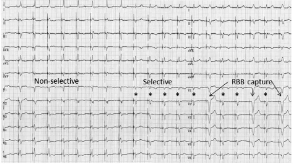
1.Pure HB pacing where stimulus to ventricular activation is equal to the intrinsic HV interval and paced QRS morphology is identical to the intrinsic QRS complex.We term this as selective HB pacing(Figure 2,Figure 3).
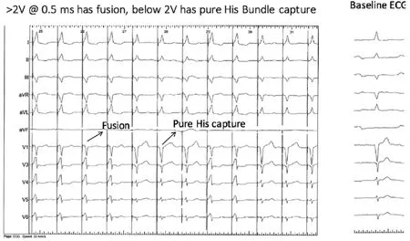
2.HB capture with local ventricular fusion:stimulus-ventricular capture is shorter than the HV interval.The pacing output is decremented to assess the changing QRS morphologies(akin to para-His pacing performed to assess septal accessory pathways).We term this as nonselective HB pacing(Figure 2,Figure 3).Various responses can be observed:
(a)At high output,the HB is preferentially recruited with progressive widening as output is reduced,resulting in more local ventricular capture.
(b)At high output,more fusion is encountered because of local ventricular capture,and at lower output,HB is preferentially activated,resulting in less fusion(Figure 2,Figure 3).
(c)Sometimes just before loss of capture,pure HB pacing can be seen.Also,selective RBB or left bundle branch(LBB)capture can be demonstrated(Figure 3).
(d)Sometimes because of the proximity of RBB and more ventricular placement of the lead,RBB capture can occur.This results in an LBB block pattern-wide QRS complex.It may be difficult to determine whether local myocardial capture occurs along with RBB capture.If intrinsic conduction is present,measuring the HV interval can help determine RBB capture.Typically,a local HV interval would be short(<30 ms),with no far-field atrial EGM seen on the PSA.
We believe that these responses are due to anatomical and functional aspects of the HB system.Anatomy of the HB has been well characterized.Preferential pacing of RBB and LBB can be explained in part by the phenomenon of longitudinal dissociation of the His-Purkinje conduction system.Other properties such as favorable source-sink1ratios and virtual electrode polarization may play a part as well.
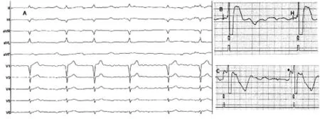
Once HB capture is ascertained,the lead is turned 4-5 times in a clockwise direction.Usually,torque is built up and transmitted to the end of the lead.Once it is released,the lead may unwind 1-2 rotations.It is important to use the sheath to support the lead and make good contact with the septum.The sheath is pulled back,and the lead is advanced to allow for slack.Current of injury,either of the HB or local ventricular tissue,is usually seen(Figure 4).However,there are cases where the lead is well affixed with good pacing thresholds and minimal local tissue injury.Testing is performed in both unipolar and bipolar configurations.Starting at 5V@1 ms,output is decremented to assess response to pacing.Either selective or nonselective HB pacing is accepted,and pacing thresholds less than 2V@1 ms are deemed acceptable.If the patient is pacemaker dependent,lower pacing thresholds are sought after before accepting the final lead position.If the pacing threshold margins are not deemed acceptable by the operator after multiple attempts,the lead is placed slightly more anteriorly,with largerventricularsensingand pacingmorphology consistent with septal pacing.

Figure 2 At pacing outputs above 2V@0.5ms,there is fusion with His bundle(HB)and local ventricular capture(nonselective HB capture).Below 2V@0.5ms,there is pure HB capture with paced QRS morphology identical to the native QRS complex(selective HB pacing).Note that once pure His capture is obtained as the pacing threshold,inter-mittent fusion is still high enough to intermittently recruit the local venticular myocardium.ECG=electrocardiogram.

Figure 3 At higher output(up to 1.5V@1 ms),there is fusion between His bundle and local myocardial capture(nonselective response).At lower outputs(up to 0.5 V@1ms),there is pure His bundle capture with stimulus to QRS onset(S-QRS)equal to the native HV interval(selective response,*).Below this output,there is selective right bundle branch(RBB)capture.

Figure 4 A:Ten-lead electrocardiogram of a 74-year-old man with permanent AF,incomplete left bundle branch block pattern,and bradycardia.B:Pace-sense analyzer electrograms as the His bundle is mapped in a unipolar configuration (connected to the atrial channel).C:Current of injury of the His bundle as the lead is screwed into place.Asterisk denotes current of injury of the His bundle as the lead is screwed into place.
Acute ventricular sensing issues
Because of the location of the lead tip,we see a wide range of ventricular sensing values(1.2-10 mV).We compare ventricular EGMs with atrial EGMs to assess sensing margins.Typically,the lead tip records small atrial EGMs and atrial oversensing is not a major issue.Unipolar and bipolar sensing is assessed,and if no far-field sensing is seen,unipolar sensing can be used if it offers better sensing safety margins.However,it is rare that we program unipolar ventricular sensing.In patients who are pacemaker dependent,we do not use unipolar sensing and ventricular sensitivity is usually set to>1.2 mV on the basis of measured values and care is taken to assess far-field atrial sensing before accepting the final location of the ventricular lead.
Acute pacing issues
The HB is encased in a fibrous sheath with various anatomical variations.Pacing thresholds are expected to be inherently higherbecause ofthe lead-tissue interface.Therefore,if pacing thresholds are lower than 2V@1 ms at implantation with good HB recruitment,we accept the lead position.Typically,as the pacing output decreases,there is more fusion with ventricular capture,thereby providing good safety margins(nonselective HB pacing cases only).The pacing output is set to 5V@1 ms at implantation and decreased at
2-month check.In dependent patients,we look for at least 2-3 times safety margin.We aim for nonselective HB pacing in such cases and determine safety margins from the lowest output capture of either the HB or local ventricular tissue.If selective HB pacing is desired in the setting of higher pacing thresholds,we place a backup lead in the RV.This necessitates placement of a BiV pacemaker with the HB lead plugged into the LV port.We program an LV to RV offset of 80 ms.If HB capture occurs,the RV stimulus falls in the refractory period,resulting in functional noncapture.If HB capture does not occur,the RV stimulus acts as safety pacing.
词 汇
recruit n.&v.新兵、心成员、新手;招募、组织、雇佣
dyssynchrony n.非同时、非同步、非共时性
helix n.螺旋、耳轮
unidirectional adj.单向的
inherent adj.内在的
algorithms adj.算法
grove n.沟、树丛、果树林
abut v.邻接、与 邻接,与 紧靠
intrinsic adj.固有的、内部的、内在的
decrement n.&v.减少、减量、减缩两;减少,减缩
akin adj.同类的、同族的、同源的
torque n.&v.扭转力、金属饰环、转距;加转距于
slack n.&adj.&adv.&v.松弛、萧条;松弛的、懈怠的、松闲
的;松弛地、松闲地;放松、懈怠、减缓
affix n.&v.附加物、词缀;黏上、盖、添上
deem n.&v.评价;认为、认为 是
margin n.&v.边缘、边、利润额、余地;加边于
encase v.把 装入箱子、围住、包装
offset n.&adj.&v.补偿、支管;补偿的、错断的、胶印的;补
偿、把 并列
注 释
1.source-sink(ratio)指“源 -库(比)”,最初用于描述生物物种的迁移现象。心脏电生理学上用source-sink来阐述一些心脏传现象,在此,source-sink指的是电流负荷(current-load),传导系统局部的容量变化可加快或减慢激动传导速度。When the source volume is larger compared with the sink volume,activation proceeds because there is sufficient electrical current to activate myocardial cells in the distal direction.当源容量大于库容量时激动进展,因有足够的电流激动远端心肌细胞。Local source-sink relationships determine the formation of conduction heterogeneities and provide conditions for the development of slow conduction,unidirectional block,and reentry.局部源-库关系决定传导异质性并提供发生慢传导、单向阻滞和折返的条件。
参考译文
第88课 临床实践中如何实施希氏束起搏
2000年首次提出希氏束起搏,自那以后,国际上多位研究者发表了希氏束起搏的安全性和可行性的报道。希氏束起搏的优点在于通过自身的希氏束系统达到生理性起搏,避免电不同步,从而减少心力衰竭的发生率。另外,有限的临床观察证实电极不跨过三尖瓣,三尖瓣反流的发生率较低。
设备要求
1.美敦力(Minneapolis,M)383069-cm 希氏束电极,突出的螺旋1.8-mm,电极外径(OD)4.2F(图1A)是一无实心起搏电极,无内腔供定型钢丝通过,而需长鞘输送。
2.美敦力C315希氏束非可调弯鞘(43cm),内径(ID)5.5F,OD 7.0F(见图1B星标),第一弯到达三尖瓣环上方,第二弯到达间隔。美敦力可调弯鞘(C304-69;ID 5.7F和OD 8.4F)可做单向偏弯(图1C);有助于挑战性的解剖情况[扩大的右心房,下移的希氏束等] 。
3.短7F撕开鞘用于输送C315希氏束鞘。它使得希氏束鞘撕开后保持血管通路(也可保留指引导丝)。
4.起搏-感知分析仪(PSA)用于记录腔内电图(EGMs)。鉴于整合到PSA中的内在感知算法,我们通常将起搏电极连接到心房通道(设置较高的增益,0.05mV/mm)。对于其他厂商的PSAs,电极可连接到心室通道。
5.电极连接起搏电极标测希氏束EGMs。我们用起搏电极标测希氏束和PSA EGMs,无需标测电极。也可用电生理(EP)记录系统(PSA EGMs足够的)。
6.手术过程需12导联心电图(对于分析起搏图形确定夺获希氏束至关重要)。
手术过程阐述
一旦建立血管通路(头静脉、腋静脉、锁骨下静脉),指引导丝送入至心房或心室。短7F鞘沿导丝送入以保留通路,或者送入C315希氏束鞘到心房或心室而拔出指引导丝。起搏电极送入至鞘的顶端,尽可能少的露出电极远端。电极顶端与心脏组织采用单极连接。
如鞘和电极顶端位于右心室内,轻轻回撤器械到房室沟,略作逆种向旋转以保证电极顶端紧密接触间隔。如鞘和电极位于右心房内,轻轻顺种向推送器械到三尖瓣环的最高点。
在这一操作过程,术者和PSA操作者都应注意腔内电图。建议小幅移动,因为希氏束波易被遗漏。我们通常设置屏扫速度为50或100mm/s,以便分开心房、希氏束和局部心室EGMs。
一旦获得希氏束EGMs,实施单极起搏,因为电极的近端电极位于鞘内。我们以5V@1ms开始起搏并分析12导联QRS波群。可以观察到以下类型:
1.纯希氏束起搏时起搏信号到心室激动的间期与自身的HV间期相同,起搏的QRS形态与自身的QRS形态一致。我们称这种起搏为选择性希氏束起搏(图2-3)。
2.希氏束夺获融合局部心室激动:起搏信号-心室夺获间期短于自身HV间期。降低起搏输出来分析QRS形态变化(类似实施希氏束旁起搏分析间隔旁路)。我们称其为非选择性起搏(图2-3)。可以观察到不同的反应:
(a)高输出下,希氏束优先被激动并随输出减少而进行性增宽,导致较明显的局部心室夺获。
(b)高输出下,因为局部心室的夺获而呈明显融合,低输出下,希氏束优先激动,以致融合少。(图2-3)。
(c)有时在丧失夺获前可见到纯希氏束起搏。也可见到选择性RBB或LBB夺获(图3)。
(d)有时因为电极更接近RBB和心室,可发生RBB夺获。这导致LBB阻滞的宽QRS波群。这难以确定局部心室夺获时是否伴随RBB夺获。如存在自身的传导,测定HV间期有助于确定RBB夺获。典型的表现是局部HV缩短(<30ms)而PSA上无远场心房EGMs。
我们相信这些反应与希氏束系统的解剖和功能有关。希氏束的解剖特征明确。优先起搏RBB和LBB可用希氏束-普肯氏传导系统的纵向分离现象加以部分解释。其他特性如正向源-库比和虚拟电极极化也可起到部分作用。
一旦确定希氏束夺获,电极顺钟向旋转4~5圈。通常情况下扭力会传递到电极末端。一旦松开,电极会回转1~2圈。重要的是利用鞘支撑电极并紧密接触间隔。回撤鞘管,同时推送电极使其呈松弛状态。通常可见到希氏束或局部心室组织的损伤电流(图4)。然而,有时电极固定好且起搏阈值理想但局部组织损伤微小。在单极和双极情况下测试。起始为5V@1ms,降低输出来分析对起搏的反应。选择性或非选择性起搏是可接受的,起搏阈值低于2V@1 ms认为是可行的。如患者是起搏依赖的,在接受最好的电极位置前应寻求更低的起搏阈值。如经过术者多次努力,起搏阈值不能被接受,应将起搏电极略前移,有较大的心室感知和起搏图形,与间隔起搏相一致。
急性心室感知问题
鉴于电极端的位置不同,我们见到宽泛的心室感知值(1.2~10mV)。我们比较心室的EGMs和心房的EGMs分析感知临界值。典型的是电极端记录到小的心房EGMs和心房过感知不成为一个大的问题。分析单极和双极感知,如无远场感知且能提供良好的感知安全范围,可选用单极感知。然而,我们极少设置单极心室感知。对于起搏器依赖者,我们不选用单极感知,根据测定的基础值,心室感知设置通常>1.2mV,在接受最后的心室电极位置前注意分析远场心房感知。
急性起搏问题
希氏束被包绕于纤维鞘中,有着多种多样的解剖变化。因为电极-组织的界面关系,起搏阈值自然较高。因此,植入时如起搏阈值低于2V@1ms时能良好激动希氏束,我们接受电极的位置。典型的是当输出降低时,更多融合心室夺获,因此提供良好的安全界限(仅为非选择性希氏束起搏病例)。植入时将起搏输出设在5V@1ms,两个月随访时降低。对于依赖者,我们寻求2~3倍的安全界限。此类患者我们的目标是非选择性希氏束起搏,从希氏束或局部心室组织确定最低的输出夺获。如需在起搏阈值较高的情况下寻求选择性希氏束起搏,我们在右心室植入备份电极。这使得有必要选择双室起搏器,将希氏束电极插入左心室接口。我们程控左心室向右心室补偿80ms。如希氏束发生夺获,右心室的刺激落在不应期内,导致功能性失夺获。如希氏束无夺获,右心室刺激充当安全起搏。
图1A:选择安全的3830电极。B:几种用于3830电极的非调弯鞘。第一根标记星号的为C315希氏束非调弯鞘,用于希氏束标测和电极放置。所有其他鞘用于右心房或右心室电极放置。C:偶尔用于希氏束电极放置的可调弯鞘。
图2起搏输出2V@0.5ms以上时,出现希氏束与局部心室夺获的融合(非选择性希氏束夺获)。输出低于2V@0.5ms时,纯希氏束夺获的起搏QRS形态与自身QRS波相一致(选择性希氏束起搏)。注意一旦纯希氏束夺获作为起搏阈值,间歇性融合仍然足可间隙地激动局部心肌。ECG=心电图。
图3较高输出下(up to 1.5V@1ms),希氏束与局部心肌夺获之间融合(非选择性反应)。较低输出下(up to 0.5 V@1ms),呈单纯希氏束夺获,起搏信号与QRS波群起始点之间的间期(S-QRS)与自身HV间期一致(选择性反应,*)。低于该输出时,呈选择性RBB夺获。
图4A:74岁男性持续性心房颤动伴不完全性左束支和心动过缓的十导联心电图。B:起搏-感知分析仪电图显示的希氏束标测单极图形(与心房通道连接)。C:电极旋入后的希氏束损伤电流。星号标注电极旋入后的希氏束损伤电流。
