H∞Preview Control for Automatic Carrier Landing
2019-03-07FARHANMasoodXUEYixuanZHENZiyangYANGLiuqing
FARHAN Masood ,XUE Yixuan,ZHEN Ziyang,2*,YANG Liuqing
1.College of Automation Engineering,Nanjing University of Aeronautics and Astronautics,Nanjing 211106,P.R.China;
2.Jiangsu Key Laboratory of Internet of Things and Control Technologies,Nanjing 210016,P.R.China
Abstract:This paper focuses on the application of H∞preview control in automatic carrier landing system(ACLS)for carrier-based aircraft.Due to the mutual movement between aircraft and carrier,the landing process becomes considerably more challenging compared to a conventional runway landing.ACLS systems mitigate this by predicting deck motion and generating ideal glide slope path for tracking.Although,this predicted glide slope information is available in advance,conventional control structures are still unable to use this future information.H∞preview control has the ability to utilize this future information for improving tracking response and disturbance rejection.The process of incorporating preview information into ACLS framework and synthesizing the H∞preview controller is presented.The methodology is verified using the example of F/A-18 automatic carrier landing problem and results are presented.
Key words:H∞control;preview control;carrier-based aircraft;automatic carrier landing;robust preview control
0 Introduction
One of the most demanding tasks facing a pilot is landing of an aircraft on a carrier.The rough ocean environment,a short landing strip,and movement of the carrier make carrier based landing considerably more daunting compared to landing on a stationary ground based runway[1-2].Pitch and heave motion of the carrier,brought about by rough ocean conditions,can dramatically change the touchdown point and cause large vertical deck velocities.This can result in reducing impact velocity margins[3].In most modern aircrafts,low speeds of approach are more prone to unstable,especially in the presence of air-wake disturbances[4-5].The compounded effects of all these factors make the automatic carrier landing a difficult control problem with tight tracking error tolerances[6].Automatic carrier landing system(ACLS)helps ensure the safest approach velocity and descent slope to the carrier deck and touchdown[7].Since the ideal glide slope trajectory is already known and deck motion is predictable to some degree,ACLS becomes an ideal application for preview control[8].Preview control utilizes this future information to greatly enhance transient response[9].
Recently,there has been an increasing interest in preview control[10-19].One of the most popular approaches for synthesizing discrete-time optimal preview controllers is to augment the system with a delay line model and converting the preview control problem to standard H2/H∞control framework[20].A problem with this approach is that the size of associated discrete algebraic Riccati equation(DARE)increases with the increase in preview length.The usual methods of brute force optimization quickly become infeasible with longer preview lengths.This problem has been solved recently forand forH2control methods have been significantly more attractive to engineers in the past due to the difficulties associated with H∞based methods.Therefore most of the theoretical work on H∞based preview control was scattered over numerous publications.A single and generic framework for solving H∞preview control problems was unavailable until recently[23].The main contribution of this paper is to apply the techniques refined and collected for tackling H∞preview control problems,from an engineering point of view,to the ACLS framework.The process of adding preview to a traditional ACLS control problem and synthesis of controller using standard H∞control theory[24]is discussed.Finally,the methodology is verified using the example of F/A-18 automatic carrier landing problem.
1 Problem Statement
Although H∞preview control has considerable scope for application given the superior performance and robustness properties,the work is mostly theoretical in nature and there is a need to produce a generic set of tools for application in flight control.The aim of this work is to provide a set of practical solutions for application of H∞preview control to flight control by using the example of ACLS.Furthermore,the procedure of adding preview to a standard ACLS framework and converting the resulting preview control problem into standard H∞framework as given in Green&Limebeer[24],needs to be laid out in an application friendly manner.
2 H∞Preview Control Scheme
2.1 Generalized plant model
Consider the following generalized linear discrete plant model(Fig.1),as Green&Limebeer[24]

where x(k)∈Rngis the state vector,u(k)∈Rmthe control input,z(k)∈Rpthe cost output,and y(k)∈Rqgthe measurement output of the system.Moreover,r(k)∈Rlrdenotes the previewable exogenous signal which can be considered as reference signal or the disturbance.Let the preview length be N,i.e.the values of r(k),r(k+1),…,r(k+N)are available for the controller.
The objective is to synthesize a controller K=[Ky′Kr′]′which generates the control input as[20]
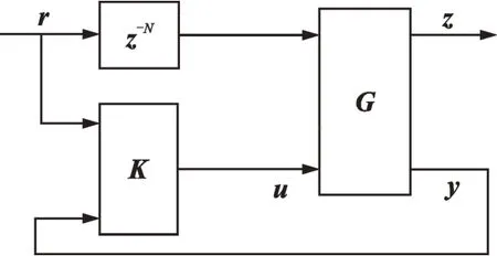
Fig.1 Generalized regulator with preview

2.2 State augmentation
The procedure for converting the H∞preview control problem into standard H∞framework[20]involves augmenting the delay line model to the state space model of the system.This allows us to utilize the methods of H∞control theory[24]for synthesizing controller gains.Let’s define

Let xd(k)be the vector containing the previewed signal available for control

We have

whereφis the system for N-step delay line and Ap,Bp,Cpare defined by

Now,define the augmented state vector

The augmented system formed by combining G andφis given by

where

It is clearly seen that the preview controller of Eq.(1)is a state feedback law for the augmented system P.In general,the state information is available for feedback in flight control applications through the implementation of an observer.The generalized plant with preview can be represented as[24]
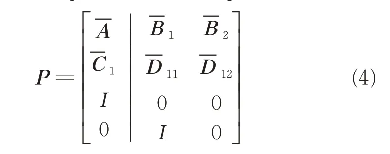
This description of the plant model is now compatible with the full information H∞control problem laid out in Green&Limebeer[24],and which satisfies the following assumptions:(1)is stabiliz -able,2>0,(3)Rankn+m,∀θϵ(-π,π).
Now define
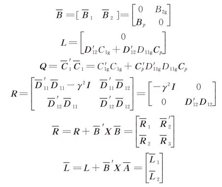
Also define

In Green&Limebeer[24],it is shown that if assumptions(1)—(3)are satisfied,a stabilizing controller K of the form Eq.(1)which achieves<γ,exists,if and only if there exists a semipositive definite matrix X which solves the Discrete algebraic Riccatiequation(DARE)

such that Acis asymptotically stable and

is negative definite.
The controller K is given by

If Eq.(6)is negative definite,X is a feasible solution and if Acis asymptotically stable,X is a stabilizing solution. Hence,the full information H∞control problem has a solution if and only if X is semipositive definite,feasible and stable[24].
By converting the preview problem into a form which is compatible with full information H∞control theory[24],we can utilize the powerful mathematical tools at our disposal to obtain requisite performance and fine tune close loop characteristics of the system like fast convergence,disturbance rejection,uncertainty robustness etc.
3 ACLSFramework
This section describes how to convert a traditional ACLS control problem to a preview control problem so that we may use the methods described in the previous section to obtain a H∞preview controller.
ACLS can be divided into two main subsystems namely the guidance system and the flight control system[25].The guidance system generates landing commands and reference glide slope for the flight control system.The control system can be further divided into lateral control system and longitudinal control system.The preview information available for flight control system is the ideal glide slope height Hcand lateral bias Yc.Fig.2 shows an overview of the ACLS.
3.1 Aircraft model description
The discretized linearized aircraft model has the following form
It was a long walk backs to his Jaguar... a long, slow walk. He never did repair the side door. He kept the dent7() to remind him not to go through life so fast that someone has to throw a brick at you to get your attention.

where the state vector is given as

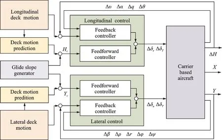
Fig.2 ACLS overview
The individual state variables are the airspeed,angle of attack,pitch rate,pitch,altitude,sideslip angle,roll rate,yaw rate,roll,yaw and lateral bias respectively. The control input vector u=[ΔδeΔδTΔδaΔδr]′consists of control surfaces actuators and throttle inputs respectively as:elevator angle,throttle opening,aileron angle and rudder angle.A and B are state matrix and input matrix respectively.After decoupling the lateral and the longitudinal channel,we have

Here the longitudinal state variable is
and the longitudinal control input is

whereas the lateral state variable is and the lateral control input is


where Alon,Blon,Alat,Blatare the coefficient matrices.
3.2 Longitudinal control system
The longitudinal control system tracks the ideal glide slope altitude by adjusting the elevator angle and the throttle input.The preview information for longitudinal preview controller is the ideal glide slope height Hcrelative to the flight deck.To convert the longitudinal channel into a form like G,we have to augment the preview information Hc(k)to the longitudinal channel given in Eq.(9)and Eq.(10).Define

We obtain the following system

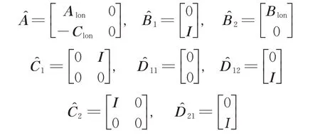
This is now a plant similar to general linearized discrete plant of the form G.Similar to the process explained in Section 2.2,the delay line state can be augmented asχlon(k)=[x^′(k)x′d(k)]′.Define

So,the full information version of longitudinal channel is given as
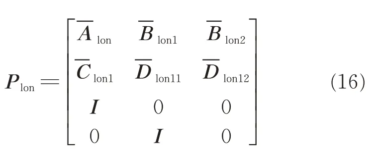
Assuming Plonsatisfies assumptions(1)—(3),the corresponding DARE similar to Eq.(5)can be solved to obtain H∞controller Klonfor a normγ,as shown earlier.The closed loop transfer function(Fig.3)can be obtained by the linear fractional transformation Fl(Plon,Klon).

then

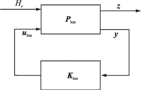
Fig.3 Longitudinal channel closed loop
The minimization of the following cost function

ensures the robustness properties of the H∞controller whereas the added preview improves the tracking and responsiveness of the resulting controller.
For the preview length to be N,the H∞preview controller has the form

3.3 Lateral contr ol system
For a successful landing,the aircraft has to follow a reference glide trajectory.Lateral control system ensures the aircrafts stay on the center line leading to the touchdown point and correct any errors in the azimuthal angle.This is achieved by controlling the roll angle using the aileron and rudder to stay on the trajectory.Reference signal available for preview is the lateral bias Yc.Similar to the longitudinal control system design,we have to augment the preview information Yc(k)to the lateral channel and convert the resulting system to standard H∞framework by further augmenting the delay line as.The H∞lateral preview control input has the following form

4 Simulation Results
For simulation and verification purposes,a linearized model of F/A-18 trimmed at carrier landing phase was used.Trim state values are shown in Table 1.
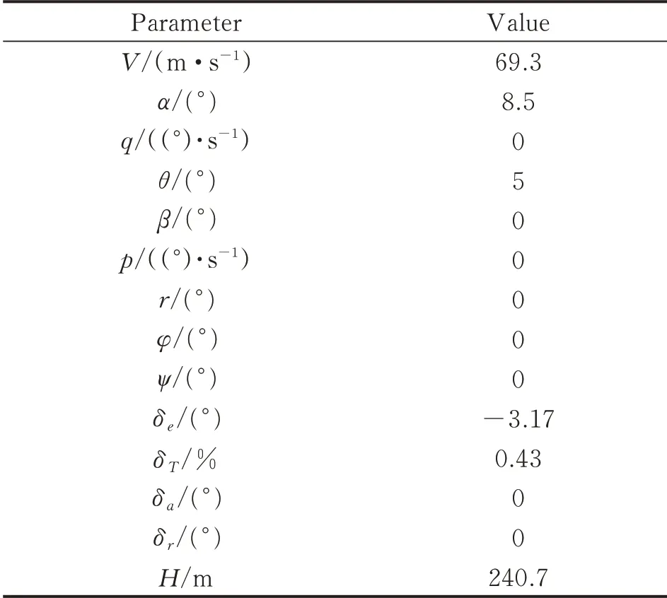
Table 1 Trim state values
The linearized equilibrium state model of the final-approach dynamics has the following form

where state

and input

This state space model can be decoupled into lateral and longitudinal models.
4.1 F/A-18 longitudinal model
After discretization with a sampling time of 0.01 s,the state matrices of longitudinal approach dynamics are given as follows

4.2 F/A-18 lateral model
Similarly,after discretization with a sampling time of 0.01 s,the state matrices of lateral approach dynamics are given as follows

4.3 Controller r esponse
For simulating automatic carrier landing conditions,Fig.4 and Fig.5 show the height response and the velocity response with a longitudinal controller,and Fig.6 shows the deviation response with a lateral controller,both of them are based on H∞preview control which has a preview length of 15.It can be clearly seen that the controller reacts to the future change in input for a better tracking performance.The height response greatly tracks a glide slope as a ramp signal,and the lateral deviation immediately converges to zero in 10 s.All of them clearly depict that the system is acting in advance to be ready for the incoming reference signal.
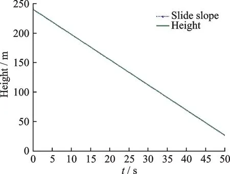
Fig.4 Height response,H∞preview control
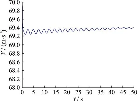
Fig.5 Velocity response,H∞preview control
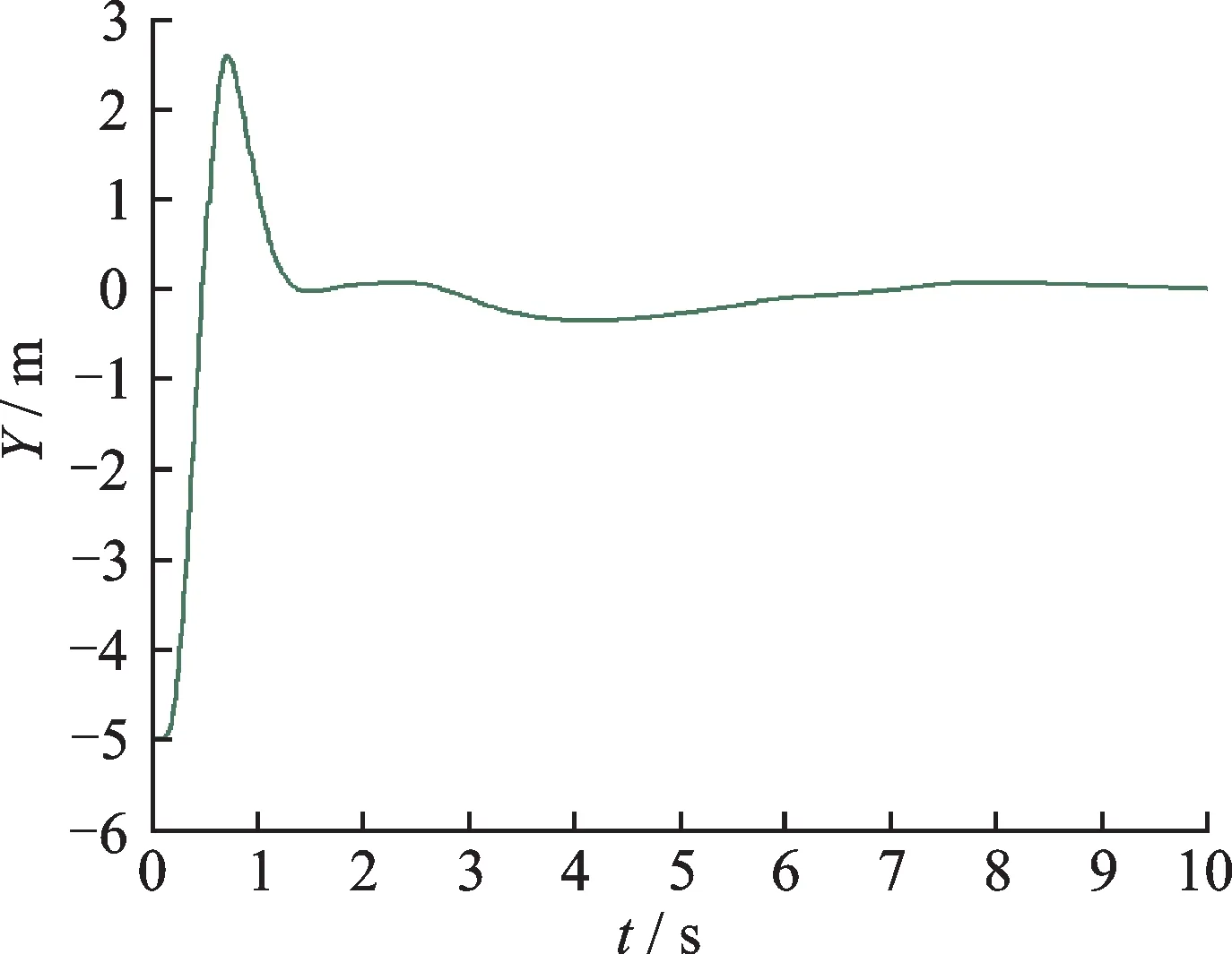
Fig.6 Lateral deviation response,H∞preview control
For comparison,Figs.7—9 show the corresponding responses with controllers based on PID control.It exhibits that the superior control performance of preview control is evident.Owing to the anticipative control effort,preview controller provides a better transient response and quicker tracking with lower tracking error over the transient stage.The maximum tracking error for longitudinal channel with preview is less than that of PID control.
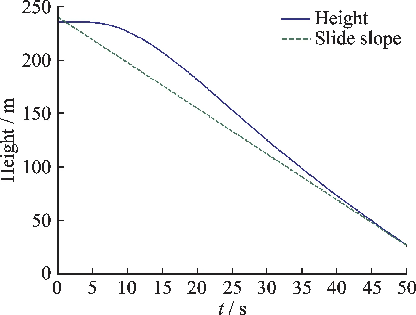
Fig.7 Height response,PID control
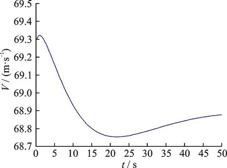
Fig.8 Velocity response,PID control
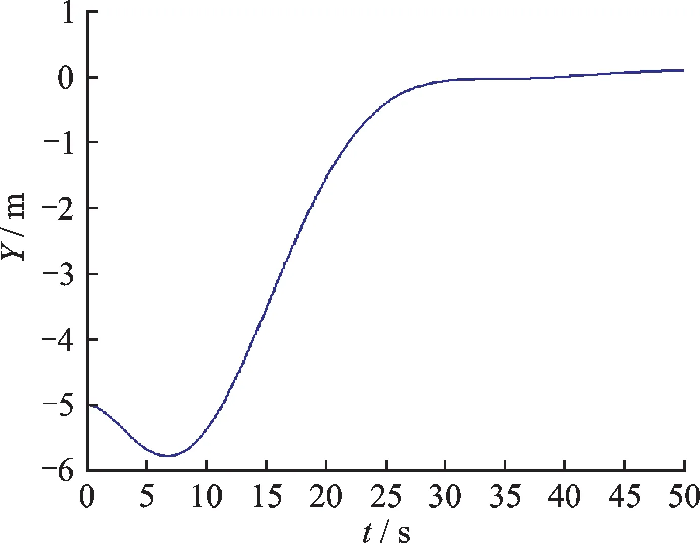
Fig.9 Lateral deviation response,PID control
5 Conclusions
Conventional control methods are causal and cannot make use of future information.Preview control provides us a methodology to develop controllers that can utilize future information of references and disturbances to further improve the controller performance and react a priori.H∞preview control combines the robustness and disturbance rejection properties of H∞feedback control and look ahead properties of feedforward preview control.Most of the work in H∞preview control was scattered over various theoretical results,hence,the practicality from the engineering perspective was low until recently[23].This paper combined the results in order to provide a generic framework and flow for synthesizing preview controllers for ACLS control problem.The process of adding preview to a traditional ACLS plant model and solving the resulting preview control problem using H∞control theory was laid out.Moreover,the procedure was verified using the example of F/A-18 carrier landing problem.Results showed that H∞preview control can provide superior tracking performance compared to conventional PID control.
杂志排行
Transactions of Nanjing University of Aeronautics and Astronautics的其它文章
- BeiDou B1I/B3I Signals Joint Tracking Algorithm Based on Kalman Filter
- Impact Analysis of Solar Irradiance Change on Precision Orbit Determination of Navigation Satellites
- Characterization of Self-driven Cascode-Configuration Synchronous Rectifiers
- Cooperative Search of UAV Swarm Based on Ant Colony Optimization with Artificial Potential Field
- Single-Phase to Three-Phase Inverter with Small DC-Link Capacitor for Motor Drive System
- Analysis of Flight Dynamics Characteristics of Tilt Quad Rotor with Partial Tilt-Wing
